


CHINA J-VALVES Offers Various High-quality I ndustrial Ball Valves
J-VALVES, a distinguished professional ball valve manufacturer rooted in China, takes pride in its extensive product portfolio. Our offerings span a wide range, including trunnion-mounted ball valves, floating ball valves, high-temperature ball valves, high-pressure ball valves, metal-sealed ball valves, ultra-low temperature ball valves, DBB ball valves, Three-way And Four-way Ball Valve, and fully welded ball valves. Each product is a testament to our commitment to precision engineering and reliable performance. Meticulously crafted, they are designed to not only meet but exceed the most stringent industrial demands, ensuring stable operation even under extreme conditions. This enables us to provide our clients with high-value services and makes our valves widely sought-after in industries.
Product Category
Contact Us


-
J-VALVES-Q41F
-
J-VALVES
Overview of the J-VALVES DN50x40 150LB F2 Two Piece Extended Stem Floating Ball Valve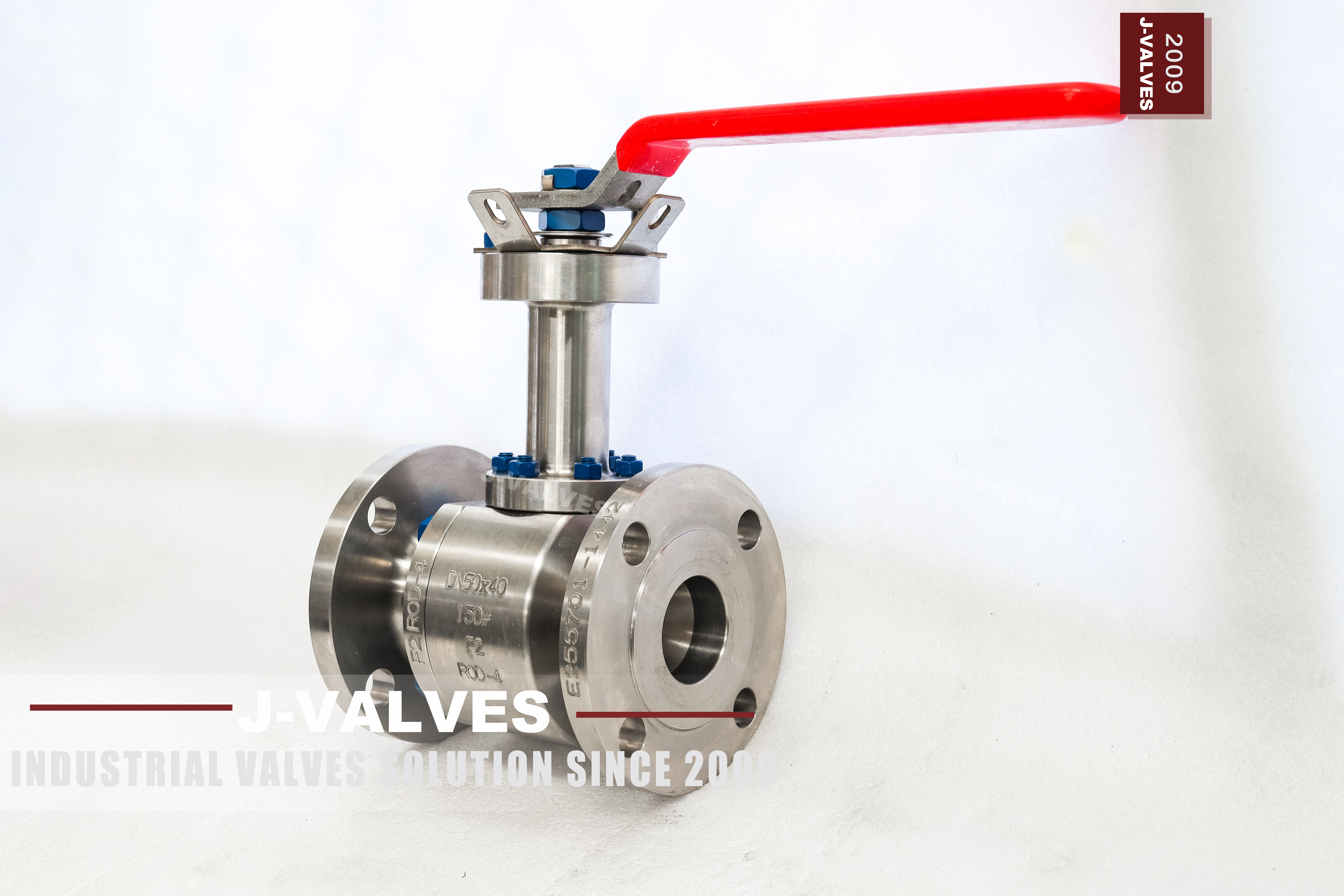
A lever on a normal ball valve is also its position indicator: the handle across the pipe means open, along the pipe means closed, and the quarter turn is short enough that the two are hard to confuse. Put an extension on the stem and that relationship weakens. The lever is now at a working height, the ball is at the bottom of the extension, and the only thing the operator can see is the lever. Everything between the two is hidden inside a tube.
This page is about that hidden length. The valve itself is ordinary: two piece body, floating ball, reduced bore, soft seat, Class 150. What is not ordinary is the checking. A valve that arrives with the lever at ninety degrees has not proved that the ball is at ninety degrees, and on a buried or insulated line the difference is found at the next shutdown, not at commissioning.
Design and Construction
The body splits into two halves at one bolted joint, and the ball floats between two seats rather than sitting on trunnions. Line pressure pushes the ball downstream onto the outlet seat, which is what gives a floating valve its tight shutoff at this size without any spring or wedge. The stem passes through the body into the ball, and the packing that seals the stem sits in the body, not at the top of the extension.
That last point is the one that decides how the valve is maintained. An extension is a tube with a shaft inside it, bolted to the body at the bottom and carrying the operator at the top. It is not a pressure part and it does not move the gland. Whatever leak path the packing has, it is still at the body, which means a packed gland can be tightened from above only if the extension is designed to let a wrench reach it.
Material Options
The body is forged stainless and the nameplate carries a short catalogue code rather than a standard designation. That code is the only string that ties the valve to a mill certificate, so it is what the order and the certificate have to agree on. Reading the code as a standard grade, and writing that grade into the purchase order, invents a requirement the supplier never quoted; the 3.1 documentation is where the actual composition and heat treatment are declared.
Trim is chosen per part. The ball is the same stainless with a hard chrome finish, or a stainless grade where the medium asks for it. The stem is 304 or 316. Seats are PTFE, reinforced PTFE or PPL, and those three do not share a temperature ceiling. Because the extension is also stainless, the whole external column is one alloy family, which matters on a coastal site where a carbon steel column would rust at the joint.
| Component | Standard Material | Optional Upgrade | Service Notes |
|---|---|---|---|
| Body halves | forged stainless, code as stamped | the same alloy | one bolted joint |
| Ball | same stainless with hard chrome | stainless grade | floats on the downstream seat |
| Stem | 304 stainless | 316 stainless | packing stays in the body |
| Seat | PTFE | reinforced PTFE or PPL | sets the service temperature |
| Packing | PTFE | flexible graphite | reached from the body side |
| Extension | stainless tube and shaft | length to the finished grade | not a pressure part |
| Coupling | keyed joint at each end | pinned and marked at assembly | where lost motion appears |
| Ends | raised face to ASME B16.5 | EN 1092-1 drilling | Class 150 only |
| Operator | lever, ninety degree, locking hole | worm gear or actuator | no pad stated on the page |
Technical Specifications
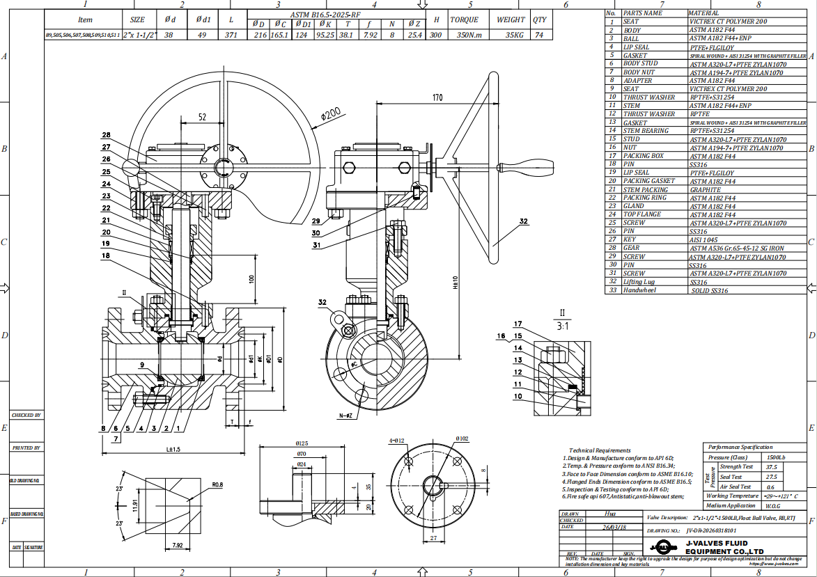
The reduced bore is DN40 inside a DN50 body, so the valve is one size down in the pipe run and the flanges stay at two inch. Face to face follows ASME B16.10 for a Class 150 flanged valve at this size, and the flange is raised face to ASME B16.5, with EN 1092-1 available where the line is drilled to the metric pattern. The extension length is not a catalogue number: it is set by the finished grade, the insulation thickness and the room needed to swing the lever.
Nothing on this page is dimensioned in millimetres, and that is deliberate. The bore and the flange pattern come from the size data sheet, the face to face from the B16.10 table for the size and class, and the assembled height with the extension from the signed general arrangement drawing for the particular build. A buyer who needs the height for a pipe stress model should ask for the drawing rather than scale it off a photograph.
| Item | Value |
|---|---|
| Nominal size | 2 x 1.5 inch (DN50 x DN40) |
| Pressure class | Class 150 (PN 20, the API 6D pressure code) |
| Body style | two piece, one bolted joint |
| Ball support | floating, no trunnion |
| Bore | reduced bore, DN40 through the ball |
| Body material | forged stainless, catalogue code F2 as stamped |
| Ball material | same stainless with hard chrome, stainless grade optional |
| Stem | 304 or 316 stainless |
| Seat | PTFE, reinforced PTFE or PPL |
| Packing | PTFE or flexible graphite |
| Extension | stainless tube and shaft, length set by the finished grade |
| Extension support | mid height support to be specified with the length |
| Position marking | closed position marked on the top plate and the coupling |
| End connection | raised face flange, ASME B16.5 Class 150, EN 1092-1 optional |
| Face to face | dimension on the signed GA drawing, held to ASME B16.10 |
| Design standard | ASME B16.34 and API 608 |
| Test standard | API 598 shell and seat test |
| Test pressure | shell 1.5 times and seat 1.1 times the class rating |
| Temperature range | minus 29 to plus 425 Celsius, metal temperature |
| Temperature limit | set by the seat compound, not by the body |
| Operation | lever with locking hole; gear or actuator on request |
| Actuator pad | not described on this page, to be specified if needed |
| Fire test | not claimed on this page, API 607 to be specified if required |
| Anti static device | not described on this page |
| Marking | size, class, body code, heat number |
| Documentation | EN 10204 3.1 on request |
| Weight | quoted with the drawing for the size and trim ordered |
Standards and Compliance
ASME B16.34 sets the minimum wall and publishes the rating for the material group at Class 150. API 608 is the quarter turn product standard and covers the requirements that are specific to a ball valve: the stem retention, the seat, the marking and the test. API 598 is the test document, and the shell and seat acceptance numbers used here come from it, not from a factory habit.
Two things are not claimed on this page, and both are commonly assumed. There is no fire test certificate described, and no anti static device is listed. On a fuel or solvent line those are usually required, and they are type tests on the design rather than checks performed on each unit, so they have to be named on the order with the standard: API 607 for a soft seated quarter turn valve, API 6FA for a pipeline valve.
| Requirement | Standard | What J-VALVES Supplies |
|---|---|---|
| Pressure boundary | ASME B16.34 | minimum wall and rating for the alloy group at Class 150 |
| Ball valve design | API 608 | stem retention, seat, marking, test |
| Shell and seat test | API 598 | 1.5 times the rating for the shell, 1.1 times for the seat |
| Flange pattern | ASME B16.5 Class 150 | raised face, or EN 1092-1 on request |
| Face to face | ASME B16.10 | flanged valve length for the size and class |
| Marking | API 608 and the order | size, class, body code, heat number |
| Fire test | not claimed on this page | API 607 named on the order if required |
| Documentation | EN 10204 3.1 | issued against the heat number on request |
Manufacturing Process
The body halves are machined so that the bore, the seat pockets and the flange faces stay concentric, and the stem bore is cut square to the ball axis. On a floating valve that squareness is what keeps the seat contact even when the ball is pushed downstream under pressure; a stem bore that is a fraction off square loads one side of the seat harder and shows up as a weeping seat at low pressure.
The extension is assembled as a separate column: shaft, tube, and the coupling that joins the shaft to the stem. That coupling is where lost motion appears. Two keyed or splined joints, one at each end of the extension, each with its own clearance, add up to a few degrees at the lever before the ball moves at all. The column is aligned and pinned at assembly, and the position is marked on the top plate so that it can be checked after installation.

Quality Control and Testing
The shell test is one and a half times the Class 150 rating and the seat test is one and one tenth times, both from API 598, and the seat test is run in both directions because a floating ball seals on the downstream seat only. Cycle the valve a few times before the seat test: a seat that has never been wetted can pass a dry test and weep on the first real operation, which is the kind of result that gets blamed on the installer.
For an extended stem valve there is one extra check that has nothing to do with pressure. With the valve closed, the lever is set at its stop, and the position is marked on the top plate and on the shaft coupling. At site the same two marks are lined up before the lever is fitted, and the ball is checked by feel or by a bore light where the line allows. Without those marks, a valve that is ten degrees off closed looks exactly like one that is closed.
| Step | What Is Checked | Standard or Acceptance |
|---|---|---|
| Incoming forgings | code, heat number, wall thickness | certificate against the stamped code |
| Body machining | seat pocket depth, stem bore squareness | in process gauging against the drawing |
| Ball and seat | roundness, plating, contact pattern | blue check before assembly |
| Extension assembly | coupling fit, column straightness | dial check over the full length |
| Shell test | no leakage through the body wall | API 598 at 1.5 times the rating |
| Seat test | no visible leakage, both directions | API 598 at 1.1 times the rating, after cycling |
| Position marking | closed position marked on plate and coupling | checked against the bore before boxing |

Applications and Industry Service
The extension exists for two duties. One is insulation: a line with a thick cold or hot layer leaves the operator outside the cladding, where a plain lever would be buried in the foam. The other is burial or a valve pit, where the body is below grade and the operator has to be at the surface. In both cases the valve is a small isolation point on a branch, not a control valve, and the duty is either left open or cycled occasionally.
It is the wrong choice in three places. A line that is throttled needs a different valve, because a floating ball seat is not a control element and half open flow will erode the seat face. A line whose medium attacks the seat compound needs a metal seat, which is a different build. And a location where the extension cannot be supported at mid height will put bending into the column every time somebody leans on the lever.

Installation, Operation and Maintenance
Install with the extension vertical, and support the column at mid height where the length calls for it; an unsupported tube with a lever on top is a lever with a long arm, and the bending goes into the coupling. Leave the top plate accessible, because the position marks and the coupling screws are checked from there. On a buried line, the extension is set to the finished grade, not to the trench depth, and that dimension belongs on the order. The extension alignment is set at the top plate, and the valve is left hand operated for the site test.
Operation is a quarter turn, and the lever should move without a cheater. If it needs one, the seat has swollen or the cavity has scaled, and forcing it twists the shaft inside the coupling before it frees anything. Maintenance is split: packing can be reached from the body side, and the seat and ball need the body joint opened. After any work on the coupling, re-mark the closed position before the line is put back in service.
How to Specify and Order
The order needs eight lines, and the extension length is the one most often left vague. Size and class, reduced bore, body code as it will be stamped, seat compound, end facing and drilling standard, extension length measured from the flange face to the top plate, lever or gear, and the test standard. Leaving the drilling standard open is how a valve arrives with the wrong bolt circle for a line that was built to the metric pattern.
Ask for three documents with the quotation: the drawing with the extension length and the position marks, the mill certificate behind the 3.1 documentation, and the test sheet. The drawing is the one that gets used again in ten years when the valve is dug up, so it should show the coupling and the marks, not just the outline. A valve with a wrong drawing is a valve nobody can maintain.
FAQ
Q: Why does the handle not show whether this valve is really closed?
A: Because the handle is at the top of an extension and the ball is at the bottom. Between them sit a shaft, at least one coupling and the stem itself, and each joint has clearance. A few degrees of lost motion at the coupling is invisible at the lever but is enough to leave a soft seat cracked open. The reliable check is the mark on the top plate lined up with the mark on the coupling, plus the bore where the line allows it.
Q: Is the packing still in the body on an extended stem valve?
A: Yes. The extension is a tube with a shaft inside, bolted to the body, and it is not a pressure part. The gland and the packing stay where they were, at the body, which is why a leak shows at the body and not at the top of the column. An extended bonnet is a different construction: there the pressure boundary itself is extended, and the packing sits at the far end.
Q: How long should the extension be?
A: It is not a catalogue dimension. The length is measured from the flange face to the top plate and is set by the finished grade, the insulation thickness and the clearance needed for the lever. It should be written on the order and shown on the drawing, because a valve that arrives short cannot be adjusted at site, and one that arrives long puts the lever where nobody can reach it.
Q: What is the difference between this and the A105 version?
A: The size, the class, the bore and the extension are the same; the body alloy is not. This one is forged stainless under a catalogue code, the other is forged carbon steel. Stainless is bought for the medium, carbon steel for the price, and the seat, the packing and the end facing are ordered the same way on both. The choice between them is a corrosion decision, not a pressure one.
Q: Can this valve be used for throttling?
A: No. It is a quarter turn isolation valve with a soft seat, and a seat that is held partly open in the flow path erodes at the edge and then will not seal at all. If the duty needs modulation, the valve should be a control valve or a different design; if the duty needs occasional partial flow, accept that the seat will be replaced earlier than the rest of the valve.
Q: Is this the same valve as the A105 listing at the same size?
A: It is the same size, class and body pattern with a different body alloy, and the site carries several URLs for both, including one written as PN20 and one written as 2-Piece. Pages that describe one valve under several names compete with each other, so one URL should be kept as the indexed page and the others redirected to it.


Hot Products


News
Ball Valves in A Kraft Pulp Mill: Black Liquor, Green Liquor And The Cost of Choosing The Alloy by Habit
White liquor at pH 14 cracks carbon steel welds, black liquor sets solid below 100 C, green liquor dregs grind seats: alloy choice and torque in a kraft mill.
Read More
Slug Flow And Ball Valves: What Actually Arrives At The Seat
A slug is liquid mass with momentum, not a pressure spike. What changes at the seat, in the cavity and at the actuator when liquid reaches a ball valve.
Read More
Ball Valves in Direct Lithium Extraction: PH 1 Eluate, Gypsum Scale And 438,000 Cycles in Twenty-Five Years
Direct lithium extraction swings valves from pH 1 eluate to pH 12 caustic, 48 column switches a day and gypsum scale. Materials, seats and torque.
Read More
Ball Valves in Geothermal Brine: Silica Scale, Chloride Cracking And The Cooling Trap
Why geothermal brine destroys ball valves: retrograde silica scale, calcite at the flash point, chloride cracking above 60 C and the 250 C seat limit.
Read More