


CHINA J-VALVES Offers Various High-quality I ndustrial Ball Valves
J-VALVES, a distinguished professional ball valve manufacturer rooted in China, takes pride in its extensive product portfolio. Our offerings span a wide range, including trunnion-mounted ball valves, floating ball valves, high-temperature ball valves, high-pressure ball valves, metal-sealed ball valves, ultra-low temperature ball valves, DBB ball valves, Three-way And Four-way Ball Valve, and fully welded ball valves. Each product is a testament to our commitment to precision engineering and reliable performance. Meticulously crafted, they are designed to not only meet but exceed the most stringent industrial demands, ensuring stable operation even under extreme conditions. This enables us to provide our clients with high-value services and makes our valves widely sought-after in industries.
Product Category
Contact Us


-
J-VALVES-Q41F
-
J-VALVES
Overview of the J-VALVES DN25 PN100 F304 Three Piece High Pressure Floating Ball Valve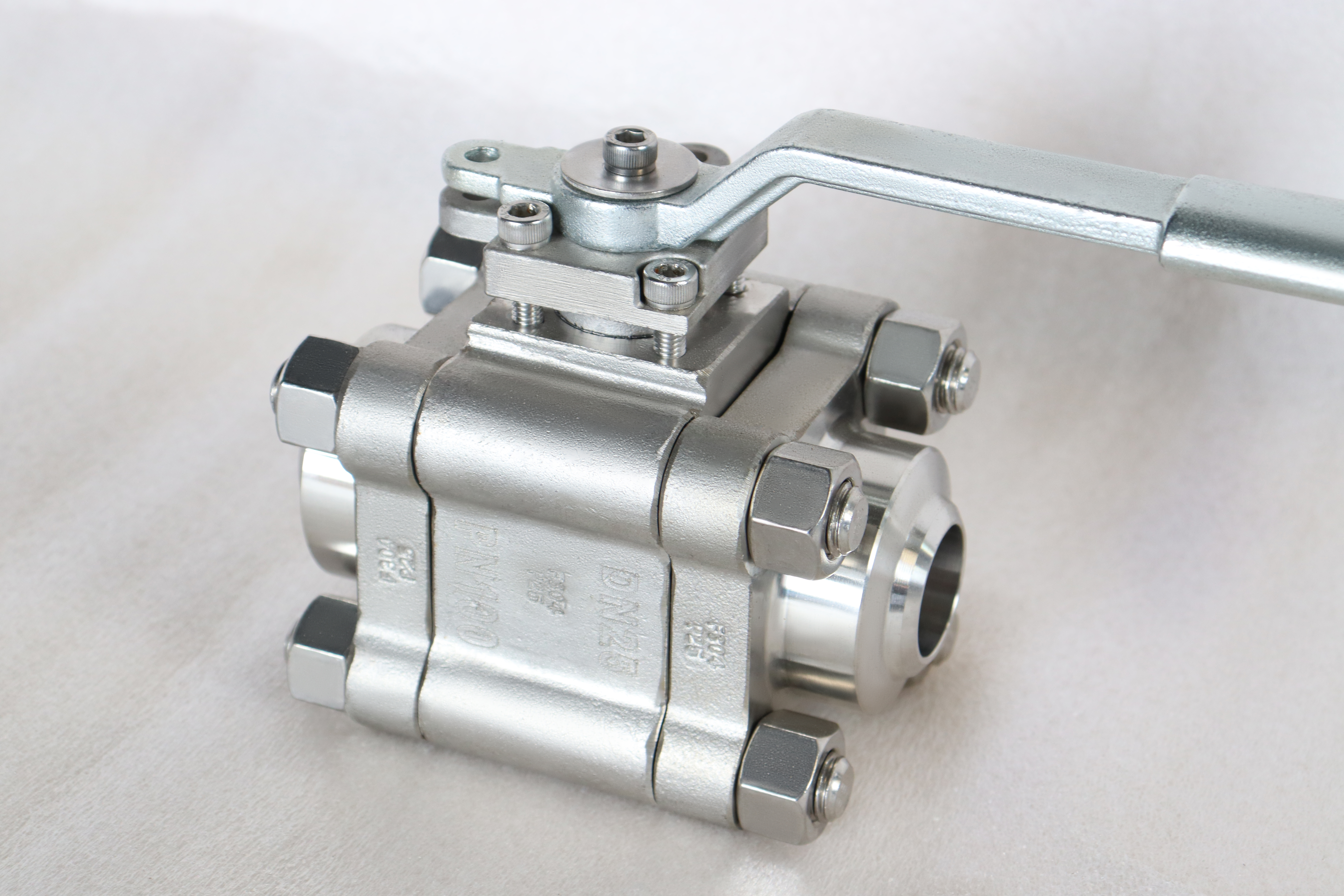
A one inch DN25 three piece floating ball valve at PN100, forged F304 body, flanged to EN 1092-1 or ASME B16.5. In this size the service life is set by cycling, not by pressure: the seat rings and the stem packing wear out long before the body does. The three piece body exists so those two parts can be replaced without cutting the line, and the two bolted joints are the only assembly step that decides whether it leaks.
That framing changes what a buyer should ask about. A valve this size at this class has a wall far thicker than the pressure needs, so shell strength is not where the argument is. The questions that matter are how many times the valve will be operated, how often it is left closed against full differential pressure, and whether the seat and the packing can be renewed where the valve is installed. Those three answers decide the seat compound, the packing style and whether a three piece body is worth its two extra joints.
Design and Construction
Three pieces: a centre body that carries the ball, both seat rings and the stem, and two side bodies that carry the flanges. The ball floats between the two seats, so line pressure pushes it onto the downstream ring and the sealing force rises with the pressure. Each side body is held by a ring of bolts through a gasket, and those two joints are the whole maintenance interface of the product: open one and the seat and the ball on that side are in front of you, with the other seat and both line flanges still in place.
The stem passes through the centre body with a shoulder that stops it being blown out, and the packing sits in an adjustable gland above it. On a valve that is cycled often, the gland is a wear point rather than a formality: every quarter turn works the stem against the packing, and a gland set too tight will wear the stem while one set too loose will weep after the first thermal cycle. The lever has a locking hole so that the valve can be fixed in the position the procedure requires.

Material Options
The body is forged F304, which covers most chemical, water and process duties at this class. F316 is the upgrade where the medium carries chlorides, and it is worth being clear that at PN100 the molybdenum is being bought for corrosion and not for strength. The ball is F304 with hard chrome plating as standard, with F304L as the softer option, and the plating is not cosmetic: it keeps two austenitic stainless surfaces from coming into contact with each other under load, which is where galling starts.
The seat compound is the real choice on this valve. PTFE covers the ordinary range and gives the tightest shutoff, RPTFE and PPL extend the temperature, PEEK takes more cycles at higher pressure, and a metal seat is used where the temperature or the medium rules out polymers. Because the body has far more strength than PN100 requires, the seat is almost always the limiting item, and the packing follows the same logic: PTFE for the lower range and flexible graphite where temperature or fire safety decides it.
| Component | Standard Material | Optional Upgrade | Service Notes |
|---|---|---|---|
| Body and side bodies | F304 forged stainless, solution annealed | F316 for chloride service | three pieces, two bolted joints |
| Ball | F304 with hard chrome plating | F304L, F316 | plating keeps stainless off stainless |
| Seat | PTFE | RPTFE, PPL, PEEK, metal seat | the first wear item on this valve |
| Stem | 304 stainless | 316 stainless | blowout proof shoulder, anti static |
| Packing | PTFE | flexible graphite, braided | the second wear item, adjustable in service |
| Body gasket | PTFE | spiral wound stainless | renewed at every opening |
| End connection | RF flanged to EN 1092-1 PN100 | ASME B16.5 Class 600 | same rating, different drilling |
| Face to face | EN 558 for the PN build | ASME B16.10 for the ASME build | follows the flange system |
| Operator | Lever with a locking hole | worm gear, pneumatic, electric | quarter turn, stops set |
Technical Specifications
The envelope is DN25, PN100, a three piece forged F304 body, full bore, flanged to EN 1092-1 at PN100 or to ASME B16.5 at Class 600, face to face to the table that matches the flange system ordered, a PTFE seat with RPTFE, PPL, PEEK and metal as options, an adjustable gland, a lever with a locking hole, and an API 598 pressure test. PN100 corresponds to Class 600 in the pressure designation table, and the two flange systems do not share a bolt circle even though they carry the same rating.
That last point belongs in the specification and not in a footnote. A PN100 flange to EN 1092-1 and a Class 600 flange to ASME B16.5 are rated the same and drilled differently, so a line list that names the rating without naming the flange standard has not specified the valve. On a one inch line the flange is small enough that the mistake looks minor until the valve arrives, and then the only fix is an adaptor that adds two joints nobody has rated.
| Item | Value |
|---|---|
| Nominal bore | DN25 (1 inch) |
| Pressure class | PN100 (Class 600 equivalent) |
| Body construction | three piece, forged, two bolted joints |
| Body style | 3PC, three piece bolted body |
| Body | F304 forged stainless, solution annealed |
| Body options | F316, F304L |
| Ball | F304 with hard chrome plating |
| Ball options | F304L, F316 |
| Seat | PTFE |
| Seat options | RPTFE, PPL, PEEK, metal seat |
| Stem | 304 stainless |
| Stem option | 316 stainless |
| Packing | PTFE, adjustable gland |
| Packing option | flexible graphite, braided |
| Body gasket | PTFE, renewed at every opening |
| End connection | RF flanged to EN 1092-1 PN100 |
| End option | ASME B16.5 Class 600, different bolt circle |
| Face to face | EN 558 for the PN build, ASME B16.10 for the ASME build |
| Bore | full bore, DN25 |
| Operator | lever with a locking hole |
| Operator options | worm gear, pneumatic, electric |
| Design standard | ASME B16.34 and API 608 |
| Pressure test | API 598, shell 1.5 times, seat 1.1 times |
| Seat test direction | both, because only the downstream ring seals |
| Fire test | API 607 where ordered |
| Material certificate | EN 10204 3.1 per heat |
| Seat replacement | inline replacement by opening one side body |
| Wear items | seat rings and stem packing, both replaceable in the three piece body |
| Marking | size, class, body grade, heat number, flange standard |
| Temperature band | set by the seat compound first, then by the packing |
| Pig passage | full bore, but not a practical pig size |
| Cavity relief | relieves through the seat when the ball is closed |
| Weight | quoted with the drawing for the build ordered |
Standards and Compliance
ASME B16.34 sets the wall and the pressure and temperature rating for the forged austenitic body. API 608 sets the ball valve requirements, including stem retention, marking and testing, and it is the standard this product is normally ordered against. The flange and the face to face follow whichever system the line uses: ASME B16.5 and B16.10 on one side, EN 1092-1 and EN 558 on the other. API 598 is the pressure test in both cases.
Material certification is EN 10204 3.1 per heat, and on an austenitic valve it does more work than on a carbon steel one, because F304, F304L and F316 are visually identical once machined. A certificate that names the grade is only useful if the piece it is attached to has been identified, which is why positive material identification is written into the inspection plan rather than left to the mill certificate. Where a fire test is required it is API 607 for a soft seated valve of this kind.
| Requirement | Standard | What J-VALVES Supplies |
|---|---|---|
| Pressure boundary | ASME B16.34 | wall and rating, austenitic group |
| Ball valve requirements | API 608 | stem retention, marking, testing |
| Flanges, PN build | EN 1092-1 | DN25 PN100 raised face |
| Flanges, ASME build | ASME B16.5 | Class 600 raised face or ring joint |
| Face to face | EN 558 or ASME B16.10 | whichever matches the flange system |
| Pressure testing | API 598 | shell at 1.5 times, seat at 1.1 times |
| Fire test where required | API 607 | on the soft seated build |
| Material certificate | EN 10204 3.1 | per heat, with the grade stated |
Manufacturing Process
The body starts as a forging, is solution annealed, and is machined with the bore, the seat pockets and both flange faces taken from common datums, so that the seat sits square to the bore. The ball is machined, plated and polished, and the seat rings are machined to the interference that the design calls for. On a floating valve that interference is what decides both the shutoff and the operating torque, so the pair is checked together rather than to separate tolerances.
Assembly is where a three piece body differs from a one piece casting. The two side bodies are closed on new gaskets and the bolts are brought up in a cross pattern in stages, so that the gasket is compressed evenly and the joint faces stay parallel. The valve is then shell and seat tested, and the lever is fitted afterwards. Doing it in that order means a leak found during the test belongs to a joint or a seat and never to the operator, which keeps the diagnosis honest.

Quality Control and Testing
Every valve is shell tested at one and a half times its rating and seat tested at one point one times to API 598, and the seat test is run in both directions. On a floating valve that is not a formality, because only the downstream ring seals and the upstream ring is proven only when the flow is reversed. A valve tested from one side has demonstrated one seat and nothing about the other, which is the failure that appears after installation when the line is back pressured from the far end.
The checks specific to this product are dimensional and material. The plating thickness on the ball is measured, the seat interference is checked with the ball in the pocket, and the body joints are checked for gasket seating and bolt extension. Positive material identification confirms the body, the ball and the stem against the certificate, the flange drilling is checked against the ordered standard, and the operating torque is recorded at the end of the test so that the figure on the tag matches what the valve actually does.
| Step | What Is Checked | Standard or Acceptance |
|---|---|---|
| Forging | composition, mechanical properties, solution annealing | 3.1 certificate against F304 |
| Machining | bore and seat pocket square to each other | drawing tolerance |
| Ball plating | thickness and adhesion | specified minimum, measured per batch |
| Seat interference | fit with the ball in the pocket | design fit, checked as a pair |
| Body joints | gasket seating, bolt extension, cross pattern torque | controlled tightening record |
| Shell test | body and both joints at 1.5 times | API 598, no leak |
| Seat test | each seat in both directions at 1.1 times | API 598 |
| Material identification | body, ball and stem against the certificate | positive identification |
| Operating torque | breakaway and running torque at the end of test | recorded on the tag |

Applications and Industry Service
The duty is small bore isolation that gets operated often: chemical injection and dosing skids, sampling and analyzer systems, gauge and instrument isolation, hydraulic and pneumatic supply, pilot plant and test rig pipework, and the block valves on a small pressure reducing station. In most of those the valve is not the process control element; it is the device that lets somebody isolate a small volume safely and start work. That is a duty measured in cycles and in confidence, not in flow coefficient.
It is the wrong valve where the line will be pigged, where the medium attacks F304, and where the seat temperature is above what the ordered compound will hold. It is also the wrong valve where the joint will be broken frequently for cleaning, because every opening needs new gaskets and a controlled retorque, and a body that is opened weekly by habit is a body that will eventually be closed with the wrong preload.

Installation, Operation and Maintenance
Bring the flanges together without pulling them with the studs, fit a gasket suited to the facing, and tighten in a cross pattern in stages. Support the pipe so that the valve is not carrying bending load, because on a small bore line the valve is often the stiffest item between two supports and will take load it was not designed for. Leave the lever locked wherever the procedure requires the valve to stay in one position.
Operate a quarter turn, fully open or fully closed, and do not use the lever to work a stuck ball free: on a valve this size that is the fastest way to damage a seat ring, and a seat damaged that way will not reseal by cycling. The gland can be adjusted with the valve in service. Replacing a seat means isolating, draining and venting, then opening one side body; the gaskets are renewed every time and the joint is retorqued in the same cross pattern as at assembly.
How to Specify and Order
The order has to name the flange standard as well as the rating, and it has to name the two wear parts explicitly. A typical line reads: DN25, PN100, three piece forged F304 body, full bore, flanged to EN 1092-1 PN100 with a raised face, face to face to EN 558, PTFE seat, PTFE packing, lever with a locking hole, API 598. If the line is ASME, the flange and face to face lines change to B16.5 and B16.10 and nothing else does.
Two lines are worth adding. State the expected number of operations per year and whether the valve will normally be closed against full differential pressure, because those two answers decide between PTFE, PPL, PEEK and a metal seat, and they are the difference between a valve that lasts and one that is rebuilt every year. State also whether spares are wanted with the order, since seat rings and gaskets are cheap at the works and slow to arrive later.
FAQ
Q: What fails first on a valve this size?
A: The seat ring, then the stem packing. The body at PN100 has far more wall than the pressure needs, so shell strength is not the limiting item. What wears is the seat surface that the ball lands on every time the valve closes, and the packing that the stem works against on every quarter turn. Both are replaceable, which is the reason to buy a three piece body at this size.
Q: Can the seat be replaced without cutting the line?
A: Yes. Isolate, drain and vent the valve, then undo one side body. That side seat and the ball are exposed while the other seat and both line flanges stay in place. The gaskets are renewed and the joint is retorqued in a cross pattern. What cannot be done in line is re-lapping a metal seat, so a damaged metal seat is replaced.
Q: PN100 or Class 600, does it matter which is written?
A: It matters for the flange, not for the rating. PN100 to EN 1092-1 and Class 600 to ASME B16.5 carry the same pressure rating and are drilled differently, so the flange standard decides whether the valve bolts to the line. The written order should name the flange standard and the face to face that goes with it.
Q: Why is the ball plated if the body is stainless?
A: Because two austenitic stainless surfaces in loaded contact can gall, and the ball seats against a ring thousands of times in service. The hard chrome gives a hard, low friction surface that does not bond to the seat. It also gives a surface that can be re-polished or re-plated when the valve is rebuilt.
Q: What torque should the body bolts be set to?
A: The figure comes from the joint calculation for the gasket and bolt size ordered, and it belongs on the assembly drawing rather than in a general table. What can be stated generally is the method: a calibrated wrench, a cross pattern, and at least two stages, so the gasket is compressed evenly and the two joint faces stay parallel.
Q: Is this valve suitable for sour service?
A: Only if it is ordered for it. Sour service brings hardness limits under NACE MR0175 that apply to the body, the ball, the stem and the bolting, and a standard F304 valve is not automatically compliant. The requirement has to be on the order, because the hardness limits change the material condition and cannot be inspected in after the valve is built.


Hot Products


News
Ball Valves in A Kraft Pulp Mill: Black Liquor, Green Liquor And The Cost of Choosing The Alloy by Habit
White liquor at pH 14 cracks carbon steel welds, black liquor sets solid below 100 C, green liquor dregs grind seats: alloy choice and torque in a kraft mill.
Read More
Slug Flow And Ball Valves: What Actually Arrives At The Seat
A slug is liquid mass with momentum, not a pressure spike. What changes at the seat, in the cavity and at the actuator when liquid reaches a ball valve.
Read More
Ball Valves in Direct Lithium Extraction: PH 1 Eluate, Gypsum Scale And 438,000 Cycles in Twenty-Five Years
Direct lithium extraction swings valves from pH 1 eluate to pH 12 caustic, 48 column switches a day and gypsum scale. Materials, seats and torque.
Read More
Ball Valves in Geothermal Brine: Silica Scale, Chloride Cracking And The Cooling Trap
Why geothermal brine destroys ball valves: retrograde silica scale, calcite at the flash point, chloride cracking above 60 C and the 250 C seat limit.
Read More