


CHINA J-VALVES Offers Various High-quality I ndustrial Ball Valves
J-VALVES, a distinguished professional ball valve manufacturer rooted in China, takes pride in its extensive product portfolio. Our offerings span a wide range, including trunnion-mounted ball valves, floating ball valves, high-temperature ball valves, high-pressure ball valves, metal-sealed ball valves, ultra-low temperature ball valves, DBB ball valves, Three-way And Four-way Ball Valve, and fully welded ball valves. Each product is a testament to our commitment to precision engineering and reliable performance. Meticulously crafted, they are designed to not only meet but exceed the most stringent industrial demands, ensuring stable operation even under extreme conditions. This enables us to provide our clients with high-value services and makes our valves widely sought-after in industries.
Product Category
Contact Us


Pressure Class: 150LB to 2500LB (PN20 to PN420)
Temperature Range: -29℃ to +425℃
Body / Bonnet: Forged steel including ASTM A105, A350 LF2, A182 F304/F316/F51, etc.
Ball: Material matching the valve body + hard chrome plating or nitriding treatment
Stem: 17-4PH, 316, F51 and other stainless steels
Seat: PTFE, RPTFE, PPL (reinforced PTFE)
Sealing Materials: PTFE/RPTFE/PPL (seat), flexible graphite or PTFE (stem packing)
Extended Stem: Material matching the valve body or stainless steel, length customized according to service conditions
End Connection: Flanged (RF Raised Face or RTJ Ring-Type Joint, conforming to ASME B16.5 / EN 1092-1)
Operation: Lever (quarter-turn 90° operation, with optional locking hole), worm gear, pneumatic, electric (optional)
Design Standards: ASME B16.34, API 608
Inspection & Test Standard: API 598
Face-to-Face Dimension: Conforms to ASME B16.10
-
J-VALVES-Q41F
-
J-VALVES
Overview of the J-VALVES Two Piece Forged Steel Long Rod Floating Ball Valve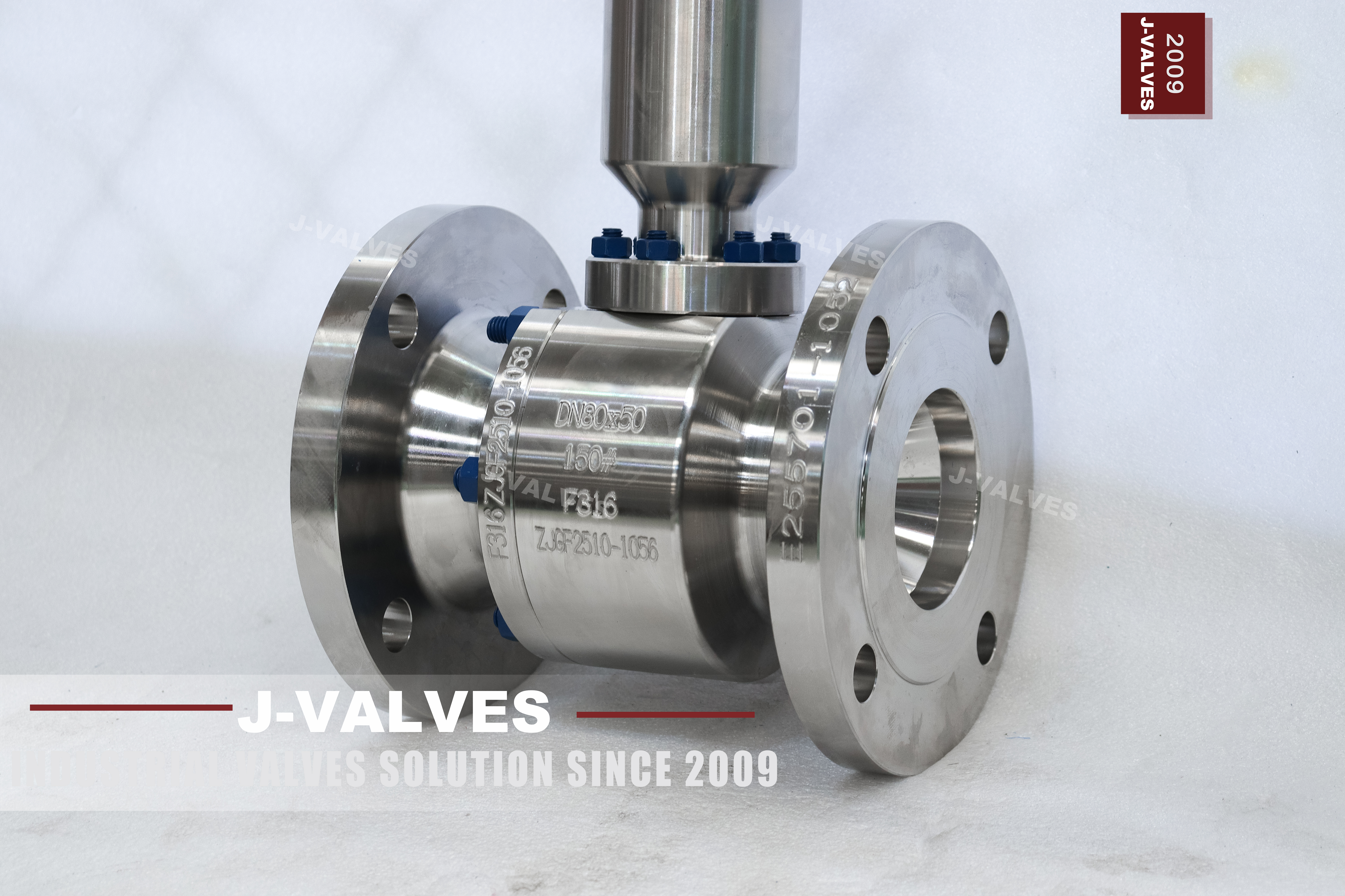
A long rod valve is an ordinary floating ball valve with one part changed: the connection between the ball and the operator is extended, so that the body can sit underground or inside insulation while the handwheel or the actuator stays where a person can reach it. The body is a two piece forging, the ball floats onto the downstream seat, the ends are flanged, and the only unusual item on the drawing is the rod and its coupling.
That one change brings its own set of problems, and they are mechanical rather than hydraulic. A rod that is three metres long twists before the ball moves, has to be guided somewhere between the valve and the handle, and has to be protected from the groundwater it is standing in. Those three things are what this page is about; the length itself is a site dimension and is covered on the extended stem pages.
Design and Construction
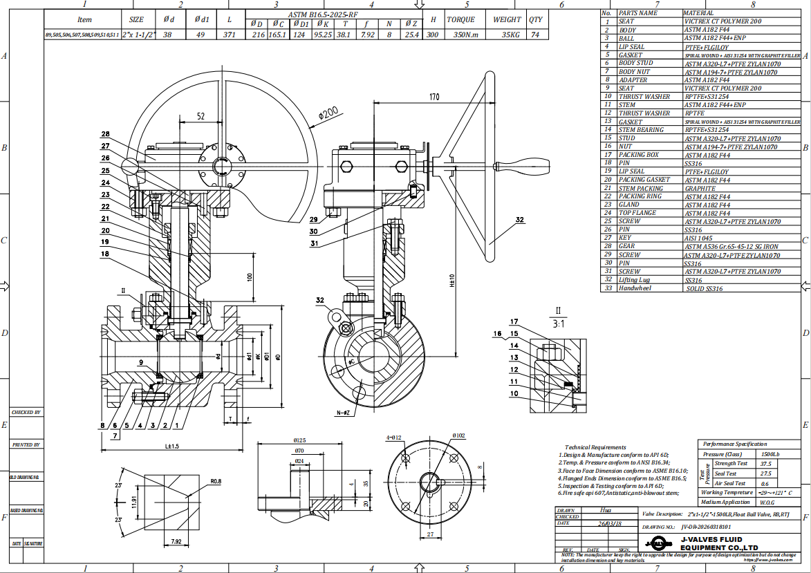
The valve end of the assembly is a two piece body: a main body holding the stem and one seat, an end cap carrying the other seat and one flange, closed on a single bolted joint. The stem passes through the bonnet and is retained against blowout, and the packing sits in the bonnet where it always sits. The rod is bolted to the top of the stem through a coupling, above the packing, so nothing about the pressure boundary moves.
The coupling is the part that deserves attention. It is a keyed or pinned sleeve joining two shafts that must stay concentric under torque, and it is where a long rod valve fails first: a key that is a loose fit will develop backlash, and backlash on a quarter turn valve becomes a ball that stops a few degrees short of the seat. Above about a metre and a half the rod also needs an intermediate guide, because the stem bearing at the valve is not designed to hold a long shaft straight.
Material Options
The body is forged carbon steel, A105 as standard, with A350 LF2 where the site temperature goes below the carbon steel limit and A182 F304, F316 or F51 where the medium is corrosive. The rod follows the body or is made in stainless regardless, because the part of it that stands in a pit or in soil sees water and air rather than the process medium.
The stem is 17-4PH or 316, and it is worth separating the two duties: the stem inside the valve has to be corrosion resistant to the medium, while the rod outside has to be stiff and corrosion resistant to the environment. On a buried installation the rod is often stainless even when the body is carbon steel, which is the opposite of what a buyer assumes when both are quoted as matching the body.
| Component | Standard Material | Optional Upgrade | Service Notes |
|---|---|---|---|
| Body and end cap | ASTM A105 forged carbon steel, normalised | A350 LF2, A182 F304, F316, F51 | two pieces, one bolted joint |
| Ball | Body grade with hard chrome plating | nitrided, 316 stainless | floats onto the downstream seat |
| Stem | 17-4PH precipitation hardening stainless | 316, F51 | blowout proof, keyed for the coupling |
| Rod | Stainless steel, matched to the environment | carbon steel with coating where specified | straightened, guided over its length |
| Coupling | Keyed sleeve with set screws | pinned or clamped | the joint that decides the backlash |
| Seat | PTFE | RPTFE, PPL | backed by body and cap |
| Packing | PTFE | flexible graphite | adjustable gland, in the bonnet at the valve |
| End connection | RF or RTJ flanged to ASME B16.5 | EN 1092-1 where ordered | flange standard stated on the order |
| Operator | Lever with a locking hole | worm gear, pneumatic, electric | fitted at the top of the rod |
Technical Specifications
The envelope is DN15 to DN300, Class 150 to 2500, two piece forged body, full or reduced bore, flanged RF or RTJ to ASME B16.5 or EN 1092-1, PTFE, RPTFE or PPL seat, and a rod whose length, diameter and guide arrangement are shown on the drawing. Face to face is ASME B16.10 for the body size and class, and does not include the rod.
Two fields on this page cannot be filled in from a catalogue. The rod length is measured from a stated datum, which is normally the top face of the body or the centre line of the flange, to the top of the rod, and it has to be quoted with that datum or it means nothing. The rod diameter and the guide spacing come from the torque and the unsupported length, and they are engineering decisions rather than options.
| Item | Value |
|---|---|
| Nominal size | DN15 to DN300 (1/2 to 12 inch) |
| Pressure class | Class 150 to 2500 (PN20 to PN420) |
| Body construction | two piece, one bolted joint |
| Body | ASTM A105 forged carbon steel |
| Body options | A350 LF2, A182 F304, F316, F51 |
| Ball | body grade with hard chrome plating |
| Ball options | nitrided, 316 stainless |
| Stem | 17-4PH, blowout proof |
| Stem options | 316, F51 |
| Rod | stainless steel as standard |
| Rod option | carbon steel with a coating |
| Rod length | set by the drawing, measured from a stated datum |
| Rod diameter | sized on the torque and the unsupported length |
| Guide | intermediate bracket above about a metre and a half |
| Coupling | keyed or pinned sleeve, backlash checked |
| Seat | PTFE |
| Seat options | RPTFE, PPL |
| Packing | PTFE, in the bonnet at the valve |
| Packing option | flexible graphite |
| End connection | RF flanged to ASME B16.5 |
| End options | RTJ, EN 1092-1 |
| Bore | full bore or reduced bore |
| Face to face | ASME B16.10, body only |
| Operator | lever with a locking hole |
| Operator options | worm gear, pneumatic, electric |
| Design standard | ASME B16.34 and API 608 |
| Pressure test | API 598, shell 1.5 times, seat 1.1 times |
| Packing location | in the bonnet at the valve, not moved by the rod |
| Temperature extension | needs an extended bonnet, not a long rod |
| Material certificate | EN 10204 3.1 per heat |
Standards and Compliance
The valve half of the assembly is covered by the usual set: ASME B16.34 for wall and rating, API 608 for the ball valve requirements, ASME B16.5 for the flanges and ASME B16.10 for the face to face. None of those standards mentions a long rod, because it is an accessory rather than part of the valve, and that is why the rod has to be specified on a drawing instead of by reference.
What the standards do cover is the consequence. If the rod transmits torque to a stem that is part of the pressure boundary, the stem and its retention still have to meet the valve standard, and the coupling must not put a bending load on the stem. A rod that is bolted on out of line loads the stem sideways, which is a pressure boundary problem caused by an accessory.
| Requirement | Standard | What J-VALVES Supplies |
|---|---|---|
| Pressure boundary | ASME B16.34 | wall thickness and rating for the body grade |
| Ball valve requirements | API 608 | stem retention, marking, testing |
| Flanges | ASME B16.5 or EN 1092-1 | whichever the line is built to |
| Face to face | ASME B16.10 | body only, the rod is not included |
| Rod and coupling | shown on the drawing | no valve standard covers the extension |
| Pressure testing | API 598 | shell at 1.5 times, seat at 1.1 times |
| Coating on the buried section | declared per order | coverage checked including the ends |
| Material certificate | EN 10204 3.1 | body, stem and rod per heat |
Manufacturing Process
The body is forged, normalised and machined in the usual sequence, and the stem is machined with its blowout shoulder and its key or flat for the coupling. The rod is machined separately, straightened and, where the length demands it, supplied in sections with an intermediate guide bracket that is set to the drawing. Nothing in the body changes for a long rod build except the top of the stem, which is the point: the pressure boundary is a standard part and the extension is an accessory bolted to it.
The assembly is trial fitted before despatch: the coupling is checked for fit and backlash, the rod is checked for straightness over its full length, and the guide positions are marked. For long rods the assembly is then split for shipping, with the coupling and its fasteners packed separately and a setting dimension supplied so that the joint goes back together at the right height rather than at whatever the site finds convenient.

Quality Control and Testing
The valve is shell tested and seat tested before the rod is fitted, so that a leak at the packing is diagnosed with the rod off. After assembly the operator is turned through a full quarter turn and the travel stops are set, and the torque at the handwheel is recorded: on a long rod that figure is not the same as the valve torque because the rod absorbs some of it and adds its own friction.
The checks specific to this product are the ones a valve test does not cover: rod straightness measured over the full length, coupling backlash measured at the handle, guide bracket positions against the drawing, and the coating or wrapping on the buried section checked for coverage including the ends, which is where a coating always fails first. Those are the four checks a valve test does not cover, and they are the four that decide whether the valve is usable from the surface.
| Step | What Is Checked | Standard or Acceptance |
|---|---|---|
| Forging | composition, mechanical properties, normalising record | 3.1 certificate against the grade |
| Stem | blowout shoulder, key or flat for the coupling | drawing dimension |
| Rod straightness | measured over the full length | drawing tolerance |
| Coupling fit | backlash measured at the handle | acceptance figure on the drawing |
| Guide brackets | position and alignment against the drawing | marked before despatch |
| Shell and seat test | before the rod is fitted | API 598, so a packing leak is not misread |
| Travel stops | quarter turn, stops at both ends | set with the rod fitted |
| Handwheel torque | recorded with the rod on | issued for actuator sizing where relevant |
| Coating | coverage on the buried section, including the ends | holiday test where specified |

Applications and Industry Service
The duty is a valve that has to be operated from outside whatever contains it: buried water and gas distribution mains, district heating lines under insulation, tank farm lines in a pit, and process lines where the valve sits inside a jacket or a cold box and the handle has to be outside. It is also used where the valve is simply too low to reach, which is a maintenance decision as much as a design one.
It is the wrong product where the reason for the extension is temperature rather than access, because a long rod does not move the packing away from the heat: the packing is still in the bonnet at the valve. A hot or cryogenic line needs an extended bonnet, where the extension is part of the pressure boundary and the packing moves with it. Getting those two confused is the most expensive mistake on this product.

Installation, Operation and Maintenance
Set the valve so the rod is vertical unless the drawing says otherwise, and fix the guide bracket to a support that is independent of the pipe, so that pipe movement does not push the rod sideways. On a buried line, the rod is run inside a sleeve or a standpipe, and the annulus is sealed at the top to keep groundwater out of the pit; a pit that fills with water will corrode the coupling first.
After installation, check that the handle turns the full quarter without binding, and adjust the packing gland only after the valve has been cycled a few times, because a gland set cold on a long rod will be too tight once the rod has taken up its position. When the valve is excavated for service, the coupling is the first thing to inspect: backlash there will be read at the handle as a valve that no longer closes fully.
How to Specify and Order
On this product most of the argument happens before the valve is even quoted, and it is over the rod. Put the length first, with the datum it is measured from, then the rod material, the diameter and the guide arrangement, and only then the valve fields. A workable line reads: DN100, Class 150, body A105, full bore, RF flanged, RPTFE seat, rod 1800 mm from the body top face to the top of the rod, rod in 316, one intermediate guide, lever with a locking hole.
Two things are worth stating that the form does not ask for. Say what the rod will stand in, because soil, water, insulation and a heated jacket each imply a different protection on the buried or enclosed section; and say whether the valve will be operated while the line is under pressure, because the torque at the handle with the line loaded is what the rod and the coupling are sized for.
FAQ
Q: Does a long rod move the packing away from the heat?
A: No. The packing stays in the bonnet at the valve, and only the stem extension and the operator move. Where the purpose is to get the packing out of a hot or cold zone, the part required is an extended bonnet, where the extension is itself part of the pressure boundary and the packing travels with it. A long rod is an access solution, not a temperature solution.
Q: How long can the rod be?
A: It is a calculation rather than a catalogue value: the length is limited by the torque that has to be transmitted, the stiffness of the rod, and the number of intermediate guides that can be fixed to a support. Short extensions are a single rod; long ones are split with guides between sections. The figure comes from the drawing for the installation, not from a table.
Q: What fails first on a long rod valve?
A: The coupling. A keyed sleeve that is a loose fit develops backlash, and on a quarter turn valve backlash shows up as a ball that stops short of the seat, so the valve leaks while the handle feels like it has reached the stop. Next is the packing, worn oval because the rod is not concentric with the stem.
Q: Should the rod be the same material as the body?
A: Not necessarily, and on a buried installation it usually should not be. The body has to resist the medium, while the rod has to resist soil, water and air, and it also has to be stiff. A stainless rod on a carbon steel body is a normal combination and is often the right one, even though it costs more than matching the body.
Q: How is the buried section protected?
A: With a coating or a wrapping specified for burial, applied over the full length including the ends, and checked for coverage before despatch. The ends are where coating fails first, and they are also where the corrosion starts. Where the rod runs in a standpipe or a sleeve, the annulus is sealed at the top so that the pit does not fill with groundwater.
Q: Can the valve be operated with the line under pressure?
A: Yes, and that is the normal case, but it is the case the rod has to be sized for. The torque at the handle with the line loaded is higher than the bench figure, and the rod, the coupling and the guide spacing all follow from it. Tell the supplier that the valve will be operated live, because a rod sized on the bench torque will feel springy in service.
Hot Products


News
Ball Valves in A Kraft Pulp Mill: Black Liquor, Green Liquor And The Cost of Choosing The Alloy by Habit
White liquor at pH 14 cracks carbon steel welds, black liquor sets solid below 100 C, green liquor dregs grind seats: alloy choice and torque in a kraft mill.
Read More
Slug Flow And Ball Valves: What Actually Arrives At The Seat
A slug is liquid mass with momentum, not a pressure spike. What changes at the seat, in the cavity and at the actuator when liquid reaches a ball valve.
Read More
Ball Valves in Direct Lithium Extraction: PH 1 Eluate, Gypsum Scale And 438,000 Cycles in Twenty-Five Years
Direct lithium extraction swings valves from pH 1 eluate to pH 12 caustic, 48 column switches a day and gypsum scale. Materials, seats and torque.
Read More
Ball Valves in Geothermal Brine: Silica Scale, Chloride Cracking And The Cooling Trap
Why geothermal brine destroys ball valves: retrograde silica scale, calcite at the flash point, chloride cracking above 60 C and the 250 C seat limit.
Read More