


CHINA J-VALVES Offers Various High-quality I ndustrial Ball Valves
J-VALVES, a distinguished professional ball valve manufacturer rooted in China, takes pride in its extensive product portfolio. Our offerings span a wide range, including trunnion-mounted ball valves, floating ball valves, high-temperature ball valves, high-pressure ball valves, metal-sealed ball valves, ultra-low temperature ball valves, DBB ball valves, Three-way And Four-way Ball Valve, and fully welded ball valves. Each product is a testament to our commitment to precision engineering and reliable performance. Meticulously crafted, they are designed to not only meet but exceed the most stringent industrial demands, ensuring stable operation even under extreme conditions. This enables us to provide our clients with high-value services and makes our valves widely sought-after in industries.
Product Category
Contact Us


-
J-VALVES-Q41F
-
J-VALVES
Overview of the J-VALVES DN50x40 150LB F2 Extended Stem Ball Valve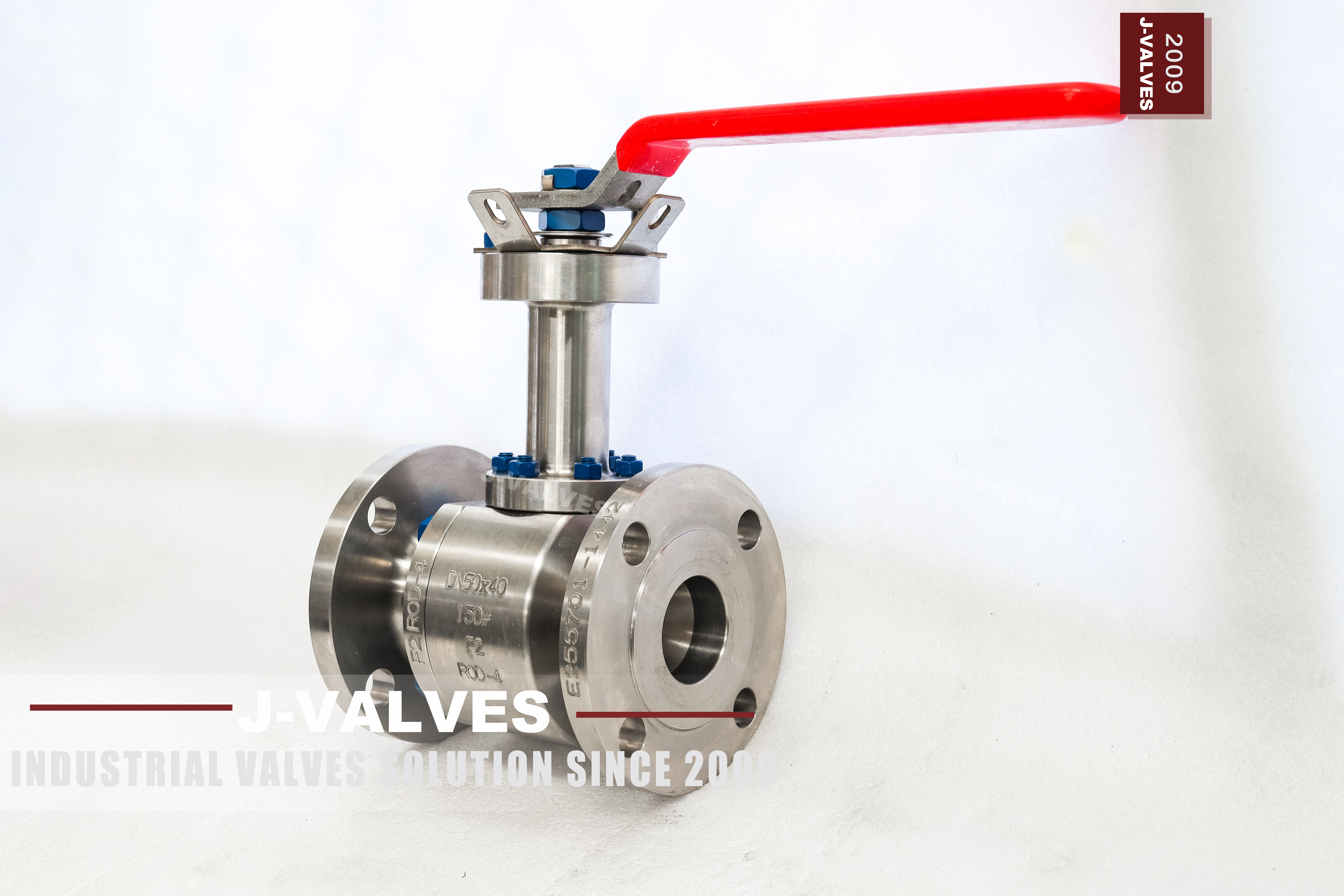
This is a small flanged valve with a long neck: DN50x40, Class 150, a DN40 bore through DN50 flanges, and a stem that runs up through an extension so the lever sits clear of insulation or above a pit. The body is stamped F2, which is the first thing to understand about this page. The valve is supplied with the certificate for the heat that was cast, and the heat number is stamped on the body beside the code, so the two can be matched by anyone holding the valve.
F2 is a catalogue code. It is not an ASTM designation, not an EN designation and not a UNS number, and it cannot be resolved into a grade by looking at it. It exists because a customer, a project or a catalogue needed a short code for a body specification, and the foundry stamps that code on the body so the valve can be identified against the order.
That makes this valve easy to buy and easy to buy wrongly. The code tells you which build it is; it does not tell you what steel it is. The steel is declared on the EN 10204 3.1 certificate, and the page below is written so that the two are never confused, because a valve page that silently translates F2 into a grade is guessing on the customer behalf.
Design and Construction
The ball floats between two seat rings. Line pressure on the upstream half of the ball pushes the whole ball downstream until it presses on the outlet seat, so the seal is produced by the pressure and tightens as the pressure rises. At DN40 bore and Class 150 the seat load is small, the torque is small, and a lever at the top of the extension is all the operator the valve needs.
The body is in two pieces with one bolted joint on the flange side. The end piece comes off, the seat and the ball come out, and the second seat is reached from inside the centre section once the ball is out. One joint means one pressure boundary to maintain and one gasket to stock, which on a small bore valve is most of the maintenance budget.
The extension is a stem and a support tube. The packing gland stays on the body where the stem crosses the pressure boundary, and everything above it is dry: the tube carries the operator and takes the side load a lever puts on it, and the stem inside it is one piece from the ball slot to the handle. Nothing in the extension holds pressure, so the extension does not change the rating.
The lever sits on a square drive at the top with a locking hole so the valve can be padlocked. Under the lever there is a mounting pad, which is what allows the same valve to be supplied with a small pneumatic or electric actuator later without changing the body. On a buried or insulated installation that pad is usually the reason the extension exists at all.
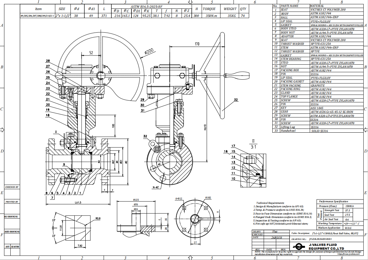
Material Options
The body is F2: forged stainless, as stamped. What that means in practice is that the material is a forged austenitic stainless steel of the maker specification, and the exact grade, its chemistry and its mechanical properties are declared per heat on the EN 10204 3.1 certificate that ships with the valve. The certificate is the document that turns a code into a material, and it is the only document that does.
The trim follows the same rule. The ball is stainless with a lapped sealing face, optionally hard chrome plated; the stem is stainless, with 17-4PH where a longer extension needs more torsional stiffness; the seat is PTFE as standard, RPTFE or PPL where the line runs hotter. Where a project names a grade for the ball or the stem, that grade goes on the order and on the certificate, not into an assumption.
| Component | Standard Material | Optional Upgrade | Service Notes |
|---|---|---|---|
| Body and end piece | F2 forged stainless, catalogue code as stamped | grade named on the order and the 3.1 certificate | one bolted body joint |
| Ball | Stainless, lapped sealing face | hard chrome plating; grade declared on the certificate | floating, one sealing face at a time |
| Stem | Stainless | 17-4PH for long extensions | one piece from the ball slot to the lever |
| Extension tube | Stainless or carbon steel | length per drawing | dry above the gland, carries the operator |
| Seat ring | PTFE or RPTFE | PPL | sets the temperature limit |
| Body gasket | Graphite spiral wound | PTFE envelope | new gasket at every joint opening |
| Stem packing | PTFE V-ring | Flexible graphite | compressed at the body gland |
| Body bolts | Stainless steel | grade stated on the 3.1 certificate | one joint, cross pattern |
| Operator | Lever at the top of the extension | Worm gear, pneumatic, electric | mounting pad at the top |
Technical Specifications
Almost nothing here can be read off a catalogue table. DN50x40 reduced bore, Class 150, raised face flanges, body marked F2, and an extension whose length is a dimension on the drawing, taken from a stated datum to the top face and approved before the stem is cut. Face to face follows ASME B16.10 because the ends are flanged, and testing follows API 598. The drawing and the EN 10204 3.1 certificate travel as a pair, because the marking is a code and the certificate is the only document that says what the code was made from.
Two things have to be settled before the valve is built, and one of them is unusual. The usual one is the extension length and its datum. The unusual one is the material question: if the project requires a named grade rather than the F2 code, that has to be stated at the enquiry, because the certificate is written against the heat that was cast, not against a preference expressed after delivery.
| Item | Value |
|---|---|
| Nominal size | DN50 x DN40 (2 x 1.5 inch), reduced bore |
| Pressure class | Class 150 (PN20) |
| Body construction | two piece, one bolted joint |
| Ball support | floating, no trunnion |
| Body material | F2 forged stainless, catalogue code as stamped |
| Grade declaration | EN 10204 3.1 certificate, grade stated per heat |
| Material group | follows the grade declared on the certificate |
| Rating at 38 C | Class 150 = 19.6 bar |
| Temperature range | set by the seat compound and the grade on the certificate |
| Ball | stainless, lapped sealing face |
| Ball option | hard chrome plating |
| Stem | stainless |
| Stem option | 17-4PH |
| Seat | PTFE or RPTFE |
| Seat option | PPL |
| Packing | PTFE V-ring |
| Packing option | flexible graphite |
| Body gasket | graphite spiral wound |
| Body bolts | stainless steel, grade on the certificate |
| Bore | DN40 through DN50 ends |
| End connection | raised face flange, ASME B16.5 or EN 1092-1 as ordered |
| Face to face | ASME B16.10 |
| Stem extension | length per drawing, with a stated datum |
| Wall thickness | ASME B16.34 |
| Design standards | ASME B16.34 and API 608 |
| Pressure testing | API 598 shell and seat, both directions |
| Operator | lever at the top of the extension |
| Actuation options | worm gear, pneumatic, electric |
| Marking | size pair, class, F2 code and heat number on the body |
| Documentation | EN 10204 3.1, test record, drawing with the extension dimension |
Standards and Compliance
The valve is built as a steel ball valve, so ASME B16.34 governs the wall thickness and the rating and API 608 governs the ball valve details: the anti static path, the blowout proof stem and the nameplate. Which material group of B16.34 applies, and therefore which rating column, depends on the grade declared on the certificate, which is another reason the certificate is not optional paperwork.
The flanges are to ASME B16.5 or EN 1092-1 as ordered, and at DN50 the two do not share a bolt circle even though both are called 150 or PN20. Face to face follows ASME B16.10 for the flanged pattern. Pressure testing is to API 598, and the material certificate is to EN 10204 3.1 with the grade and the heat number stated on it.
| Requirement | Standard | What J-VALVES Supplies |
|---|---|---|
| Wall thickness and rating | ASME B16.34 | material group follows the grade on the certificate |
| Ball valve specifics | API 608 | anti static path, blowout proof stem, nameplate |
| Flanges | ASME B16.5 or EN 1092-1 | stated on the order; the bolt circles differ |
| Face to face | ASME B16.10 | flanged pattern for DN50 Class 150 |
| Pressure testing | API 598 | shell at 1.5 times, seat at 1.1 times, both directions |
| Material certificate | EN 10204 3.1 | grade, heat number, composition and mechanical properties |
Manufacturing Process
The body is forged, solution annealed and machined, with the seat pocket and the flange facing cut in one setting so the seat ring sits square to the ball axis. The heat number is stamped on the body next to the F2 code, and that pair of markings is what ties the finished valve to the certificate. Without the heat number the code is just a label.
The stem is turned, heat treated and straightened, then checked for runout over its full length, because a long stem that is straight over a short length will still bind in the gland at the body. Assembly is seats and ball into the body, the joint closed on a new gasket, the stem through the extension, the packing compressed at the body gland, and the lever or pad fitted at the top.

Quality Control and Testing
Every heat is identified before it is machined. The composition is checked, the mechanical properties are tested, and where the customer asks for it the finished parts are checked by positive material identification so that the alloy in the valve matches the alloy on the certificate. That check is the practical answer to a code like F2: it does not decode the code, it proves the material.
The records for this valve are short but specific. Flange faces are checked for flatness and the bolt circle against the drawing; the bore is gauged at DN40 rather than at the flange size; the extension is measured from its datum face to the top of the stem; and the stem is turned through a full quarter under packing load to prove it does not bind at the top of a long extension. Shell and seat tests run to API 598 in both directions, and breakaway torque is recorded at the operating end, where an actuator would sit.
| Step | What Is Checked | Standard or Acceptance |
|---|---|---|
| Heat identification | heat number stamped on the body next to the F2 code | traceable to the 3.1 certificate |
| Material verification | composition and mechanical properties; positive material identification where asked | certificate values, PMI match |
| Stem | runout over the full length, thread and key dimensions | drawing tolerance |
| Extension | length from the datum, squareness, concentricity | drawing dimension |
| Assembly | quarter turn travel with the packing compressed | free operation by hand at the top |
| Shell test | body and joint at 1.5 times | API 598, no leak |
| Seat test | each seat in both directions at 1.1 times | API 598, no visible leak |
| Torque | breakaway torque at the top of the extension | recorded and issued with the drawing |

Applications and Industry Service
The duty is small bore isolation on a line that is insulated, buried or in a pit: chilled and hot water branches, insulated process lines, water treatment skids, food and beverage lines where the valve is inside a washdown enclosure, and buried small mains with a valve box at the surface. The long neck is what makes the valve operable from outside the envelope. Which of those duties applies changes the seat and the extension length, but not the body, which is why one valve covers so many of these jobs.
It is not the right valve where the medium is aggressive enough to need a known grade, unless that grade is named on the order and confirmed on the certificate. A code is a convenient label for a repeat build; it is not a substitute for a material specification on a line where the alloy is doing the work. Where the alloy is doing the work, a named grade on the certificate is worth more than a shorter delivery.

Installation, Operation and Maintenance
Set the extension vertical unless the drawing says otherwise, support the pipe on both sides, and do not use the neck as a step or a lever point. On an insulated line the extension passes through the cladding in a sleeve and the gap is sealed after alignment, not before; sealing first is how insulation ends up packed inside the tube. Leave room for the packing gland to be adjusted without dismantling the insulation, because that adjustment is the one maintenance task this valve will need.
Operate a quarter turn, fully open or fully closed, and read the lever position rather than guessing from the angle. If the valve stiffens, check the packing first: on a long stem the usual cause is a gland that was tightened to stop a weep, and backing it off a fraction is often the whole repair. Keep the certificate with the valve record, because the F2 code cannot be re interpreted later without it.
How to Specify and Order
Put the body marking on the order exactly as it is stamped, then add the document that explains it. A usable line looks like: DN50x40, Class 150, body F2 with an EN 10204 3.1 certificate, reduced bore, raised face flanges to ASME B16.5, RPTFE ring, lever, and an extension of 250 mm measured from the body centre. Add the medium and the line it will sit in, because those are what the certificate is checked against. On a repeat order, quote the previous order number instead of describing the valve again.
If the project names a grade, name it. If it does not, ask for the certificate and check the grade on it before the valve goes into a line where the alloy matters. Sending the medium, the temperature and the installation sketch with the enquiry is what makes the difference between a valve that fits and a valve that has to be re ordered. Nothing in this valve is improved by ordering it early and deciding the material later, because the material is what the certificate is written against.
FAQ
Q: What is F2?
A: F2 is a catalogue code stamped on the body by the maker, used to identify a particular body specification against the order. It is not an ASTM, EN or UNS designation and it cannot be decoded into a grade by inspection. The grade that the code stands for is written on the EN 10204 3.1 certificate, together with the heat number that is also stamped on the body.
Q: Does F2 mean F304?
A: No, and any page that says so is guessing. F304 is a specific ASTM A182 forging grade with a defined chemistry; F2 is a house code. They may turn out to be the same material on a given order, and they may not. The only document that settles it is the certificate, and the only way to check it physically is positive material identification on the finished part.
Q: What certificate comes with the valve?
A: An EN 10204 3.1 certificate, issued against the heat that was cast, stating the grade, the heat number, the chemical composition and the mechanical properties. It is the document that converts the F2 marking into a material declaration. If a project requires 3.2 verification, that is a different document and has to be asked for at the enquiry, not after delivery.
Q: Why is the bore smaller than the flanges?
A: Because the size pair DN50x40 describes the flanges and the bore separately: DN50 flanges, DN40 passage. The valve drops into a fifty millimetre line and reduces the bore, which cuts the ball, the seat and the torque. It is not a way of joining a DN50 line to a DN40 line.
Q: How long is the extension?
A: It is made to the drawing, and the drawing states the datum: body centre or flange face. The length alone is not a specification, because the same number measured from two different datums gives two different valves. Give the height you need the handle above the insulation or above grade, and let the drawing work back to a length.
Q: Can it be actuated?
A: Yes, on a valve built with the pad and the stem top for it. The mounting pad at the top of the extension takes a small pneumatic or electric actuator, and the support tube is sized for the weight and the torque of the actuator rather than for a lever. Decide it at the order, because the pad and stem top are machined, not bolted on.


Hot Products


News
Ball Valves in A Kraft Pulp Mill: Black Liquor, Green Liquor And The Cost of Choosing The Alloy by Habit
White liquor at pH 14 cracks carbon steel welds, black liquor sets solid below 100 C, green liquor dregs grind seats: alloy choice and torque in a kraft mill.
Read More
Slug Flow And Ball Valves: What Actually Arrives At The Seat
A slug is liquid mass with momentum, not a pressure spike. What changes at the seat, in the cavity and at the actuator when liquid reaches a ball valve.
Read More
Ball Valves in Direct Lithium Extraction: PH 1 Eluate, Gypsum Scale And 438,000 Cycles in Twenty-Five Years
Direct lithium extraction swings valves from pH 1 eluate to pH 12 caustic, 48 column switches a day and gypsum scale. Materials, seats and torque.
Read More
Ball Valves in Geothermal Brine: Silica Scale, Chloride Cracking And The Cooling Trap
Why geothermal brine destroys ball valves: retrograde silica scale, calcite at the flash point, chloride cracking above 60 C and the 250 C seat limit.
Read More