


CHINA J-VALVES Offers Various High-quality I ndustrial Ball Valves
J-VALVES, a distinguished professional ball valve manufacturer rooted in China, takes pride in its extensive product portfolio. Our offerings span a wide range, including trunnion-mounted ball valves, floating ball valves, high-temperature ball valves, high-pressure ball valves, metal-sealed ball valves, ultra-low temperature ball valves, DBB ball valves, Three-way And Four-way Ball Valve, and fully welded ball valves. Each product is a testament to our commitment to precision engineering and reliable performance. Meticulously crafted, they are designed to not only meet but exceed the most stringent industrial demands, ensuring stable operation even under extreme conditions. This enables us to provide our clients with high-value services and makes our valves widely sought-after in industries.
Product Category
Contact Us


-
J-VALVES-Q41F
-
J-VALVES
Overview of the J-VALVES Stainless Steel Jacket Insulated Floating Ball Valve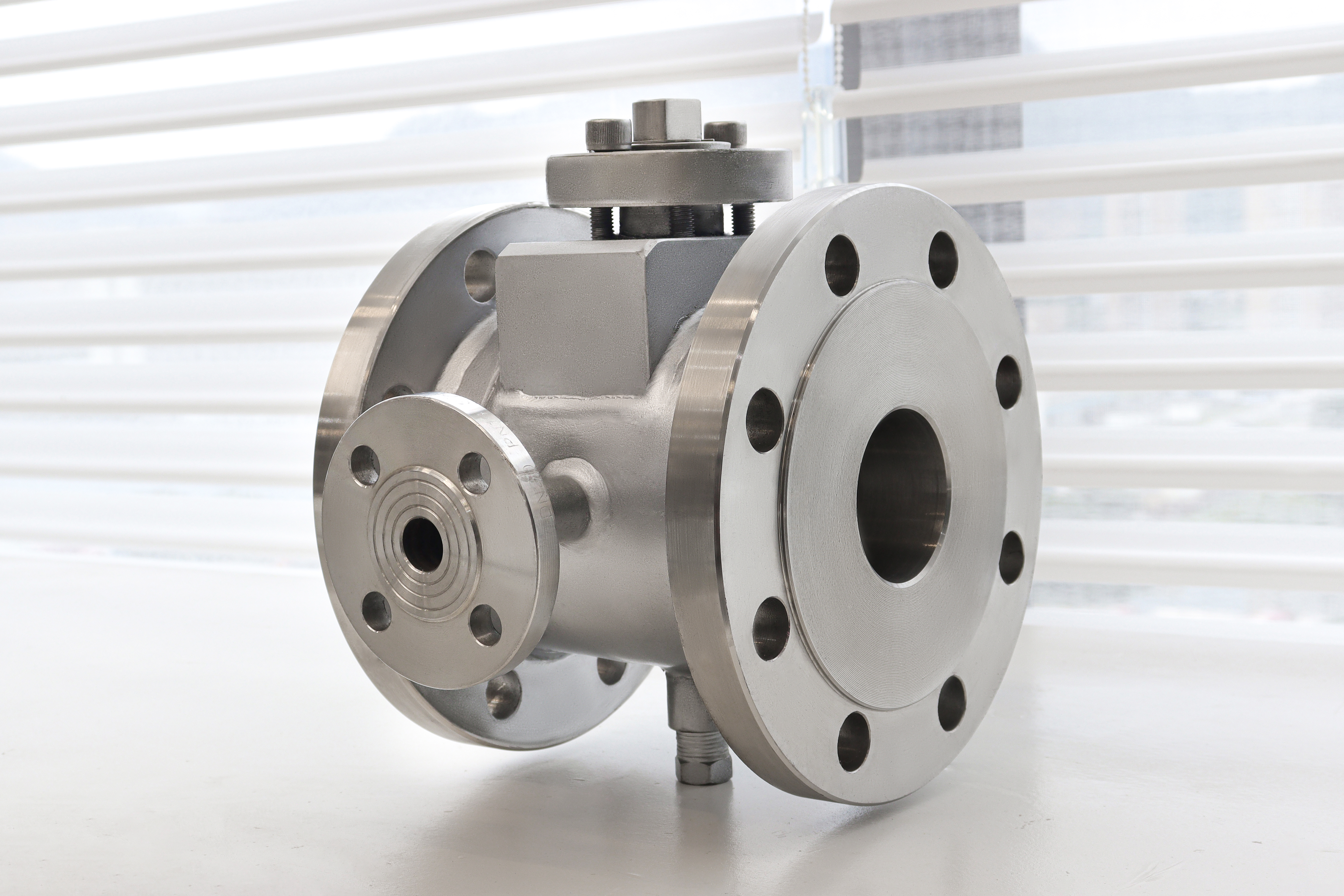
This is a floating ball valve with a second shell welded around the body. The valve itself is ordinary: a ball between two seat rings, a stem through the bonnet, flanged ends, Class 150 or 300, DN15 to DN200. The jacket is the part that changes the product. It is a full enclosure welded to the outside of the body, leaving a channel between the jacket and the body wall, and a heat transfer medium is pumped through that channel to hold the valve at temperature.
That construction exists for one reason: the medium sets solid or turns too thick to move when it cools. Bitumen, sulphur, resin, molasses, chocolate, tallow and heavy fuel oil all do this, and a valve that is warm when the plant runs becomes a plug when the line stops. The jacket keeps the body, the ball and both seat pockets above the setting point during a shutdown, so the valve can still be turned when the line restarts.
Design and Construction
The jacket is welded to the body, not cast with it, so the valve has two pressure boundaries rather than one. The inner boundary is the body and the bonnet, holding the line medium. The outer boundary is the jacket, holding the heat transfer medium at its own pressure and temperature. Each is tested separately, and each has its own limit; a jacket tested only as part of the body is not tested at all, because the two cavities are not connected.
The jacket has to cover the right area to be worth having. It runs over the body and around both seat pockets, because a jacket that heats only the middle of the body leaves the seats cold and the valve still sticks. The jacket ports are the other half of the design: their size and position are chosen at build time and cannot be moved later, and a port in the wrong place leaves a dead leg that will not drain or vent.
Material Options
The body is cast austenitic stainless, 304 or 316, and the jacket is 304 as standard. Stainless is the normal choice here not because the medium is corrosive but because the jacket medium usually is: steam condensate and heat transfer oil both attack carbon steel over years, and a jacket that rusts through puts heat medium into the process. The trim follows the body, with a 316 ball and a 316 stem.
The seat is the material that actually limits the valve. PTFE and RPTFE are the standard compounds and they sit well below the body grade ceiling, so the jacket temperature has to be chosen with the seat in mind rather than with the body in mind. Where the jacket runs hot, the seat moves to PPL or to a metal seat, and the price and the torque both go up at that point.
| Component | Standard Material | Optional Upgrade | Service Notes |
|---|---|---|---|
| Body | ASTM A351 CF8 or CF8M cast stainless | A182 F304 or F316 forged | two piece, bolted joint |
| Jacket | 304 stainless welded to the body | 316 where the heat medium demands it | full enclosure, separate pressure boundary |
| Ball | 316 stainless, ground and polished | hard chrome plated | floats against the downstream seat |
| Stem | 316 stainless | 17-4PH | blowout proof, anti static |
| Seat | PTFE | RPTFE, PPL, metal seat for high temperature | the part that caps the temperature |
| Packing | PTFE | flexible graphite | adjustable gland |
| Jacket ports | DN15 to DN50, RF or flat face | threaded where ordered | position fixed at build time |
| Body gasket | PTFE or spiral wound stainless | graphite where the temperature requires | renewed at every opening |
| Operator | Lever or handwheel | pneumatic, electric | pad and stem top machined for actuation |
Technical Specifications
The declared envelope is DN15 to DN200, Class 150 to 300, body and jacket in stainless, flanged ends to ASME B16.5 with a raised face, jacket ports DN15 to DN50 with RF or flat face, and a PTFE or RPTFE seat. Face to face follows ASME B16.10 for the size and class. The jacket adds width and weight to the body envelope, which matters in a tight pipe rack even though it does not change the face to face length.
The temperature field has to be written twice on any enquiry for this valve. One figure is the medium temperature, which sets the body grade and the seat compound. The other is the jacket medium and its temperature, which sets the jacket material, the port size and the seat again, from the other direction. A single figure quoted for both is the most common reason a jacketed valve arrives with the wrong seat.
| Item | Value |
|---|---|
| Nominal size | DN15 to DN200 (1/2 to 8 inch) |
| Pressure class | Class 150 to 300 (PN20 to PN50) |
| Body | ASTM A351 CF8 or CF8M cast stainless |
| Body option | A182 F304 or F316 forged |
| Body construction | two piece, one bolted joint |
| Jacket | 304 stainless, welded to the body |
| Jacket coverage | body and both seat pockets |
| Jacket design pressure | declared per order |
| Jacket design temperature | declared per order |
| Jacket ports | DN15 to DN50, RF or flat face |
| Jacket port position | side, top or bottom, fixed at build time |
| Ball | 316 stainless, ground and polished |
| Stem | 316 stainless, blowout proof |
| Seat | PTFE or RPTFE |
| Seat options | PPL, metal seat for high temperature |
| Packing | PTFE, adjustable gland |
| Packing option | flexible graphite |
| End connection | flanged RF to ASME B16.5 |
| Face to face | ASME B16.10 for the size and class |
| Bore | full bore |
| Operator | lever or handwheel |
| Operator options | pneumatic, electric |
| Design standard | ASME B16.34 and API 608 |
| Pressure test | API 598, shell 1.5 times, seat 1.1 times |
| Jacket test | separate test on the jacket cavity |
| Material certificate | EN 10204 3.1 per heat |
| Medium temperature | set by the process, capped by the seat compound |
| Jacket temperature | set by the heat transfer medium, declared per order |
| Anti static | spring loaded path from ball to stem to body |
| Marking | size, class, body grade, jacket rating, serial number |
Standards and Compliance
ASME B16.34 sets wall thickness and the pressure temperature rating for the body, and API 608 covers the general requirements for a flanged ball valve of this kind. Neither standard covers the jacket: the jacket is a pressure retaining part added by the manufacturer, and its design, its weld procedure and its test have to be declared by the maker and agreed with the buyer.
Two things therefore need to be on the order and not assumed. The jacket design pressure and temperature, because a jacket for a low pressure hot water loop and one for steam at pressure are not the same fabrication; and the test applied to the jacket, which should be a separate pressure test on the jacket cavity with the valve cavity open to atmosphere. A certificate that says only that the valve was shell tested has not covered the jacket.
| Requirement | Standard | What J-VALVES Supplies |
|---|---|---|
| Pressure boundary | ASME B16.34 | wall thickness and the pressure temperature rating |
| General ball valve requirements | API 608 | stem retention, marking, testing |
| Flanges | ASME B16.5 | raised face, Class 150 or 300 |
| Face to face | ASME B16.10 | for the size and class ordered |
| Jacket | declared by the manufacturer | design pressure, weld procedure and separate test |
| Pressure testing | API 598 | shell at 1.5 times, seat at 1.1 times |
| Jacket testing | separate test on the jacket cavity | valve cavity vented during the test |
| Material certificate | EN 10204 3.1 | body, jacket and trim per heat |
Manufacturing Process
The body is cast, solution annealed and machined, then the jacket is fabricated and welded onto it. The weld is the critical operation: it runs around the body in a closed path, it is made on a part that has already been machined, and heat from the weld must not distort the seat pockets or the flange facing. For that reason the jacket is welded before the final machining of the seat pockets wherever the geometry allows.
After welding, the jacket cavity is pressure tested on its own, and the whole assembly is then finish machined, assembled and tested as a valve. The jacket ports are fitted last, with their flange or thread facing cut after the welding heat has been put in, so that the port faces end up parallel to each other and square to the connection. A jacket welded after the final machining will pull the seat pockets out of square, which is why the sequence is fixed in the route card and not left to the fitter.

Quality Control and Testing
Every valve gets a shell test on the body cavity and a seat test in both directions, to API 598, and separately a pressure test on the jacket cavity. The jacket test is done with the valve cavity vented, so that a leak through the body wall shows up as a pressure drop on the jacket rather than being hidden by a common cavity. Dye penetrant on the jacket welds is normal for steam duty.
Two dimensional checks matter more on this product than on a plain valve. The jacket port centres are checked against the drawing, because a port that is ten millimetres out will not line up with the pipe that was already fabricated; and the overall width across the jacket is checked, because that is the dimension that decides whether the valve fits between the flanges and the insulation.
| Step | What Is Checked | Standard or Acceptance |
|---|---|---|
| Casting | chemical composition, radiography where specified | 3.1 certificate against the ordered grade |
| Jacket weld | procedure qualification, dye penetrant on the closed weld | weld map recorded against the serial number |
| Seat pockets | diameter, depth and squareness after welding | checked hot, after the jacket is on |
| Jacket cavity | separate pressure test with the valve cavity vented | no pressure drop over the hold time |
| Port faces | port centres, facing parallelism, square to the connection | drawing dimensions |
| Overall width | across the jacket, flange face to flange face | drawing dimension |
| Shell test | body cavity at 1.5 times the rating | API 598, no leak |
| Seat test | each seat in both directions at 1.1 times | API 598, no visible leak |
| Marking | size, class, body grade, jacket rating, serial number | read back against the certificate |

Applications and Industry Service
The duty is isolation on a line that must stay hot: bitumen and asphalt transfer, sulphur lines, resin and adhesive systems, food lines carrying fats, chocolate or syrup, heavy fuel oil forwarding, and any process where the medium has a pour point above ambient. It is also used where the medium crystallises rather than sets, such as urea and some salt solutions. In all of those duties the valve is a shutdown device, so it has to turn after weeks of standing cold, which is a harder test than working while the line runs.
It is the wrong valve where the medium does not need heat, because the jacket is a second pressure boundary and a second thing to maintain for no benefit. It is also the wrong choice where the seat temperature cannot be held below its ceiling: a jacket that has to run hot enough to keep the medium moving may be hot enough to take a PTFE seat out of its range, and the answer there is a different seat, not a hotter jacket.

Installation, Operation and Maintenance
Mount the valve so that the jacket ports can be vented at the top and drained at the bottom; a jacket that cannot be vented will air lock and heat only part of the body. Connect the jacket in parallel with the main trace heating loop rather than in series, so that one valve being isolated does not stop the flow to the rest of the line. Support the pipe independently; the jacket adds weight but no strength.
During a shutdown, keep the jacket circulating until the line has been drained, then drain the jacket as well if the plant will be down in freezing weather. When the valve is opened for a seat change, the jacket stays on the body and the side that is opened has to be clear of heat medium first. A jacket left full and cold is how these valves split a weld.
How to Specify and Order
An order needs the size, the class, the body grade, the seat compound, the end facing, the jacket material, the jacket design pressure and temperature, the jacket port size, the port facing and the port position. A typical line reads: DN50, Class 150, body and jacket 316, PTFE seat, RF flanged ends, jacket rated 10 bar at 180 degrees, two DN25 RF ports, one on each side.
State the medium and its temperature separately from the jacket medium and its temperature, and say whether the jacket will carry steam or oil, because that decides the jacket material and the weld details. If the valve will be insulated after installation, say so as well: the insulation thickness decides whether the lever or the actuator will still be reachable, and that is settled with an extended stem, not on site.
FAQ
Q: Why are there two temperatures on a jacketed valve?
A: Because the valve sees two. The medium temperature sets the body grade and the seat compound, and the jacket medium temperature sets the jacket material, the port size and the seat again from the other side. Heat travels from the jacket into the seat, so a jacket running hotter than the medium is what usually decides seat life. The two figures are quoted and checked separately.
Q: Is the jacket part of the pressure boundary?
A: It is a second pressure boundary, separate from the body. The body holds the line medium and the jacket holds the heat transfer medium, and the two cavities are not connected. Each is tested on its own, and a jacket that has only been covered by the body shell test has not been tested as a jacket at all.
Q: Where should the jacket ports be?
A: One low for draining and one high for venting, on the side that suits the pipe run. The position is fixed at build time and cannot be changed later, so it has to be settled against the actual pipe layout rather than left to the supplier. A port in the wrong place leaves a dead leg that will not drain, and the jacket then heats only part of the body.
Q: Can a jacketed valve be insulated after installation?
A: Yes, and it usually is, which is why the operator has to be thought about at the order stage. Insulation is applied over the jacket, so it also covers the bonnet and can bury the lever or the actuator. Where that is the case the stem is extended so the operator stays outside the insulation, and the extension length is a site dimension, not a catalogue one.
Q: Does the jacket work on a floating ball valve?
A: Yes, and the floating design suits it: a ball that is pushed into the downstream seat by the line pressure keeps sealing as the medium thickens, which is exactly the condition a jacketed line creates at a cold start. What the jacket must not do is cover only the middle of the body; it has to reach both seat pockets or the seats stay cold and the valve still sticks.
Q: What pressure should the jacket be rated for?
A: The maximum the heat transfer loop can reach, not the normal operating figure. Steam loops see the full supply pressure at the trap and can see more during a control failure, and heat transfer oil systems see the pump head. The jacket rating, the test pressure and the relief arrangement are all declared on the order for that reason.


Hot Products


News
Ball Valves in A Kraft Pulp Mill: Black Liquor, Green Liquor And The Cost of Choosing The Alloy by Habit
White liquor at pH 14 cracks carbon steel welds, black liquor sets solid below 100 C, green liquor dregs grind seats: alloy choice and torque in a kraft mill.
Read More
Slug Flow And Ball Valves: What Actually Arrives At The Seat
A slug is liquid mass with momentum, not a pressure spike. What changes at the seat, in the cavity and at the actuator when liquid reaches a ball valve.
Read More
Ball Valves in Direct Lithium Extraction: PH 1 Eluate, Gypsum Scale And 438,000 Cycles in Twenty-Five Years
Direct lithium extraction swings valves from pH 1 eluate to pH 12 caustic, 48 column switches a day and gypsum scale. Materials, seats and torque.
Read More
Ball Valves in Geothermal Brine: Silica Scale, Chloride Cracking And The Cooling Trap
Why geothermal brine destroys ball valves: retrograde silica scale, calcite at the flash point, chloride cracking above 60 C and the 250 C seat limit.
Read More