


CHINA J-VALVES Offers Various High-quality I ndustrial Ball Valves
J-VALVES, a distinguished professional ball valve manufacturer rooted in China, takes pride in its extensive product portfolio. Our offerings span a wide range, including trunnion-mounted ball valves, floating ball valves, high-temperature ball valves, high-pressure ball valves, metal-sealed ball valves, ultra-low temperature ball valves, DBB ball valves, Three-way And Four-way Ball Valve, and fully welded ball valves. Each product is a testament to our commitment to precision engineering and reliable performance. Meticulously crafted, they are designed to not only meet but exceed the most stringent industrial demands, ensuring stable operation even under extreme conditions. This enables us to provide our clients with high-value services and makes our valves widely sought-after in industries.
Product Category
Contact Us


-
J-VALVES-Q41F
-
J-VALVES
Overview of the J-VALVES 3 Inch 600LB WCB Two Piece Floating Ball Valve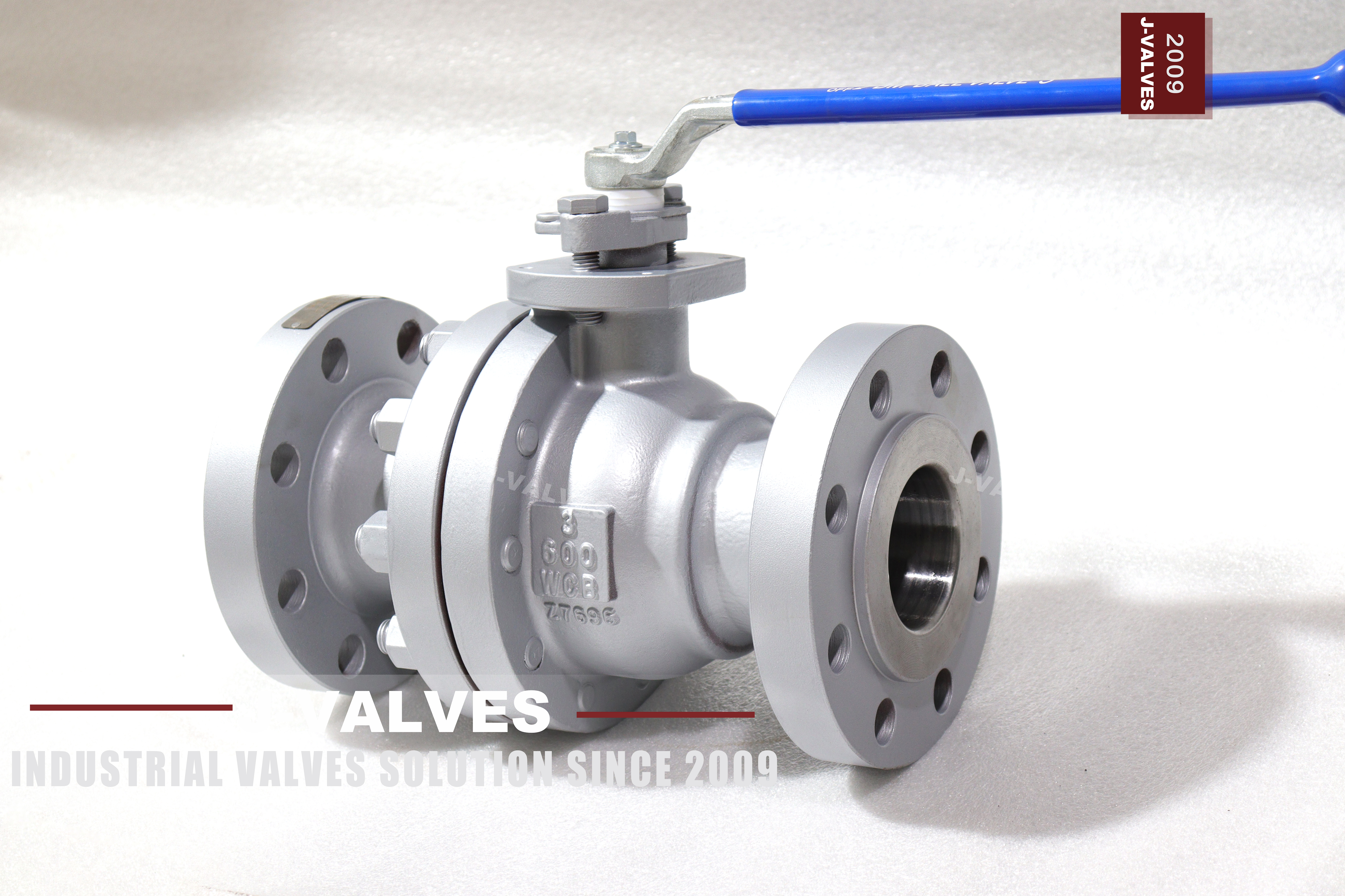
This is a three inch valve at the upper end of what a floating ball does well: DN80 bore, Class 600, which API 6D writes as PN100. The body is cast ASTM A216 WCB carbon steel in two bolted pieces, the ends are raised face flanges to ASME B16.5 Class 600, and the operator is a lever with a locking hole. It is a lever operated valve with a locking hole, and the bonnet is machined with a mounting pad for a small actuator if the line is automated later.
The ball floats, which means the pressure on its upstream half pushes the whole ball downstream until it presses on the outlet seat. That is the sealing mechanism, and it is also the reason the body joint matters more here than on a Class 150 valve: the same pressure that seals the seat also fills the cavity between the two seats and pushes outwards on the joint that closes the body.
So the part of this valve that deserves the attention is not the ball or the seat but the ring of studs and the gasket between the two body halves. At Class 600 that joint sees a pressure four times what it would see at Class 150, it has to stay tight through thermal cycles, and it is the one part of the valve a fitter can put back together wrongly.
Design and Construction
The ball sits between two seat rings with a little room to move, and the upstream seat does almost nothing while the valve is holding pressure. The seal is pressure assisted, so it improves as the pressure rises, which is why a floating valve is a good seal at Class 600 and why the operating torque also rises with the pressure rather than staying flat.
The two piece body has a single bolted joint on one side. The end piece comes off, the seat and the ball come out, and the second seat is reached from inside the centre section. One joint means one gasket and one ring of studs to get right, and it means the joint faces have to be flat and parallel, because a cast body that has been machined slightly out of square will leak there whatever the torque.
The joint is closed on a spiral wound gasket with a stainless hoop and a graphite filler, which is the right compromise at Class 600 between a sheet gasket that would be squeezed out and a ring joint that needs a different flange facing. The studs are B7 with 2H nuts, taken up in a cross pattern in at least two passes, and the faces are clean and dry before assembly because a lubricated gasket face changes the friction the torque figure assumes.
The stem passes through the bonnet, is retained so that it cannot be blown out, and drives the ball through a slot. A lever with a locking hole sits on top over a mounting pad, so the same valve can take a small pneumatic or electric actuator later. At DN80 and Class 600 the lever is still practical, which is the practical definition of where floating stops being the cheap answer.

Material Options
WCB is the body grade: cast carbon steel, normalised, rated from minus 29 to plus 425 degrees Celsius, and the default for water, oil, gas, steam condensate and non aggressive chemicals at this class. Being a casting, it can be radiographed and repaired within the rules of the standard, and it is cheaper than a forging at DN80 in the quantities these valves are usually bought.
The trim is stainless: ball in CF8 or CF8M with a hardened surface, stem in 304 or 316 stainless, seat in RPTFE as standard or PTFE where a softer seat is wanted. The ball and stem are the parts that wear, and specifying CF8M rather than CF8 is the usual upgrade when the medium is slightly corrosive but not aggressive enough to justify a stainless body.
| Component | Standard Material | Optional Upgrade | Service Notes |
|---|---|---|---|
| Body and end piece | ASTM A216 WCB cast carbon steel | A350 LCB for low temperature | two pieces, one bolted joint |
| Ball | A351 CF8 with a hardened surface | CF8M | floating, one sealing face at a time |
| Stem | A276 304 stainless | 316, 17-4PH | blowout proof, keyed to the ball |
| Seat ring | RPTFE | PTFE | sets the temperature limit |
| Body gasket | Spiral wound, stainless hoop, graphite filler | PTFE envelope | new gasket at every joint opening |
| Packing | PTFE V-ring | Flexible graphite | fire safe configuration |
| Body studs | ASTM A193 B7 with A194 2H nuts | B7M with 2HM | cross pattern, two or three passes |
| Operator | Lever with locking hole | Worm gear, pneumatic, electric | mounting pad on the bonnet |
Technical Specifications
The envelope is DN80, Class 600, two piece cast body in WCB, raised face flanges to ASME B16.5, face to face to ASME B16.10, lever with a locking hole, and pressure testing to API 598. The body joint is closed on a spiral wound gasket and the bolting is B7 with 2H nuts unless another grade is specified. The drawing states the flange drilling and the face to face length, and those two are what the pipe has to match when the valve arrives.
Two things are worth settling at the enquiry. The first is the seat compound against the line temperature, because the body will take far more heat than the seat and it is the seat that fails first. The second is whether the valve will be actuated, because the mounting pad and the stem top are machined at build time and a valve supplied without them cannot be converted cheaply later.
| Item | Value |
|---|---|
| Nominal size | 3 inch (DN80) |
| Pressure class | Class 600 (PN100) |
| Body construction | two piece, one bolted joint |
| Ball support | floating, no trunnion |
| Body material | ASTM A216 WCB cast carbon steel |
| Body option | A350 LCB for low temperature |
| Material group | ASME B16.34 group 1.1 carbon steel |
| Rating at 38 C | Class 600 = 102.1 bar |
| Temperature range | minus 29 to plus 425 C for WCB |
| Ball | A351 CF8 with a hardened surface |
| Ball option | CF8M |
| Stem | A276 304 stainless |
| Stem options | 316, 17-4PH |
| Seat | RPTFE |
| Seat option | PTFE |
| Packing | PTFE V-ring |
| Packing option | flexible graphite |
| Body gasket | spiral wound with stainless hoop and graphite filler |
| Body studs | ASTM A193 B7 with A194 2H nuts |
| Stud option | B7M with 2HM |
| Bore | full port, DN80 |
| End connection | raised face flange to ASME B16.5 Class 600 |
| Face to face | ASME B16.10 |
| Wall thickness | ASME B16.34 |
| Design standards | ASME B16.34 and API 608 |
| Pressure testing | API 598 shell and seat, both directions |
| Operator | lever with locking hole |
| Actuation options | worm gear, pneumatic, electric |
| Anti static | spring loaded path from ball to stem to body |
| Marking | size, class, WCB and heat number on the body |
| Documentation | EN 10204 3.1, test record, general arrangement drawing |
Standards and Compliance
ASME B16.34 sets the wall thickness and the pressure temperature rating. WCB is carbon steel in material group 1.1: Class 600 corresponds to 102.1 bar at 38 degrees, and the group is rated to 425 degrees, above which graphitisation rather than wall strength limits the valve. API 608 covers the ball valve specifics, including the anti static path and the blowout proof stem. Where the same valve is ordered for a European pipeline, the flange drilling changes and the rest of the valve does not, which is why the drilling is a line on the order rather than an assumption.
The flanges are to ASME B16.5 Class 600, which at DN80 gives a specific bolt circle and thickness that differ from both the Class 300 and the PN100 European pattern. That last point is worth stating: PN100 and Class 600 are the same rating step, but a PN100 flange and a Class 600 flange do not bolt together, and the order has to say which one is wanted.
| Requirement | Standard | What J-VALVES Supplies |
|---|---|---|
| Wall thickness and rating | ASME B16.34 | group 1.1 carbon steel, Class 600 = 102.1 bar at 38 C |
| Ball valve specifics | API 608 | anti static path, blowout proof stem, nameplate |
| Flanges | ASME B16.5 | Class 600 raised face; PN100 is a different bolt circle |
| Face to face | ASME B16.10 | flanged pattern for DN80 Class 600 |
| Pressure testing | API 598 | shell at 1.5 times, seat at 1.1 times, both directions |
| Material certificate | EN 10204 3.1 | certificate per heat |
Manufacturing Process
The body and end piece are cast, heat treated and machined, with the bore, the seat pocket and the joint face cut in one setting. The joint face is then checked for flatness and parallelism, because on a two piece valve that face is the pressure boundary and a machining error there cannot be corrected by tightening the studs harder. All of that is done before the parts are painted, because a joint face that is painted or coated will not seal and the error is invisible once the valve is assembled.
The ball is machined, ground and lapped, then surface hardened, and checked for roundness against the seat rings. Assembly is the body on the bench, seats in, ball in, the end piece on with a new gasket, studs taken up in a cross pattern in two or three passes to the specified torque, then the stem, the packing, and the lever with its locking plate set so it engages at both open and closed.

Quality Control and Testing
Casting soundness is checked on the pressure retaining areas and around the joint, and the heat is certified with composition and mechanical properties. The machined joint face is checked for flatness, the flange facing and drilling against ASME B16.5, the bore against DN80, and the thread or the stem key against the drawing. Every figure on the record is traceable to a gauge or a certificate, and the record is issued with the valve rather than filed at the works.
Every valve is shell tested at one and a half times the rating and seat tested at one point one times, to API 598, with the body joint watched separately from the seats. The seat test is run in both directions because a floating valve only seals on the downstream side, and the breakaway torque is measured and recorded so an actuator can be sized from a number rather than from an estimate.
| Step | What Is Checked | Standard or Acceptance |
|---|---|---|
| Casting | soundness on pressure retaining areas and around the joint | visual and radiographic where specified |
| Machining | joint face flatness and parallelism, seat pocket squareness | drawing tolerance, measured on the face |
| Flange | facing, drilling, bolt circle, thickness | ASME B16.5 Class 600 |
| Ball | roundness, surface finish, hardness after hardening | drawing range |
| Body joint | gasket, stud grade, tightening sequence and final torque | specified torque in a cross pattern |
| Shell test | body and joint at 1.5 times | API 598, no leak |
| Seat test | each seat in both directions at 1.1 times | API 598, no visible leak |
| Torque | breakaway torque on the assembled valve | recorded and issued with the drawing |

Applications and Industry Service
The duty is isolation on medium pressure water, oil, gas and steam condensate lines: plant utilities, boiler feedwater and condensate, compressed air, fire protection where a carbon steel body is accepted, and general process isolation at sizes where a three inch line is the branch rather than the main. Most of these valves are operated occasionally and replaced rather than repaired. In all of those the valve is bought against a line size and a pressure class rather than against a process specification, and the body grade follows from the medium.
It is not a throttling valve and not a valve for aggressive media, where the carbon steel body will corrode long before the trim wears. It is also not the right choice above the temperature band of the seat, and on a line that cycles hot and cold often, a two piece body joint needs more attention than a welded body would. Those three limits, temperature, medium and cycling, are what decide whether a two piece carbon steel valve is the right purchase or a false economy.

Installation, Operation and Maintenance
Support the pipe on both sides so the valve is not carrying the line, and check that the flanges are parallel before the studs are drawn up. On a valve that has been opened for maintenance, the body joint goes back together with a new gasket and the specified torque in a cross pattern; reusing a compressed spiral wound gasket is how a valve that passed its test in the works starts weeping in the plant.
Operate a quarter turn, fully open or fully closed, and lock the lever in position where the procedure requires it. If the lever becomes stiff, the cause is usually a deposit on the ball or a swollen seat, and the answer is to open the body and look rather than to fit a longer handle. A lever that has been extended is a stem waiting to twist.
How to Specify and Order
Write the size, the class, the body grade, the ball and stem grade, the seat, the facing and the operator. A typical line reads: three inch, Class 600, body A216 WCB, ball CF8M, stem 316, RPTFE seat, raised face flanges to ASME B16.5, lever with locking hole. Add the medium and the temperature, because the temperature decides the seat. If the valve replaces an existing one, send the old nameplate details, because a change of flange drilling or face to face is the most common reason a replacement does not fit.
Say whether the valve will be actuated and whether the line will be insulated, because the first changes the bonnet and the stem top and the second may call for an extended stem. Both are cheaper to add at the order than to retrofit, and neither can be inferred from the size and the class alone. Those two answers also decide whether the valve needs an extended stem, which is a separate product rather than an accessory.
FAQ
Q: Why does the body joint matter so much at Class 600?
A: Because it is the part of the valve that sees the most pressure and the least attention. The cavity between the two seats fills at line pressure and pushes outwards on the joint, so the studs and the gasket are holding the valve together, not just holding a cover on. At Class 600 that load is substantial, and the joint is also the one thing a fitter can reassemble wrongly.
Q: Can a three inch valve still be operated by hand?
A: At Class 600, yes, and this is roughly where that stops being comfortable. The pressure acts on a three inch ball, so the seat load and the breakaway torque are still within what a lever can deliver, but a longer lever is not the answer if it becomes stiff: that usually means a deposit or a swollen seat. Above this size and class, a trunnion valve and a gearbox become the practical choice.
Q: Which gasket goes in the body joint?
A: A spiral wound gasket with a stainless hoop and a graphite filler, which suits Class 600 and the temperature band of a WCB valve. A sheet gasket can be squeezed out at this pressure, and a ring type joint needs a different flange facing. The gasket is replaced every time the joint is opened, and the faces are cleaned before it goes back.
Q: Is PN100 the same as Class 600?
A: As a rating step, yes: API 6D lists PN100 against Class 600, and Class 600 is 102.1 bar at 38 degrees. As flanges they are not interchangeable, because a PN100 flange to EN 1092-1 and a Class 600 flange to ASME B16.5 have different bolt circles and thicknesses. This valve is drilled to ASME B16.5, and the order has to say so.
Q: What is the temperature limit?
A: Minus 29 to plus 425 degrees Celsius for the WCB body, and less for the seat: RPTFE to about 180 degrees and PTFE to about 150. The body will take more heat than the seat, so in practice the seat compound sets the limit. Above 425 degrees the body would need a low alloy grade rather than a thicker wall.
Q: Can it be actuated?
A: Yes, where the bonnet was machined with the mounting pad and the stem top with a drive. A small pneumatic or electric actuator then mounts over the pad in place of the lever. Order it as a build rather than adding it later, because a valve supplied for manual operation has no pad and no drive, and converting it means changing the bonnet.


Hot Products


News
Ball Valves in A Kraft Pulp Mill: Black Liquor, Green Liquor And The Cost of Choosing The Alloy by Habit
White liquor at pH 14 cracks carbon steel welds, black liquor sets solid below 100 C, green liquor dregs grind seats: alloy choice and torque in a kraft mill.
Read More
Slug Flow And Ball Valves: What Actually Arrives At The Seat
A slug is liquid mass with momentum, not a pressure spike. What changes at the seat, in the cavity and at the actuator when liquid reaches a ball valve.
Read More
Ball Valves in Direct Lithium Extraction: PH 1 Eluate, Gypsum Scale And 438,000 Cycles in Twenty-Five Years
Direct lithium extraction swings valves from pH 1 eluate to pH 12 caustic, 48 column switches a day and gypsum scale. Materials, seats and torque.
Read More
Ball Valves in Geothermal Brine: Silica Scale, Chloride Cracking And The Cooling Trap
Why geothermal brine destroys ball valves: retrograde silica scale, calcite at the flash point, chloride cracking above 60 C and the 250 C seat limit.
Read More