


CHINA J-VALVES Offers Various High-quality I ndustrial Ball Valves
J-VALVES, a distinguished professional ball valve manufacturer rooted in China, takes pride in its extensive product portfolio. Our offerings span a wide range, including trunnion-mounted ball valves, floating ball valves, high-temperature ball valves, high-pressure ball valves, metal-sealed ball valves, ultra-low temperature ball valves, DBB ball valves, Three-way And Four-way Ball Valve, and fully welded ball valves. Each product is a testament to our commitment to precision engineering and reliable performance. Meticulously crafted, they are designed to not only meet but exceed the most stringent industrial demands, ensuring stable operation even under extreme conditions. This enables us to provide our clients with high-value services and makes our valves widely sought-after in industries.
Product Category
Contact Us


-
J-VALVES-Q347F
-
J-VALVES
Overview of the J-VALVES DN50x40 Class 1500 Extended Stem Ball Valve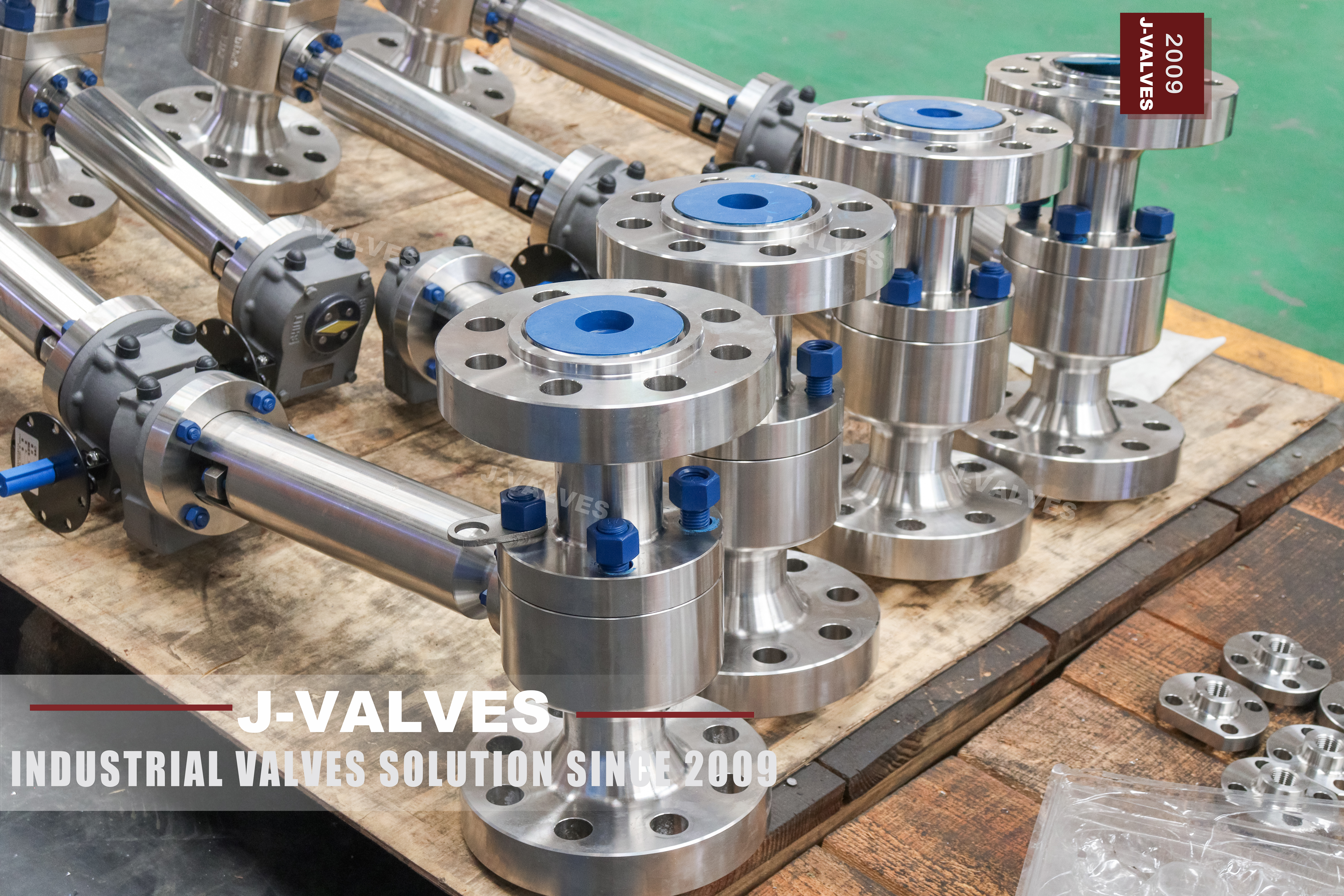
This is a two piece floating ball valve at Class 1500 with a two inch flange and a one and a half inch bore, a forged F44 body and an extended stem. DN50 is the body size, DN40 is the bore, the ends are flanged raised face or ring joint, and the body is forged A182 F44, the super austenitic stainless designated UNS S31254. The extension raises the operator above the body so the valve can be insulated or buried without burying the lever as well.
The extended stem is the part of this valve that is most often misunderstood, and the misunderstanding is worth clearing before the specification is written. On this body the packing stays where it always was, in the body and around the stem at the gland; the extension is a piece of stem above the gland, not a bonnet and not a second pressure boundary. The pressure still stops at the packing in the body, and the extension only changes where the operator stands.
Design and Construction
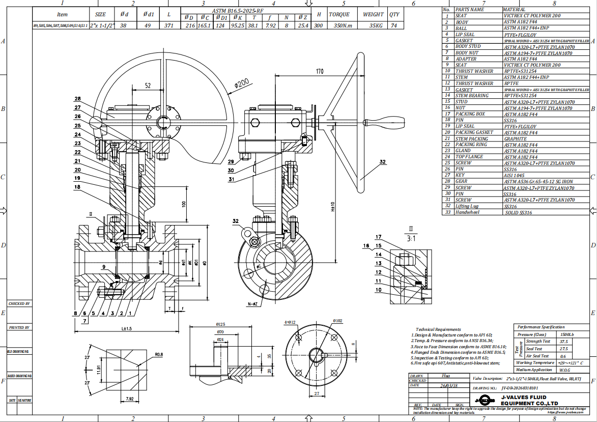
The stem passes through the body top, is sealed by the packing and the gland, and is retained against blowout by a shoulder that bears on the body. Above the gland, an extension piece is coupled to the stem and carries the lever or the gear up to the working height. Because the packing is below the coupling, servicing the gland does not disturb the extension and adjusting the extension does not disturb the seal, which is the practical advantage of the arrangement.
The extension is a mechanical part with a mechanical problem: it is a lever arm hanging off a small stem. A long unsupported extension flexes under hand effort, and the side load goes into the stem and the packing rather than into the ball. That is why an extension above a certain length needs a bracket that takes the reaction back to the body or to a stand, and why the length should be fixed by the insulation thickness or the burial depth rather than chosen as the longest available.
Material Options
The body is forged A182 F44, which is UNS S31254, a super austenitic stainless with a high molybdenum content and a high enough prealloyed nitrogen level to give it a high pitting resistance. It is chosen for chloride bearing product, seawater-adjacent service and aggressive chemical lines where 316 is not enough and a duplex is not wanted. The designation on the certificate is A182 F44 and UNS S31254; the mill trade names that circulate in the market are not material grades and should not appear on a specification.
The trim follows the body. The ball is F44 with hard chrome or a nitrided surface; the stem is F44 or 17-4PH; the seat is RPTFE, PEEK or PPL, with a metal seat available where the class makes a soft seat marginal. A code sometimes written as F44L for a low carbon variant is not a grade that exists in ASTM A182, so it should not be ordered and it does not appear on this page as an option.
| Component | Standard Material | Optional Upgrade | Service Notes |
|---|---|---|---|
| Body and end cap | ASTM A182 F44 forged, UNS S31254 | A182 F316 for lower chloride duty | F44 for chloride bearing and aggressive product |
| Ball | F44 with hard chrome or nitrided | F316 with hard chrome | coating decides life on abrasive product |
| Stem | F44 | 17-4PH precipitation hardening | blowout proof, retained by the body |
| Seat ring | RPTFE | PEEK, PPL, metal with cobalt alloy facing | soft seat is marginal at this class |
| Body gasket | Spiral wound, PTFE or graphite filled | Ring joint to ASME B16.20 on RTJ facing | replaced every time the body is opened |
| Stem packing | PTFE V-ring | Graphite for higher temperature | the packing stays in the body, not in the extension |
| Extension | F44, length to the order | Bracket and stand for long extensions | sets where the operator stands, not the pressure boundary |
| Operator | Lever | Worm gear, pneumatic, electric, hydraulic | gear where the measured torque needs it |
Technical Specifications
The envelope is DN50 by DN40, Class 1500 which is PN250, two piece forged body, flanged to ASME B16.5 in raised face or ring joint form, with a reduced bore of DN40 inside a DN50 body. Class 1500 floating valves are a small family: above this class the seat load on a floating ball becomes impractical and a trunnion design takes over, so this valve sits near the top of what the construction can do.
PN250 is the correct pressure designation and it is worth stating why. API 6D lists seven pressure codes and the one for Class 1500 is PN250, and EN 1092-1 also carries PN250. A figure of PN260 appears on some data sheets, including the original version of this page, and it does not exist in either standard; it looks like a bar rating converted and rounded. The pipe will be flanged to PN250 or to Class 1500, and a valve marked to a number that is in no table creates a documentation problem at inspection.
| Item | Value |
|---|---|
| Body size | DN50 (2 inch) |
| Bore | DN40 (1.5 inch), reduced bore |
| Pressure rating | Class 1500 (PN250) |
| Pressure note | PN260 appears in no standard; the code for Class 1500 is PN250 |
| Body construction | two piece, bolted end cap |
| Ball support | floating, no trunnion |
| Body material | ASTM A182 F44 forged, UNS S31254 |
| Body option | A182 F316 for lower chloride duty |
| Ball | F44 with hard chrome or nitrided |
| Stem | F44 |
| Stem option | 17-4PH precipitation hardening stainless |
| Seat | RPTFE |
| Seat options | PEEK, PPL, metal with cobalt alloy facing |
| Packing | PTFE V-ring |
| Packing location | in the body gland, below the extension |
| Extension | F44, length set by insulation or burial depth |
| Extension support | bracket and stand for long extensions |
| End connection | flanged raised face or ring joint to ASME B16.5 |
| Face to face | ASME B16.10 |
| Wall thickness | ASME B16.34 |
| Design standard | API 6D and API 608 |
| Pressure testing | API 598 shell and seat, both directions |
| Operator | lever as standard |
| Operator options | worm gear, pneumatic, electric, hydraulic |
| Anti static | spring loaded path from body to stem to ball |
| Stem retention | blowout proof, retained by the body |
| Body cavity | self relieving through the seat |
| Fire safe | API 607 / ISO 10497 where required |
| Marking | size, class, F44 and heat number on the nameplate |
| Documentation | EN 10204 3.1, test record, GA drawing with the extension length |
Standards and Compliance
The design follows API 6D where pipeline documentation is required and API 608 for the ball valve specifics, with ASME B16.34 supplying the wall and the rating, ASME B16.5 the flange, ASME B16.10 the face to face length and API 598 the pressure test. At Class 1500 the wall calculation and the joint design carry more weight than at low pressure, because the same body sections have to hold a much higher load and the bolted joint is a pressure boundary rather than a locating feature.
Two project standards often decide the order. NACE MR0175 / ISO 15156 applies where the product contains wet H2S and constrains the hardness of the trim; API 607 or ISO 10497 applies where a fire safe certificate is required. On a Class 1500 valve the certificate matters more than on a low pressure one, because the consequence of a seal failure at this class is different and the documentation is usually a contractual deliverable rather than a nice to have.
| Requirement | Standard | What J-VALVES Supplies |
|---|---|---|
| Pipeline valve requirements | API 6D | design document, GA drawing, test record |
| Ball valve specifics | API 608 | anti static path, blowout proof stem, nameplate content |
| Wall thickness and rating | ASME B16.34 | wall calculation for DN50 Class 1500 |
| Pressure designation | API 6D clause 7.2 and EN 1092-1 | Class 1500 is PN250, not PN260 |
| Flange dimensions and facing | ASME B16.5 | raised face or ring joint as ordered |
| Face to face length | ASME B16.10 | length confirmed on the drawing |
| Ring joint gasket where used | ASME B16.20 | gasket supplied with the valve |
| Pressure testing | API 598 | shell at 1.5 times, seat at 1.1 times, both directions |
| Wet H2S service | NACE MR0175 / ISO 15156 | hardness control on the trim |
| Fire safe where required | API 607 / ISO 10497 | certificate naming seat and packing |
| Material certificate | EN 10204 3.1 | F44 declared as A182 F44 and UNS S31254 |
Manufacturing Process
The body is forged in two sections, then machined so the joint faces stay parallel and square to the bore. On a Class 1500 body the joint is the part that has to be right, and a face that is out of parallel will leak however much the studs are pulled, so the faces are checked on a surface plate rather than with a straightedge. The seat pockets are machined, the stem bore is drilled and reamed square to the seat axis, and the gland threads are cut last.
The extension is machined separately and coupled to the stem with a cross pin or a keyed joint, and the coupling is the part that has to be concentric. An extension that is a few tenths off centre puts a permanent side load on the packing and is the usual reason an extended stem valve weeps at the gland. On a bracketed build the bracket is fitted to the body and the extension is aligned to the stem before the coupling is pinned, not after.

Quality Control and Testing
Each valve is shell tested at one and a half times the rating and seat tested at one point one times in both directions to API 598. At Class 1500 the shell test is the one that finds a body or a joint problem, and the seat test is the one that finds a seat or a ball problem, so both are run and both are recorded per valve rather than per batch. The stem seal is checked at rated pressure with the extension fitted, because the extension changes the load path into the gland.
The dimensional checks include the things that are specific to this build: the extension length against the insulation thickness or the buried depth stated on the order, the concentricity of the coupling, the runout at the top of the extension, and the alignment of the bracket where one is fitted. The torque is measured on the assembled valve with the extension in place, because a long extension adds friction at the gland and a torque measured without it is optimistic.
| Step | What Is Checked | Standard or Acceptance |
|---|---|---|
| Incoming material | heat number and grade against the mill certificate | EN 10204 3.1, A182 F44 confirmed, no trade name substitution |
| Forging | ultrasonic check on the pressure boundary sections | no indication above the acceptance level |
| Joint faces | parallelism and squareness to the bore | surface plate check, drawing tolerance |
| Seat pockets | squareness to the stem axis | drawing tolerance, checked after machining |
| Extension coupling | concentricity and pin fit | runout at the top of the extension within drawing tolerance |
| Shell test | body and both joints at 1.5 times Class 1500 | API 598, no leak, no permanent distortion |
| Seat test | each seat in both directions at 1.1 times | API 598, no visible leak |
| Gland with extension fitted | stem seal at rated pressure | no weep at the gland over the hold time |
| Torque | breakaway and running torque with the extension in place | recorded, issued with the drawing |
| Marking | nameplate against the order | size, Class 1500, F44, heat number |

Applications and Industry Service
The build is for lines that are insulated or buried and where the operator has to stay accessible. Cold box and cryogenic piping, insulated hot oil and steam traced lines, buried water and fuel lines, and tank farm lines under a insulated jacket all put the valve body out of reach and the handle out of reach with it. The extension brings the lever or the gear back to a height a person can use without removing insulation.
The F44 body adds the corrosion case. Chloride bearing process streams, brackish and seawater adjacent cooling, bleach and hypochlorite lines and aggressive chemical transfer are where a super austenitic body is chosen over 316, and where the extension is usually there for a different reason, namely that the line is insulated to keep the product at temperature. The two requirements often arrive together on the same valve.

Installation, Operation and Maintenance
Fit the valve with the extension vertical where possible, because a horizontal extension is a cantilever and loads the gland in a direction it was not designed for. Fit the bracket where one is supplied and do not use the extension as a handle to lift the valve or to align the flanges. Leave the insulation clear of the coupling so that the gland can be adjusted without stripping the jacket, which is the whole point of paying for the extension.
Do not use the extension to apply more force than the stem was designed for: the extra length gives leverage that the stem and the packing did not ask for, and a valve that will not turn at Class 1500 is a seat or a pressure problem rather than a lever problem. Check the gland for weep at commissioning and after the first thermal cycle, and re-torque the packing rather than the coupling if the extension shows runout.
How to Specify and Order
State body size and bore, class, body grade, ball and seat trim, flange facing, face to face standard, extension length, whether a bracket is required, and the operator. For this valve a typical line reads: DN50 by DN40, Class 1500, A182 F44 forged body, ball F44 with hard chrome, PEEK seat, ring joint to ASME B16.5, face to face to ASME B16.10, extended stem to suit the stated insulation thickness, worm gear.
Send the insulation thickness or the burial depth, because that is what sets the extension length, and send the fluid and the chloride level, because that is what decides whether F44 is needed or whether 316 will do. If the line is traced or the valve is in a cold box, say so: the temperature at the operator, not at the body, is what decides whether the lever needs an extended handle or the valve needs actuation instead.
FAQ
Q: Is the extended stem part of the pressure boundary?
A: No. The packing stays in the body gland and the pressure stops there. The extension is a piece of stem above the gland that brings the lever or the gear up to a working height, so servicing the gland does not disturb it and adjusting it does not disturb the seal. Treating it as a bonnet, or as a second seal, is the most common misunderstanding about this build.
Q: How long should the extension be?
A: As long as the insulation thickness or the buried depth requires, and no longer. The length is set by the order rather than chosen from a list, because a longer extension than necessary adds a cantilever load to the stem and the packing for no benefit. Above a certain length a bracket is fitted to take the reaction back to the body.
Q: Is PN260 the same as Class 1500?
A: Class 1500 is PN250. API 6D lists seven pressure codes and the one for Class 1500 is PN250, and EN 1092-1 also carries PN250. PN260 does not appear in either standard; it looks like a bar rating converted and rounded. A valve marked to a number that is in no table creates a documentation problem at inspection.
Q: What is F44 and can I write 254SMO on the order?
A: F44 is the ASTM A182 designation for UNS S31254, a super austenitic stainless with high molybdenum and nitrogen. The names that circulate in the market for this family are mill trade names, not grades, so a specification should say A182 F44 or UNS S31254 and a certificate should confirm one of those. A trade name on a drawing does not define what is delivered.
Q: Is there an F44L grade?
A: No. A low carbon variant written as F44L does not exist in ASTM A182, so it cannot be certified and should not appear as an option on a data sheet. Where a lower carbon content is wanted for welding, that is a conversation with the mill about the delivered analysis, not a grade that can be ordered by adding a letter.
Q: Why is the bore DN40 in a DN50 body?
A: Because at Class 1500 a full port DN50 floating valve puts a large area under pressure onto the seat and the torque becomes impractical. Reducing the bore to DN40 cuts that area and keeps the valve operable, which is why high pressure floating valves are usually reduced bore. The trade off is a higher pressure drop and no pig passage.


Hot Products


News
Ball Valves in A Kraft Pulp Mill: Black Liquor, Green Liquor And The Cost of Choosing The Alloy by Habit
White liquor at pH 14 cracks carbon steel welds, black liquor sets solid below 100 C, green liquor dregs grind seats: alloy choice and torque in a kraft mill.
Read More
Slug Flow And Ball Valves: What Actually Arrives At The Seat
A slug is liquid mass with momentum, not a pressure spike. What changes at the seat, in the cavity and at the actuator when liquid reaches a ball valve.
Read More
Ball Valves in Direct Lithium Extraction: PH 1 Eluate, Gypsum Scale And 438,000 Cycles in Twenty-Five Years
Direct lithium extraction swings valves from pH 1 eluate to pH 12 caustic, 48 column switches a day and gypsum scale. Materials, seats and torque.
Read More
Ball Valves in Geothermal Brine: Silica Scale, Chloride Cracking And The Cooling Trap
Why geothermal brine destroys ball valves: retrograde silica scale, calcite at the flash point, chloride cracking above 60 C and the 250 C seat limit.
Read More