


CHINA J-VALVES Offers Various High-quality I ndustrial Ball Valves
J-VALVES, a distinguished professional ball valve manufacturer rooted in China, takes pride in its extensive product portfolio. Our offerings span a wide range, including trunnion-mounted ball valves, floating ball valves, high-temperature ball valves, high-pressure ball valves, metal-sealed ball valves, ultra-low temperature ball valves, DBB ball valves, Three-way And Four-way Ball Valve, and fully welded ball valves. Each product is a testament to our commitment to precision engineering and reliable performance. Meticulously crafted, they are designed to not only meet but exceed the most stringent industrial demands, ensuring stable operation even under extreme conditions. This enables us to provide our clients with high-value services and makes our valves widely sought-after in industries.
Product Category
Contact Us


-
J-VALVES-Q41F
-
J-VALVES
Overview of the J-VALVES 0.75 x 0.5 in PN20 Two Piece Stainless Steel Floating Ball Valve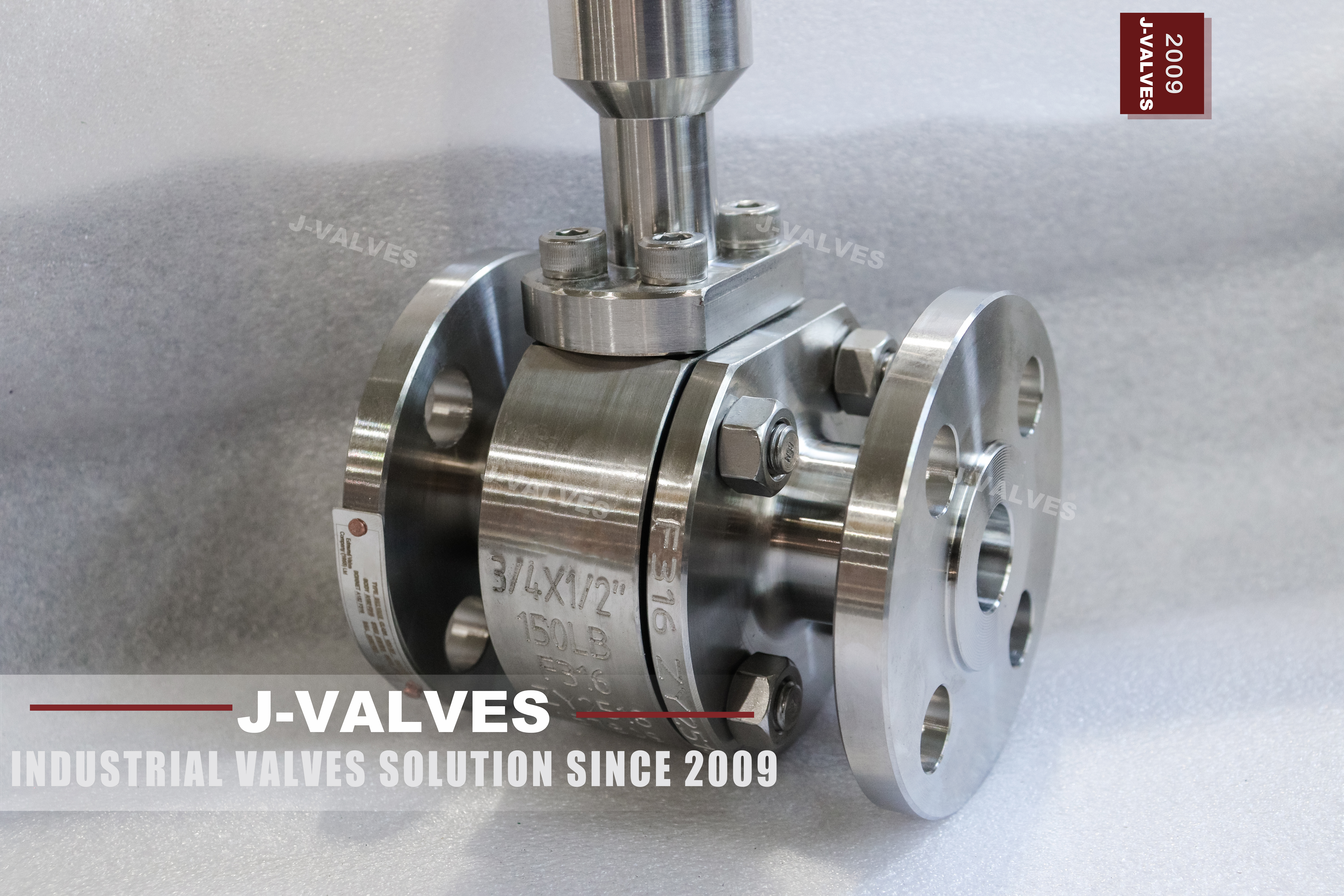
This is a two piece side entry ball valve with a cast austenitic stainless steel body, a reduced port and a soft seat, rated PN20 and flanged to ASME B16.5 raised face. The 0.75 x 0.5 in callout does not mean that the two ends are different sizes: both flanges are three quarter inch, DN20, and the 0.5 in refers to the bore through the ball, which is DN15. That single distinction is the most misread part of the description and it decides what the valve can be used for, so it is worth stating before anything else. The extension on the stem is a separate item again, and it does not change the pressure boundary.
The valve is built to ASME B16.34 for its ratings and to API 608 as the product standard for flanged steel ball valves, tested to API 598. PN20 is the API 6D designation that corresponds to Class 150, which means the same class can be written either way and the ASME B16.34 rating for a group 2.2 material at 38 C is 19.6 bar. What the valve does not have is equally important: there are no trunnions, no bearings, no cavity port, no double block and bleed and no double piston effect seats. Those are features of a trunnion mounted body and none of them exist here.
The extended stem is supplied where the operator has to reach the valve from outside something: insulation cladding on a traced line, a buried run, a pit, or a low point under a rack where a standard lever would end up inside the lagging. Buyers for this size are usually specifying a small bore stainless line on a skid, a sample point, an instrument air branch or a dosing run, and they want the handle to end up somewhere an operator can actually stand.
Design and Construction
The body is split into a main body and one end cap, held together by studs with a gasket at the joint. There is one pressure retaining joint in this design, not two, which is the reason the two piece pattern dominates at this size rather than the three piece. A three piece body has two such joints and two sets of studs, and on a DN20 valve the middle section is small enough that the extra joint buys nothing that the two piece does not already give, while adding a second place to leak and a second set of fasteners to torque.
The ball in this valve is not carried on trunnions. It sits between two seat rings and is free to move axially, and the only thing that loads the downstream seat is the pressure difference across the ball acting on the seat annulus. There is no independent seat preload and no spring behind the seat unless one is specified as an option. This is the whole mechanism, and it explains both the strength and the weakness of the design: the higher the differential, the harder the ball is pressed into the seat, and near zero differential there is almost nothing pressing at all. A floating ball is not a defect at low pressure; it is the design behaving as designed, and it is why a gas tightness figure has to be stated in the enquiry rather than inferred from the class.
The reduced port is the third structural fact. Both flanges are DN20 and the bore through the ball is DN15, so the valve drops one nominal size across its own body. That is a deliberate choice on small bore lines, where the pipe is DN15 anyway and the flange standard or the availability of DN20 valves decides the end size. What it costs is pressure drop at the ball, which is higher than a full port valve of the same end size. What it does not cost is rating: the pressure class belongs to the shell, and a reduced port body is rated exactly as a full port body of the same class and material. Buying a reduced port valve does not buy a lower class, and treating the two as the same thing is a common error in requisitions.
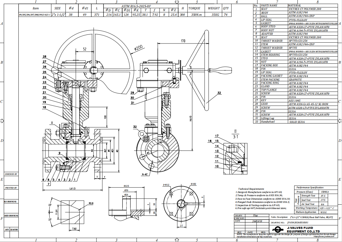
The stem passes through the body neck, and the packing sits in the body neck under a gland, inside the pressure boundary. What the extension does is move the gland nut, the lever and the operator away from the body, not the packing. The column above the body is a dry extension: a stem extension, a coupling that transmits the quarter turn, and a mounting plate at the top where the lever or the actuator sits. Because the packing stays where it was, the extension is not a pressure part, it does not change the rated pressure, and a leak at the gland will appear at the body neck rather than at the top of the column. The corollary matters for selection: an extension moves the operator out of the hot or cold zone, but it does not move the seal out of it. Where the requirement is to take the packing itself away from the temperature, what is needed is an extended bonnet with the packing at the top, which is a different component and a different drawing.
The anti-static path and the blowout retention belong to this design as well, even though they are often described only for trunnion valves. The stem is retained by the body so that it cannot be ejected by pressure, and a conductive path is fitted between ball, stem and body so that the assembly cannot accumulate a charge. Both are standard on this valve and both are stated on the data sheet rather than left to be assumed.
Material Options
The body is cast, not forged. The standard material is ASTM A351 CF8, the austenitic stainless casting equivalent to 304, with UNS number J92600. CF8M, the 316 equivalent, is available by order. The choice between them is a chloride question: CF8 is adequate for water, air, steam condensate and most neutral service, and CF8M is the correct choice where chlorides are present in the process, in a marine atmosphere or in a cleaning regime that leaves chloride behind. The boundary is not a number that can be written into a catalogue line, because chloride stress corrosion cracking depends on temperature, concentration and oxygen as much as on the chloride figure, so it is settled against the actual service conditions rather than against a table.
The ball is CF8 with hard chrome plating as standard, with a 316L ball available as an upgrade, and the stem is 316L. That combination is worth a note, because it is frequently mislabelled in enquiries. A valve with a CF8 body, a 316L ball and a 316L stem is not a 316 valve; the wetted body surface is still 304. Where the process needs 316 wetted parts, the body has to be CF8M and the order has to be placed as CF8M. Mixing the trim upward without moving the body is a way of paying for 316 and receiving 304 where it counts most.
The seats are PTFE, reinforced PTFE or PPL, and the packing is flexible graphite or PTFE. The seat compound is what sets the usable temperature of this valve, not the shell material and not the class. Each of these compounds has its own pressure temperature curve, and the curve has to come from the seat supplier for the compound actually fitted, at the class actually ordered. The figure printed for a metal seated variant of the same valve family does not transfer to a thermoplastic seat, and no soft seated valve of this size should be quoted against a figure that belongs to a metal seat.
The body gasket and the packing choice interact with the fire safe requirement. Where fire safe construction is specified, the certificate has to be issued against API 607 for this size, this class and this seat combination; a certificate held for another size or another seat does not cover the order. Where fire safe construction is not specified, the standard build is supplied and the data sheet says so.
| Component | Standard Material | Optional Upgrade | Service Notes |
|---|---|---|---|
| Body and end cap | ASTM A351 CF8 cast austenitic stainless, UNS J92600 | ASTM A351 CF8M for chloride service | Cast, not forged; the body is one pressure retaining joint with the end cap |
| Ball | CF8 with hard chrome plating | 316L ball | Bore through the ball is DN15 on a DN20 end size |
| Stem | 316L stainless steel | None offered | Retained by the body; conductive path fitted as standard |
| Seat rings | PTFE | RPTFE or PPL | The seat compound sets the usable temperature, not the class |
| Stem packing | Flexible graphite | PTFE | Located in the body neck, inside the pressure boundary |
| Body gasket | Non metallic sheet to the flange class | Graphite where fire safe construction is specified | Replaced whenever the end cap is opened |
| Extension column | 304 or 316 stainless, made to order | Length and top plate to the drawing | Dry column; packing remains in the body neck |
| Flange facing | ASME B16.5 raised face | RTJ where specified | Drilling follows the class, not the bore |
Technical Specifications
The table below carries the values that are fixed by the order and by the standards. It deliberately does not carry torque, flow coefficient, weight or the face to face dimension in millimetres, because none of those can be stated honestly for a valve that has not been built: they come from the signed general arrangement drawing for the size, the trim and the extension actually ordered. Where a buyer needs them for a calculation, they are issued with the drawing rather than quoted from a table that was written for a different configuration.
Two lines in the table need reading together. The pressure class is PN20, which is Class 150, and the ASME B16.34 rating for group 2.2 material at 38 C is 19.6 bar. The temperature range starts at -29 C, which is the low temperature limit for the carbon and low alloy parts in the assembly rather than a property of the stainless body, and the upper limit is not printed here because it belongs to the seat compound curve.
| Item | Value |
|---|---|
| Product type | Two piece side entry floating ball valve, reduced port |
| Nominal size | 3/4 in x 1/2 in, DN20 x DN15 |
| End size | Both flanges DN20; bore through the ball DN15 |
| Pressure class | PN20, equivalent to ASME Class 150 |
| Rating reference | ASME B16.34 group 2.2, 19.6 bar at 38 C |
| Body and end cap | ASTM A351 CF8; CF8M by order |
| Ball | CF8 with hard chrome plating; 316L by order |
| Stem | 316L |
| Seat | PTFE, RPTFE or PPL |
| Stem packing | Flexible graphite or PTFE |
| End connection | ASME B16.5 raised face flanged |
| Face to face | ASME B16.10, dimension on the signed drawing |
| Design standard | ASME B16.34 and API 608 |
| Test standard | API 598 |
| Extension | Dry column, length made to order |
| Operation | Lever, quarter turn, locking hole as an option |
| Actuation | Gear, pneumatic or electric on a top mounting plate |
Standards and Compliance
ASME B16.34 is the rating standard and it is the one that decides what the valve may be used for at temperature. API 608 is the product standard for flanged steel ball valves and it governs construction details such as stem retention and the requirements for the shell and seat tests. API 598 is the test standard and it is referenced by both. These three do different jobs and a data sheet that lists them as a single string without saying which does what is not much use to an inspector.
PN20 and Class 150 are the same class. API 6D lists PN20 against Class 150 in its pressure designation table, and with ASME B16.5 flanges the two callouts lead to the same flange drilling for the same nominal size. This is worth saying plainly because the reverse case exists in the trade: a PN number that no standard table contains is not a designation, it is a conversion, and a valve quoted against a converted number has no rating that an inspector can open a book and check. Where a PN designation appears on a drawing, it should be traceable to a table in API 6D or EN 1092-1.
The flange and face to face standards complete the chain. ASME B16.5 governs the flange dimensions, the facing and the bolt holes; ASME B16.10 governs the face to face dimension for the size and class. The face to face figure is a dimension, not a rating, and it belongs on the drawing. RM and RTJ facings are not interchangeable, and a raised face valve will not seal against an RTJ flange without the correct adapter.
Traceability runs on EN 10204 3.1. The heat number is cast or stamped on the body and the certificate for that heat is issued with the valve, so the material of the shell can be traced to the melt. Where a customer's specification calls for impact testing, hardness limits, a particular heat treatment condition or third party witness, those are order options and they are named on the certificate rather than assumed from the standard.
| Requirement | Standard | What J-VALVES Supplies |
|---|---|---|
| Pressure temperature rating | ASME B16.34 | Rating statement against group 2.2 at the ordered class |
| Product construction | API 608 | Valve built and marked to the standard, stem retention and anti-static path included |
| Shell test | API 598 | Test at 1.5 times the stated rating, held for the standard duration |
| Seat test | API 598 | Test at 1.1 times the stated rating, no visible leakage on a soft seat |
| Face to face | ASME B16.10 | Dimension confirmed on the signed general arrangement drawing |
| Flange dimensions | ASME B16.5 | Drilling, facing and thickness to the class |
| Material certificate | EN 10204 3.1 | Certificate for the body heat, matched to the marking on the casting |
| Fire safe construction | API 607 | Certificate naming the size, class and seat combination supplied, where specified |
| Marking | API 608 and the purchase order | Size, class, material, heat number and the customer tag where required |
Manufacturing Process
The body and the end cap start as castings. Each casting carries a heat number, and the heat is the unit of traceability from the foundry through to the certificate. Castings are cleaned, inspected for surface and sub surface defects, and the areas where the seat rings and the gasket sit are checked before any machining starts, because a defect in the seat pocket cannot be corrected by machining afterwards.
Machining is done in setups that keep the flange face, the gasket groove and the seat pocket concentric, since the seat ring has to sit square to the ball and the ball has to sit square to both seats. The ball is machined, ground and then chrome plated, and the plating thickness and adhesion are checked before the ball is accepted. The stem is machined from bar, and the sealing surfaces on it are finished to the surface condition the packing needs.
Assembly follows a fixed sequence: seats and ball into the main body, gasket onto the joint face, end cap on, studs torqued in a crossing pattern to the value on the process sheet. The extension is fabricated to the drawing and fitted after the body is assembled and tested, and the coupling is aligned so that the quarter turn is transmitted without side load on the stem. The top plate is set square to the stem axis, since an actuator bolted to a plate that is out of square will load the stem every time it strokes.

Quality Control and Testing
Every valve is shell tested and seat tested to API 598. The shell test is at 1.5 times the stated rating and it proves the body, the joint and the stem sealing under pressure. The seat test is at 1.1 times the stated rating and for a soft seated valve the acceptance is no visible leakage. Both are recorded against the serial number, and the record is what an inspector asks for when a valve is received on site.
Dimensional checks cover the flange drilling against ASME B16.5, the face to face against ASME B16.10 and the drawing, and the extension length against the approved drawing. Functional checks cover the quarter turn, the lever stop positions, the locking hole and, where an actuator plate is fitted, the alignment of the plate to the stem. Castings are examined visually and, where the purchase order asks for it, by a non destructive method named on the order.
Documentation is issued against the order and not against the catalogue. That means the material certificate carries the heat of the body actually supplied, the test report carries the pressures actually applied, and the drawing carries the extension length actually built. Where a certificate shows a different size or a different seat from the valve it accompanies, the certificate is not a substitute for the record, it is an error to be corrected before shipment.
| Step | What Is Checked | Standard or Acceptance |
|---|---|---|
| Incoming casting | Heat identification, surface condition, seat pocket integrity | Heat number recorded against the certificate |
| Ball and stem | Plating thickness and adhesion, sealing surface finish | Accepted against the drawing before assembly |
| Shell test | Body, joint and stem sealing at 1.5 times the rating | API 598, no leakage |
| Seat test | Seat tightness at 1.1 times the rating | API 598, no visible leakage on a soft seat |
| Dimensional | Flange drilling, face to face, extension length | ASME B16.5, ASME B16.10, approved drawing |
| Functional | Quarter turn, stop positions, locking hole, plate squareness | Operates through the full travel without binding |
| Marking and documentation | Size, class, material, heat number, tag | Matched to the purchase order before packing |

Applications and Industry Service
The core application is a traced or insulated small bore line, where the pipe is wrapped and the valve would otherwise be buried in the cladding with its lever inaccessible. Extending the stem brings the handle out through the insulation, which is cheaper and more reliable than cutting an access window into the lagging and hoping the operator puts it back. The same valve is used on buried runs where a pit or a short column brings the operator up to grade, and on low points under a rack where there is no room to swing a lever.
The second group is small bore utility service: instrument air branches, sample points, dosing and chemical feed lines, drain and vent connections on skids, and the isolation valves on analyser systems. In all of these the pipe is DN15 or DN20, the flow is small, and a reduced port valve is the correct economic choice because the pressure drop across the ball is not the constraint on the line.
Material selection follows the fluid rather than the application name. CF8 covers water, air, steam condensate and most neutral service. CF8M is chosen where chlorides are present, on marine and coastal installations, and in cleaning regimes that leave chloride on the wetted surfaces. Where the process is oxygen, the valve has to be degreased and the order has to say so; where the process is hydrogen or another small molecule, the packing choice becomes the governing item and graphite is normally the answer.
There are duties where this valve is the wrong choice and saying so saves a claim. It is not the valve for a line that has to be pigged, because the reduced port will not pass a pig. It is not the valve where pressure drop matters, because the port is one size down. It does not offer double block and bleed, because there is no cavity port to bleed from and no independent seat loading to make the double barrier meaningful. And it is not the valve for a gas tightness requirement at very low differential, for the reason set out above: the seat load comes from the pressure, and at a few tenths of a bar there is very little of it.
Installation, Operation and Maintenance
Install the valve with the stem vertical or horizontal, and leave room above the column for the lever to swing and for an operator to reach it. The column is not a structural member: it should not be used as a step, a support for the insulation, or a place to hang a tag line, and it should not be used to pull the pipe into alignment. Where the extension is long, support the column independently so that the weight and any side load do not end up on the stem and the packing.
Flange make up follows the gasket and the class. The bolts are tightened in a crossing pattern in stages, and the joint is checked for alignment before the studs are final. A raised face valve mated to an RTJ flange, or a gasket of the wrong type, will leak regardless of how carefully the studs are torqued, and neither is a valve fault.
Operation is a quarter turn, open or closed, with the lever against its stop at each end. The lever at the top of a long column gives the operator a good deal of leverage on the stem, and it should be used with that in mind: the column transmits the turning moment down a length of stem, so a lever that is forced past its stop or used to break something loose loads the coupling and the packing rather than the ball.
The seats and the ball can be reached without cutting the pipe, but not without isolating the line. The joint between body and end cap is a pressure retaining boundary and this body has no cavity port to vent, so the line is isolated, drained and proven before the studs are released. After that the end cap comes off along the pipe axis and the ball and both seat rings come out through the open end with the pipe flanges still made up. The body gasket and the cap studs are replaced on reassembly, and the valve is seat tested again before it goes back into service.
How to Specify and Order
An enquiry for this valve needs eight lines to be complete: the size and the bore, which means writing 3/4 in ends with a 1/2 in port rather than only 0.75 x 0.5; the class written as PN20 or Class 150, not both mixed with a converted number; the body material as CF8 or CF8M, not as 304 or 316 alone; the seat compound, because it sets the temperature; the flange facing and the standard, ASME B16.5 raised face unless something else is called for; the extension length and what it has to clear, which is the dimension most often left out; the operation, lever or actuator, with the actuator mounting details if an actuator is to be fitted later; and the documentation, meaning the material certificate, the test report and any third party witness.
With those eight lines the drawing can be issued without a round of questions. What comes back is a general arrangement drawing for the size and extension actually quoted, a material certificate for the body heat, a test report for the shell and seat tests, and, where fire safe construction is specified, a certificate naming the size, class and seat it covers.
The item that most often goes wrong is the extension. A length quoted without the thickness of the insulation, the depth of the pit or the height of the operating level is a guess, and a column that is too short ends up inside the cladding while one that is too long puts a bending load on the stem every time the lever is pulled. The dimension should be taken from the installation, written on the enquiry, and confirmed on the drawing before the valve is built.
FAQ
Q: Is PN20 the same as Class 150?
A: Yes, they are two names for one class. API 6D lists PN20 against Class 150 in its pressure designation table, and with ASME B16.5 flanges the two callouts lead to the same drilling for the same nominal size. What they are not is interchangeable with a PN number that no table contains: a converted figure is not a designation, and a valve quoted against one has no rating an inspector can look up. ASME B16.34 rates group 2.2 material, which includes CF8, at 19.6 bar at 38 C for this class.
Q: The valve is called 3/4 x 1/2 in. Are the two flanges different sizes?
A: No. Both flanges are three quarter inch, DN20, and the 1/2 in is the bore through the ball, which is DN15. It is a reduced port valve, not a reducing valve, and the distinction decides the application: the line it bolts to is DN20 and the flow path inside it is one size smaller. The pressure class belongs to the shell, so a reduced port body is rated exactly as a full port body of the same class and material. Where the two ends really are different sizes, that is a reducing valve and it is ordered as one.
Q: Does the extended stem change the pressure rating, or move the packing out of the hot zone?
A: Neither. The packing stays in the body neck under a gland, inside the pressure boundary, and the column above the body is a dry extension: a stem extension, a coupling and a top plate. So the rated pressure is unchanged, and the seal is still at body temperature. What the extension moves is the operator, and that is what it is for on insulated, traced, buried or low level installations. Where the requirement is to take the packing itself away from the temperature, an extended bonnet with the packing at the top is the component that does it, and that is a different drawing.
Q: Why does a floating ball valve weep at low pressure and seal at high pressure?
A: Because the seat load is the pressure. There are no trunnions holding the ball, so line pressure pushes the ball into the downstream seat and the sealing force is that pressure acting on the seat annulus. At a differential of a few tenths of a bar there is almost nothing to push with, and sealing depends on the resilience left in the seat ring. This is the design working as designed, and it is the reason a gas tightness requirement has to be written into the enquiry instead of being inferred from the pressure class.
Q: Can the seats be changed without cutting the pipe?
A: Yes, but not without isolating the line. The joint between body and end cap is a pressure retaining boundary held by studs, and this body has no cavity port to vent, so the line is isolated, drained and proven first. After that the end cap comes off along the pipe axis and the ball and both seat rings come out through the open end with the pipe flanges still made up. The body gasket and the cap studs are replaced on reassembly and the valve is seat tested again.
Q: When should this be a trunnion mounted valve, or a three piece valve, instead?
A: A trunnion valve when the duty needs double block and bleed, double piston effect seats, a double barrier, or a torque that a lever cannot reasonably handle, because none of those exist on a floating ball. A three piece valve when the middle section has to be changed out without disturbing the pipe, which is a real advantage at larger sizes and rarely worth the second pressure joint at DN20. The two piece body here has one joint, one gasket and one set of studs.


Hot Products


News
Ball Valves in A Kraft Pulp Mill: Black Liquor, Green Liquor And The Cost of Choosing The Alloy by Habit
White liquor at pH 14 cracks carbon steel welds, black liquor sets solid below 100 C, green liquor dregs grind seats: alloy choice and torque in a kraft mill.
Read More
Slug Flow And Ball Valves: What Actually Arrives At The Seat
A slug is liquid mass with momentum, not a pressure spike. What changes at the seat, in the cavity and at the actuator when liquid reaches a ball valve.
Read More
Ball Valves in Direct Lithium Extraction: PH 1 Eluate, Gypsum Scale And 438,000 Cycles in Twenty-Five Years
Direct lithium extraction swings valves from pH 1 eluate to pH 12 caustic, 48 column switches a day and gypsum scale. Materials, seats and torque.
Read More
Ball Valves in Geothermal Brine: Silica Scale, Chloride Cracking And The Cooling Trap
Why geothermal brine destroys ball valves: retrograde silica scale, calcite at the flash point, chloride cracking above 60 C and the 250 C seat limit.
Read More