


CHINA J-VALVES Offers Various High-quality I ndustrial Ball Valves
J-VALVES, a distinguished professional ball valve manufacturer rooted in China, takes pride in its extensive product portfolio. Our offerings span a wide range, including trunnion-mounted ball valves, floating ball valves, high-temperature ball valves, high-pressure ball valves, metal-sealed ball valves, ultra-low temperature ball valves, DBB ball valves, Three-way And Four-way Ball Valve, and fully welded ball valves. Each product is a testament to our commitment to precision engineering and reliable performance. Meticulously crafted, they are designed to not only meet but exceed the most stringent industrial demands, ensuring stable operation even under extreme conditions. This enables us to provide our clients with high-value services and makes our valves widely sought-after in industries.
Product Category
Contact Us


-
J-VALVES-Q41F
-
J-VALVES
Overview of the J-VALVES DN80x50 Class 1500 F44 Floating Ball Valve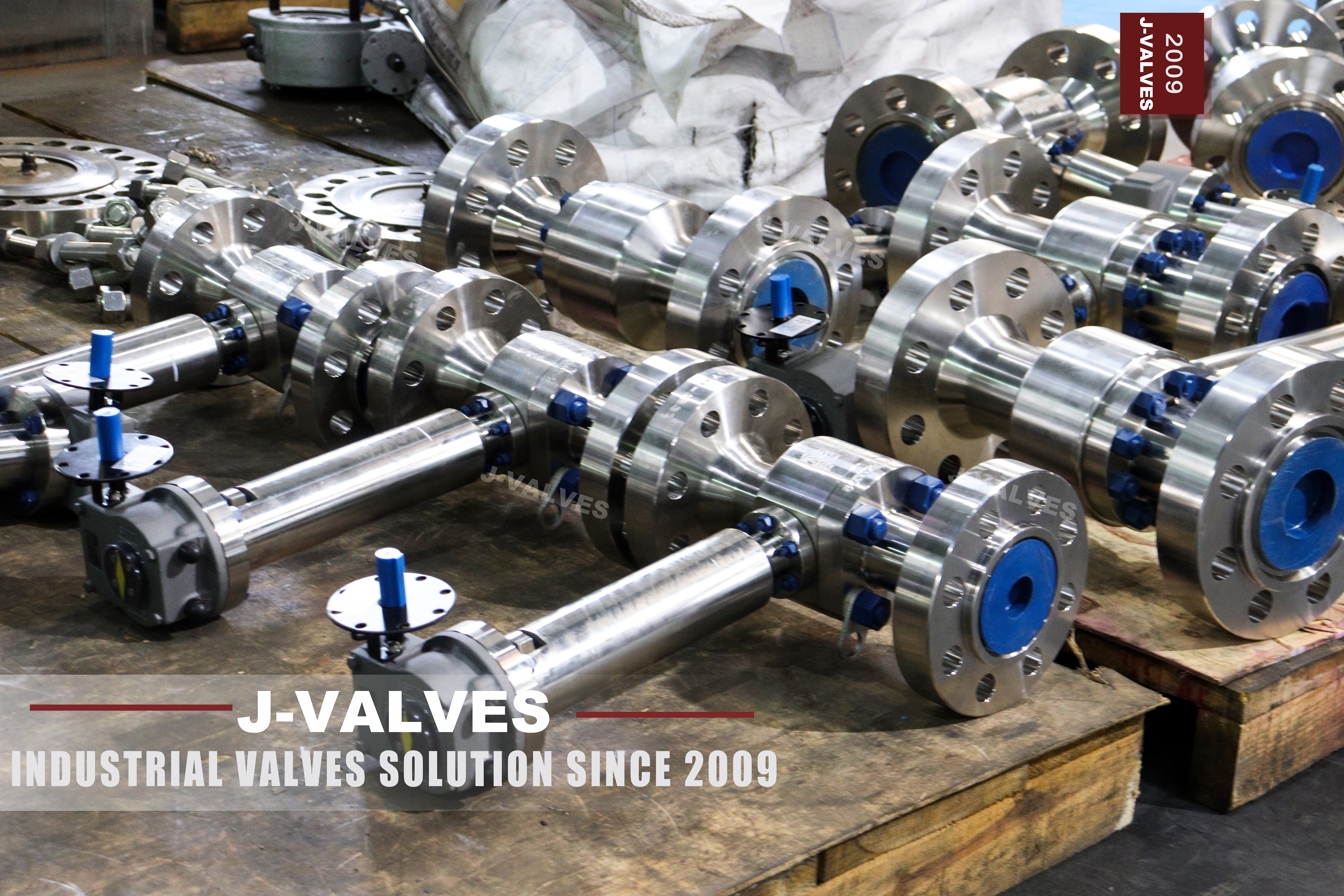
This is a two piece flanged floating ball valve on a DN80 body with a DN50 bore, rated Class 1500, forged in ASTM A182 F44, ending in ring joint flanges, and fitted with a bolted stem column that carries a worm gearbox at the top. Four lines are stamped on the body barrel: DN80x50, 1500, F44 and the heat number CF250327-2. The same heat number is stamped vertically on the end cap, which is the only way to show that the two halves of a two piece body came from one heat of steel.
The middle of this valve is a solved problem. A two piece forged body, a floating ball, a polymer seat and an extended column are ordinary work for a valve shop, and nothing in the middle is where a project loses money. The losses sit at three interfaces, and no standard describes any of them completely. The first is the flange: a ring joint is a family of three ring forms rather than one facing, and the letter that decides which form was machined is not on the nameplate. The second is the column: nothing fixes where an extension length is measured from, so the same figure on two quotations can be two different valves. The third is the insulation, which covers the parts that have to be reached. The ten sections below are arranged around those three.
What the valve is not is worth settling first. It is not a trunnion valve, so the ball rides on the seats rather than on bearings. It has no double block and bleed in the trunnion sense, because a floating ball seals on one seat at a time. The reduced bore rules it out of any line that will ever be pigged. And the alloy has an edge: F44 resists chloride pitting and crevice attack far better than 316, but it is not a nickel alloy, so hot concentrated chloride or wet chlorine gas is a different product. Above Class 1500, or well above this bore, the enquiry belongs with a trunnion valve.
Design and Construction
The body is two pieces: a main forging that carries both pipe flanges, and one end cap that closes the cavity from the pipe side. That single gasketed joint is a pressure boundary at this class, and it is the joint that opens when the seats are changed, which is why the halves are stamped with the same heat number and why the gasket is a purchased item with a grade on it rather than something taken from a bin.
The stem leaves the body through a bolted cover rather than through the barrel. That cover is a pressure joint in its own right, and on this valve it sits at the bottom of the column, which makes it the joint nobody wants to disturb: opening it means taking the gearbox and the column off first, and the line has to be isolated and drained before either can move.
The ball floats. Nothing holds it except the two seats, so pressure on the closed bore area pushes it downstream and the whole load lands on the downstream seat, which has to contain that load through a polymer without letting the polymer extrude out of its pocket. This is why the bore matters more than the body size: the seat sees a DN50 circle while the flanges belong to a three inch valve. At Class 1500 that difference is the reason this is a floating design at all, and it is also the reason a soft seat here needs a tight pocket and an anti-extrusion ring rather than a plain one.
The column in the photograph is a plain tube, bolted to the cover at the bottom and flanged for the gearbox at the top, with no window in it. Two things follow. The coupling that joins the valve stem to the extension shaft is inside the tube and cannot be seen, so that joint is verified by the drawing and by the torque record rather than by looking at it. And the packing has not moved: it stays in the body cover at line temperature, and the tube above it is dry. Where a window is provided the coupling can be inspected in place; on this build it cannot, and the gearbox has to come off before anything above the cover is touched.
A column is also a lever. The gearbox sits at the top of it, and a handwheel is pushed sideways as much as it is turned, so the column base carries a bending moment that the cover studs have to hold. Those studs are sized for the moment, not only for pressure, which is why the base of the column is the place to look after a valve has been operated by someone leaning on the wheel.
The operator is a right angle worm gear with a handwheel on a horizontal input shaft. On a valve this size the gear is not there for torque; a DN50 bore at Class 1500 is within reach of a lever. It is there because the operator stands at the top of a column, where a lever would need a clear quarter circle of space at head height and would put a hand above the lagging instead of beside it. The cost is feel: a gearbox hides the seat, so the valve can be forced against its stop without the hand noticing.
Inside, the stem has a shoulder trapped by the body, so pressure cannot blow it out, and a conductive path keeps ball, stem and body electrically continuous. Fire safety is not a certificate but a set of parts that survive a fire: graphite packing, a graphite filled body gasket, and the metal shoulder behind each seat that the ball can still land on after the polymer has burned.
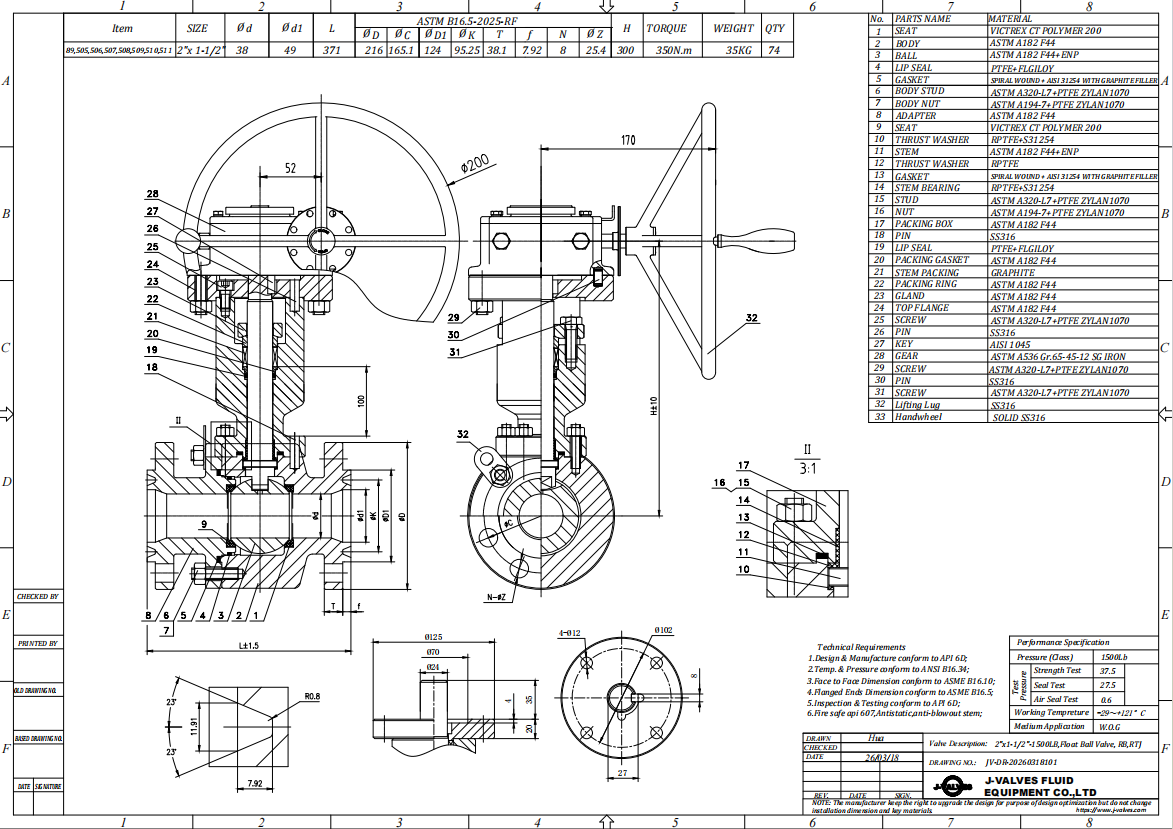
Material Options
F44 is a forging grade and the order has two correct names for it: ASTM A182 F44 and UNS S31254. The other names in circulation are a mill's trade name and a family nickname for the six percent molybdenum alloys, and neither belongs on a purchase order, because a certificate never comes back using them. The body is forged rather than cast for a reason that is about thickness: at this class the section is heavy and the bore is small, so a shrinkage cavity that would be a note on a casting drawing sits inside a pressure boundary here.
What the price buys is the molybdenum. About twenty percent chromium forms the passive film, roughly eighteen percent nickel holds the austenitic structure, and six percent molybdenum is what resists pitting and crevice attack in chloride. Nitrogen adds strength and pitting resistance, copper is there for sulphuric acid, and carbon is held at or below 0.02 percent, which is why there is no low carbon variant of this grade to order.
What it does not buy matters more. The alloy resists crevice attack; it does not abolish crevices. A 6Mo valve in chloride service fails where the geometry makes a crevice, and this valve has four: behind the seat ring in its pocket, in the recess that holds the body joint gasket, under the thread of the cavity drain plug, and between the ball and the seat while the valve is shut. Three of the four are answered by design, with a tight pocket, a gasket that fills its recess and a plug in the same alloy. The fourth is the service itself, because a closed valve on stagnant chloride is a stagnant crevice by definition.
The alloy also does not replace a nickel alloy and does not raise the pressure class. Its allowable stress sits below carbon steel in the same class, so an F44 body at Class 1500 is thicker and heavier than the same body in WCB, not lighter. Anyone buying 6Mo is buying corrosion resistance and paying for it in wall thickness. The grade is also a forging grade in the strict sense: offered as a casting, the certificate changes to A351 CK3MCuN, and a buyer who specified A182 F44 has not specified a casting.
Ball and stem are the two parts nobody photographs. The ball is offered in F44 with hard chrome or with nitriding, both surface treatments on the same base metal, and the choice is about wear in dirty service rather than about corrosion. The stem is offered in F44 or 17-4PH: 17-4PH is much stronger and markedly less resistant to chloride stress corrosion, so an F44 body with a 17-4PH stem puts the weaker alloy where no photograph reaches. Because the column on this build is closed, neither part can be inspected in place, so both are verified on the certificate rather than on the valve.
Seats and packing are where class and temperature meet. PTFE, RPTFE, PEEK and PPL each have their own ceiling, and one range printed across all four describes none of them. At Class 1500 differential the polymer also has to be restrained, because a soft seat that is allowed to flow loses its contact pressure permanently and does not recover when the pressure comes off. Packing works the other way round: graphite is what survives a fire, PTFE seals to a lower leakage rate and is the first thing to fail.
The last material decision is the one most often left to the supplier: bolting and the small fittings. A carbon steel stud or a carbon steel drain plug in a 6Mo body is a galvanic couple, and the small part is the one that corrodes. Either controlled alloy steel with a proper coating or a matching stainless, and either way the certificate should say which.
| Component | Standard Material | Optional Upgrade | Service Notes |
|---|---|---|---|
| Body and end cap | ASTM A182 F44 forging, UNS S31254 | A182 F316 where chloride is low | Both halves carry the same heat number |
| Ball | A182 F44, hard chrome plated or nitrided | Cobalt alloy overlay on request | Not a pressure part, grade on the certificate |
| Seats | PTFE, RPTFE, PEEK or PPL | Metal ring with hardfacing | The seat, not the body, caps the temperature |
| Seat pocket | Tight clearance plus anti-extrusion ring | Metal seated pocket for high differential | A flowing seat loses its load permanently |
| Stem | A182 F44 | 17-4PH for higher strength | 17-4PH is the weaker alloy in chloride |
| Stem packing | Flexible graphite | PTFE for low emission duty | Graphite is the fire safe path |
| Body gasket | Spiral wound, graphite filler | PTFE filler for clean duty | New gasket at every joint opening |
| Cover studs | Alloy steel with coating | Matching stainless | Sized for the handwheel moment, not just pressure |
| Cavity plug | A182 F44 | Matching alloy | Same alloy as the body, reachable after lagging |
Technical Specifications
The class has four numbers in circulation and only one of them is on the valve. The metal says 1500. API 6D clause 7.2 records this class as PN 250, and EN 1092-1 has a PN 250 grade of its own, so the European name exists but names a different flange. The sheet offers PN 260, which appears in neither list, and looks like the rating converted into bar and rounded; a converted number is not a designation. None of the four is the rating itself, which is a table value taken from the material group in ASME B16.34 and which falls as the temperature rises.
The ends are the first place where a drawing has to be read rather than a catalogue. NPS 3 at Class 1500 is a ring joint flange, and the groove is machined to a profile identified by a ring number rather than by the words ring type joint. Two valves can both be described as RTJ and still take different rings, and the valve ships with the groove and without the ring, so the letter is a purchasing decision that has to be made before the valve is built, not after it arrives.
The bore is DN50 inside a DN80 body. The second number is not a derating: the shell and the ends are rated at Class 1500 and the bore only changes what the seats and the ball see. What it does change is permanent. There is no kit that turns this into a full bore valve, because that means a different ball, different seats and a different end cap, and a pig sized to the line will not pass through it.
Temperature takes two rows and the lower one governs. The body row comes from the austenitic group in ASME B16.34, whose flange rating is listed to 1000 F. The seat row is much shorter: PTFE to about 200 C, PEEK to about 260 C, PPL close to PEEK. The 425 C that appears on the original sheet is a carbon steel habit rather than a figure this alloy and this seat can both hold, and at 1500 differential the seat is the part that fails first in every case.
| Item | Value |
|---|---|
| Size | DN80 ends by DN50 bore, NPS 3 by NPS 2 |
| Pressure class | Class 1500, recorded as PN 250 in API 6D clause 7.2 |
| Rating at 100 F | 3600 psi, ASME B16.34 austenitic group |
| Body material | ASTM A182 F44, UNS S31254 |
| End connection | Ring joint flange, ASME B16.5, Class 1500, NPS 3 |
| Ring groove | Machined to the ring number on the GA drawing |
| Bore | DN50, reduced, not convertible to full bore |
| Face to face | ASME B16.10 table value and the signed GA drawing |
| Temperature, body | Flange rating listed to 1000 F |
| Temperature, seat | About 200 C for PTFE, about 260 C for PEEK |
| Stem packing | Flexible graphite |
| Design standard | API 608 with ASME B16.34 |
| Test standard | API 598, shell and seat |
| Extension | Column height and operator position fixed on the GA drawing |
Standards and Compliance
Five documents share this valve and each owns a different part of it. ASME B16.34 sets the wall thickness and the pressure temperature rating. ASME B16.5 sets the flange, including the ring joint facing and the groove that is machined into it. ASME B16.20 sets the ring that sits in that groove. API 608 is the product standard for floating ball valves, and it is where the requirements that belong to the valve rather than to its ends come from: anti static continuity, anti blowout stem, fire performance. API 598 sets the test.
The orphan in that list is the ring. It is the only part of the joint that neither flange standard buys for you: B16.5 dimensions the groove in the valve, B16.20 dimensions the ring, and the two are matched by a ring number which appears on neither the nameplate nor the delivery note. So the valve arrives with a groove and no ring, and the site is expected to fit the correct one. That is a small part to be the difference between a joint that seals and a joint that weeps, and it is the part most often ordered from memory.
Ring type joint is a family of three, not a facing. The R ring comes in oval and octagonal section and both fit the same groove, which is the single interchangeability in the family. The RX ring does not: it is a pressure energised ring with a groove of its own, and an RX groove will not accept an R ring nor the reverse. BX is a third form that belongs to wellhead flanges under API 6A and has no place on a B16.5 valve at this class. An order that says RTJ has therefore specified a category and left the decision open.
Test pressures are fixed and acceptance is not. API 598 gives the shell test at 1.5 times the rating and the seat test at 1.1 times, and then leaves the acceptance to the seat type: a polymer seat is expected to show no visible leakage, while a metal seat is accepted at a rate by size. So the standard number on a data sheet does not state a tightness, and an order that asks for both a polymer seat and a metal seat rate has asked for two different valves.
The last group is conditional. Fire performance to API 607 or ISO 10497 is a type test, and its certificate covers a range of sizes and classes rather than one valve, so read what the certificate covers instead of the logo on the cover. NACE MR0175 enters only if the service is sour, and then it caps 17-4PH hardness, which is where the strongest stem option stops being available. Marking follows API 608 and should carry the size, the class, the material and the heat number that are already on the body.
| Requirement | Standard | What J-VALVES Supplies |
|---|---|---|
| Pressure and temperature rating | ASME B16.34, austenitic group | 3600 psi at 100 F, falling with temperature |
| Flange and facing | ASME B16.5 Class 1500, NPS 3 | Ring joint facing, groove per the drawing |
| Ring groove and ring | ASME B16.5 groove, ASME B16.20 ring | Groove machined and checked, ring quoted separately |
| Product standard | API 608, named on the order | Floating ball scope, anti static, anti blowout |
| Shell test | API 598 | 1.5 times the rating, no leakage |
| Seat test | API 598 | 1.1 times the rating, zero visible on polymer |
| Fire performance | API 607 or ISO 10497 | Certificate stating the sizes and classes covered |
| Sour service | NACE MR0175 when declared | Hardness limits applied and reported |
| Marking and paperwork | API 608 marking | Stamp, nameplate, EN 10204 3.1 file |
Manufacturing Process
A DN80 Class 1500 body in F44 starts as a forged billet rather than a casting. At this class the wall is heavy and the bore is small, so the section between the cavity and the outside is thick, and that is where a forging earns its price: it closes the porosity that a thick cast section can hide, in a place where nothing can be inspected from outside afterwards.
The ends carry most of the metal and they are finished last. The ring groove is cut to the profile of the ring number on the drawing, the flange face is finished after the groove so that the facing is not disturbed by a second operation, and both are protected from that point to the crate. A scored or out of round groove cannot be corrected on a forged 6Mo flange without welding and remachining, and welding a pressure flange at the end of a build is a decision nobody wants to take.
Assembly is where the clearances that never appear on a drawing are set. The seat pocket is checked before the seats go in, the anti-extrusion ring goes behind the seat, the ball is left free to float but centred on the bore, the cover studs are torqued in a cross pattern in stages, and the cavity plug goes in last so that the drain path is not blocked by thread sealant.
Then the valve is tested, drained and dried, the ends are capped, and the body is stamped. The stamp is four lines and it is the whole material record that travels with the valve: size, class, grade and heat number. Everything else, including the bore and the groove, is in the paperwork rather than on the metal.

Quality Control and Testing
The inspection that matters most here is the one easiest to skip, and it is the groove. A groove that is out of round, scored or cut to a neighbouring profile passes a visual check and then leaks at the joint, because a ring joint does not seal by compression. It seals by the ring being confined between the groove walls, so a groove one profile away from the ring will not seal whatever the bolt load, and the leak appears only when the line is pressurised for the first time.
The second is identification. The flange is what people see and the bore is what the order was about, so a valve whose ends measure three inch and whose port measures two inch will be filed as a three inch valve by anyone reading the flange alone. The bore is therefore measured and recorded against the stamp, and the paperwork carries DN80x50 rather than a rounded size.
Certificates are the third. The 3.1 file has to carry heat numbers that match the stamps, and the ball and stem are named on it because neither can be seen once the valve is assembled. Positive material identification is useful on this alloy, because molybdenum reads clearly on a portable gun and separates the six percent grade from a 316 that was substituted; carbon does not read, so the carbon content stays on the paper rather than in the reading. The ring, when supplied, comes with its own certificate and its own ring number, and that number is checked against the groove before the flange is closed.
| Step | What Is Checked | Standard or Acceptance |
|---|---|---|
| Incoming material | Heat number, certificate, grade | EN 10204 3.1 matching the stamps |
| Rough machining | Wall, bore path, seat pocket | General arrangement drawing |
| Groove machining | Profile, concentricity, surface | Ring number on the drawing, ring trial fit |
| Seat and ball fit | Pocket clearance, anti-extrusion ring, float | Drawing, ball free and centred |
| Assembly torque | Cover studs, body joint studs | Cross pattern, staged, recorded |
| Shell test | Body, joints, stem sealing | API 598, 1.5 times, no leakage |
| Seat test | Both seats, both directions | API 598, 1.1 times, zero visible |
| Continuity | Ball to stem to body | Ten ohms or less, test point recorded |
| Marking and paperwork | Stamp, nameplate, bore record, PMI | API 608 marking, file complete |

Applications and Industry Service
The pairing that produces this valve is chloride plus pressure. Seawater injection, produced water, hypochlorite dosing, and acid lines concentrated enough that 316 is not sufficient and not concentrated enough to need a nickel alloy. In all of them the pressure comes from a pump upstream and the chloride comes from the medium, and in most of them the valve is shut for far longer than it is open, which is the worst duty a stainless seat pocket can be given.
That last point deserves its own paragraph, because it is the one the datasheet never mentions. A valve that is closed for a season holds a pocket of liquid with no flow through it, at line temperature, against two seats. Chloride concentrates in the crevices while the oxygen that keeps the passive film intact is consumed, and the attack starts where nobody is looking. The answer is not a better alloy but a procedure: flush or drain the cavity when the valve is shut for a long period, and work the valve occasionally so that the seat does not sit in one position for a year.
Where this valve does not belong is worth stating as plainly as where it does. Any line that will be pigged is out, because the bore is reduced and the pig is sized to the pipe. Any scheme that needs double block and bleed is out, because a floating ball gives one seal at a time. Hot concentrated chloride and wet chlorine gas are out, because those are nickel alloy duties and a 6Mo body would be the wrong purchase. And above Class 1500, or well above this bore, the answer is a trunnion valve.
Installation, Operation and Maintenance
A ring joint is a one attempt joint, and the attempt is made during assembly rather than during commissioning. The groove is cleaned and inspected, the ring is checked for its number and for damage, the ring goes in dry because a lubricated ring can shift under load, the studs are lubricated on the thread and under the nut, and the joint is made up in a cross pattern in stages. What must not happen afterwards is chasing a weep by tightening: a ring joint that weeps is usually a damaged ring or a wrong groove, and adding load yields the flange, and the groove lives in the valve body.
Installation decides whether the valve can be maintained. The column has to stand vertical, because a column is a lever and an inclined one bends the stem and loads the packing on one side. The gearbox needs a height where a person can stand and turn the wheel with both hands, and the wheel needs clearance for its rim rather than for its centre. The drain plug, the stamp and the cover studs all have to survive the cladding, and that is a layout decision taken before the insulation gang arrives, not after.
A leak on this joint looks different from a leak on a gasket. The seal sits inside the bolt circle, so what escapes leaves at the outside diameter of the flanges, between the studs, and on a lagged line that path is behind the cladding. The first evidence is staining in the insulation or corrosion on the studs, not a drip on the floor, which is why a lagged ring joint deserves a visible check at the flange outside diameter at every shutdown.
Servicing follows the structure. The packing is in the body cover, under the column, so a packing job begins with the gearbox and then the column, and it is a lifting job at height rather than a gland nut turned in place. The seats and the ball come out through the end cap, which means the line is isolated, drained and the joint broken, and the gasket is replaced rather than reused. And when the valve will not turn, the answer is not a bar on the handwheel: the usual cause is thermal, with liquid trapped in the cavity expanding as the line heats, and the cavity plug exists for exactly that.
How to Specify and Order
Four lines in the order decide whether this valve fits, and no standard will write any of them for you. The first is the ring: the facing form, the ring number, and whether the rings are in the valve order or already on site. The second is the extension: the dimension, the datum it is measured from, the outside diameter of the cladding and the clearance the wheel needs above it. A figure without a datum is not a dimension, and two suppliers quoting the same number from different datums will deliver valves that differ by the height of the body.
The third line names the wet parts rather than describing them: ball, seats, packing, body gasket and the small fittings, each by grade. The fourth names the paperwork: a 3.1 certificate with heat numbers matching the stamps, a positive material identification report, the ring certificates with their numbers, the shell and seat records with the values written down, and a general arrangement drawing for approval before machining starts.
A specification that gets this valve right reads: two piece flanged floating ball valve, DN80 by DN50 reduced bore, Class 1500, body and end cap to ASTM A182 F44 (UNS S31254), ball in the same grade with hard chrome, seats in PEEK, stem in A182 F44, graphite packing, ring joint flanges to ASME B16.5 NPS 3 with the groove for the ring number stated, extended stem column of the stated height measured from the stated datum with a worm gear operator, design to API 608 and ASME B16.34, tested to API 598, EN 10204 3.1 with heat numbers, PMI report, and a general arrangement drawing for approval.
At enquiry, send the medium with its chloride level and its temperature, the class, the mating flange standard and the groove already in use on the line, the insulation thickness and the height at which the operator will stand, and whether the line will ever be pigged. Those six answers settle the alloy, the seat, the groove and the column, and they settle them before a quotation is written rather than after a valve is delivered.
FAQ
Q: Which ring groove will this valve have, and can it be changed after delivery?
A: Only the drawing knows, and that is the problem. A ring joint flange can be machined with an R groove or an RX groove, the two do not accept the same ring, and the letter has to be in the order before the body is machined. After delivery the groove is a feature of a forged 6Mo flange: changing it means welding and remachining a pressure flange, which nobody should plan. Send the ring number already used on the line, or send the ring itself, and have the drawing state the groove before machining starts.
Q: Why does a valve with a DN50 bore need a gearbox?
A: It does not need one for torque. A DN50 bore at Class 1500 is inside the range where a lever would do the job, and a lever is what the original sheet offers. The gear is there because the operator stands at the top of a column: a lever at that height needs a clear quarter circle of free space and puts a hand above the insulation instead of beside it. The price is feel, because a worm gear hides the seat and the valve can be forced against its travel stop without the hand noticing.
Q: Can the packing be renewed with the line still under pressure?
A: No. The packing sits in the body cover below the column, and that cover is a gasketed pressure joint, so the work starts with the gearbox, then the column, then the gland. On a column with a window the gland can at least be reached and adjusted; on this closed tube it cannot even be seen. What is possible in service is limited to what does not cross the pressure boundary. Isolate, vent the cavity through the drain plug, and then work from above.
Q: Once the line is lagged, what can no longer be reached?
A: Four things, and all of them matter. The ring joint itself, whose leak path leaves at the flange outside diameter between the studs; the cavity drain plug; the body stamp with the heat number; and the cover studs at the base of the column. On an insulated line all four sit inside the cladding. Decide at layout whether the drain is extended through it, whether a hatch is left at each flange, and whether the stamp is repeated on a tag fixed outside.


Hot Products


News
Ball Valves in A Kraft Pulp Mill: Black Liquor, Green Liquor And The Cost of Choosing The Alloy by Habit
White liquor at pH 14 cracks carbon steel welds, black liquor sets solid below 100 C, green liquor dregs grind seats: alloy choice and torque in a kraft mill.
Read More
Slug Flow And Ball Valves: What Actually Arrives At The Seat
A slug is liquid mass with momentum, not a pressure spike. What changes at the seat, in the cavity and at the actuator when liquid reaches a ball valve.
Read More
Ball Valves in Direct Lithium Extraction: PH 1 Eluate, Gypsum Scale And 438,000 Cycles in Twenty-Five Years
Direct lithium extraction swings valves from pH 1 eluate to pH 12 caustic, 48 column switches a day and gypsum scale. Materials, seats and torque.
Read More
Ball Valves in Geothermal Brine: Silica Scale, Chloride Cracking And The Cooling Trap
Why geothermal brine destroys ball valves: retrograde silica scale, calcite at the flash point, chloride cracking above 60 C and the 250 C seat limit.
Read More