


CHINA J-VALVES Offers Various High-quality I ndustrial Ball Valves
J-VALVES, a distinguished professional ball valve manufacturer rooted in China, takes pride in its extensive product portfolio. Our offerings span a wide range, including trunnion-mounted ball valves, floating ball valves, high-temperature ball valves, high-pressure ball valves, metal-sealed ball valves, ultra-low temperature ball valves, DBB ball valves, Three-way And Four-way Ball Valve, and fully welded ball valves. Each product is a testament to our commitment to precision engineering and reliable performance. Meticulously crafted, they are designed to not only meet but exceed the most stringent industrial demands, ensuring stable operation even under extreme conditions. This enables us to provide our clients with high-value services and makes our valves widely sought-after in industries.
Product Category
Contact Us


Pressure Class: 10K (1.0MPa)
Temperature Range: -29℃ to +425℃
Body / Bonnet: Cast stainless steel ASTM A351 CF8 (equivalent to 304)
Ball: CF8 / 304 with hard chrome plating, or 316 stainless steel (optional)
Stem: 304 or 316 stainless steel
Seat: PTFE, RPTFE, PPL (reinforced PTFE)
Sealing Materials: PTFE / RPTFE / PPL (seat), flexible graphite or PTFE (stem packing)
End Connection: Japanese standard flanged (RF Raised Face, conforming to JIS B2220)
Operation: Lever (90° open/close, optional locking hole), worm gear, pneumatic, electric (optional)
Design Standards: JIS B2071, ASME B16.34, API 608
Testing Standards: API 598, JIS B2003
Face-to-Face Dimension: Conforms to JIS B2002
-
J-VALVES-Q41F
-
J-VALVES
150A 10K CF8 Two Piece Stainless Steel Floating Ball Valve: What the Designation Fixes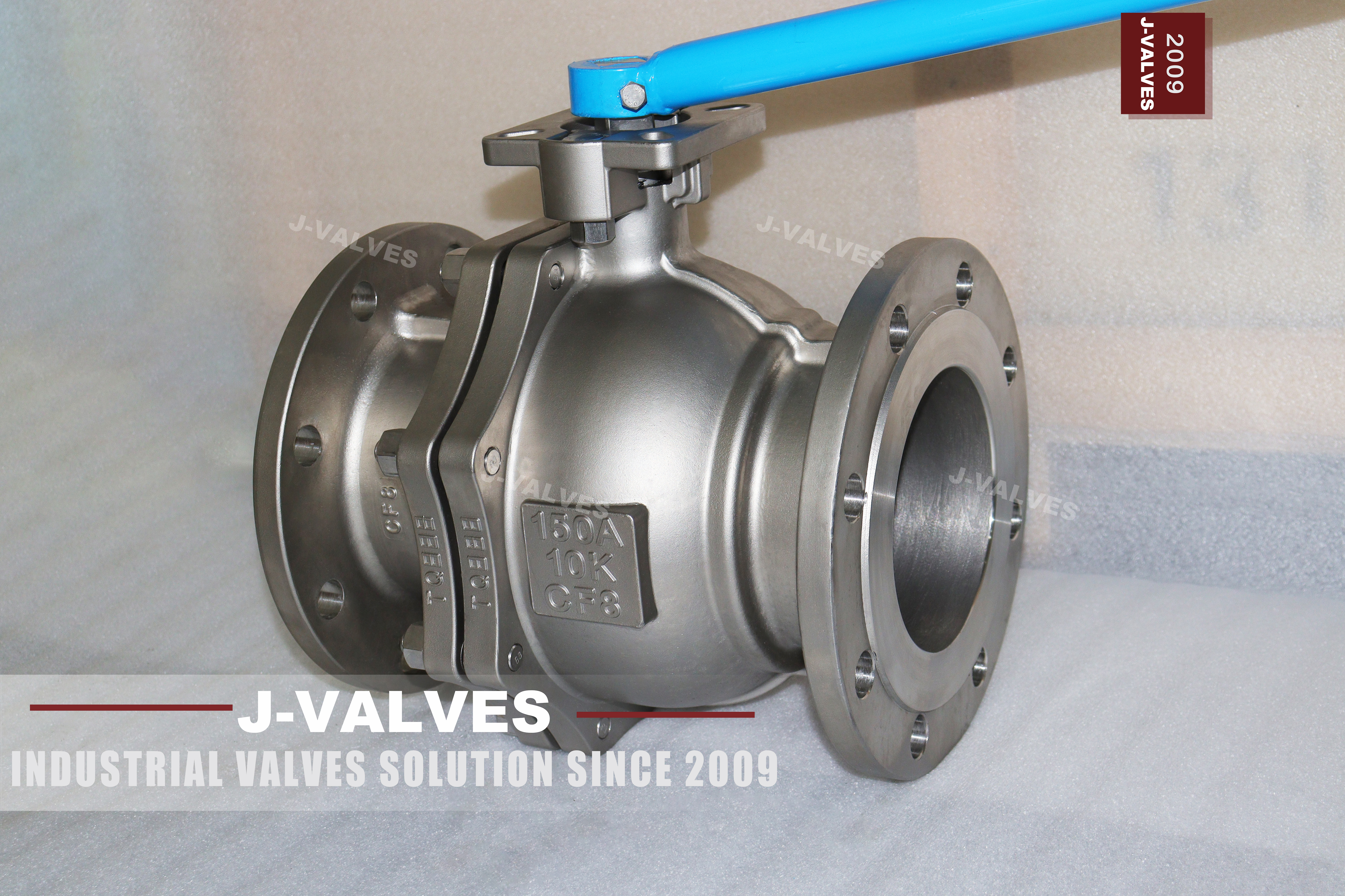
A JIS ball valve is specified by three separate things: the nominal size callout, the JIS pressure classification, and the pipe flange standard that joins the valve to the line. On this valve they are 150A, 10K and JIS B2220. None of the three converts into an ASME designation on its own, and the assumption that they do is where most of the trouble on this size begins.
The valve is a two piece side entry floating ball valve in ASTM A351 CF8 cast stainless steel, full bore, soft seated, with a lever as standard. It is bought for water, weak chemical, food and pharmaceutical duty on lines that were designed to Japanese standards rather than to ASME ones, which is the case across a large part of the plant and marine work in East and Southeast Asia.
| Parameter | Value |
|---|---|
| Product type | Two piece side entry floating ball valve, full bore |
| Nominal size | 150A, DN150, 6 inch nominal |
| Pressure classification | JIS 10K, nominal 1.0 MPa |
| Body material | ASTM A351 CF8 cast austenitic stainless, UNS J92600 |
| Ball | CF8 with hard chrome plating, 316 stainless optional |
| Stem | 304 or 316 stainless steel |
| Seat | PTFE, RPTFE or PPL |
| Stem packing | Flexible graphite or PTFE |
| End connection | JIS B2220 10K raised face flanged |
| Face to face | JIS B2002 |
| Design standard | JIS B2071, with API 608 and ASME B16.34 as reference |
| Test standard | API 598 and JIS B2003 |
| Fire safe | API 607 |
| Operation | Lever, 90 degree travel, locking hole as an option |
150A Means DN150, and 10K Means 1.0 MPa, Not 150 psi
The A in 150A is the Japanese nominal size series that is dimensioned in millimetres. 150A is the 150 mm nominal bore, which is the same size as DN150 and the same size as 6 inch in the inch series. The number is a size label and nothing more; it carries no pressure information.
The 10K is a pressure classification in which K stands for kilograms force per square centimetre, so 10K is nominally 1.0 MPa. That is where the second half of the confusion comes from. Because 10K lands close to ten bar, and because the flange dimensions of a 150A 10K joint sit very near those of a 6 inch Class 150 joint, the two get treated as interchangeable in conversation and eventually on a purchase order.
They are not interchangeable, and the difference is not small. ASME B16.34 rates a Class 150 valve in a group 2.2 material such as CF8 at 19.6 bar at 38 degrees C. A JIS 10K valve is rated at nominally 1.0 MPa. The ASME valve is rated at roughly twice the pressure of the JIS valve while looking, on the bench, like the same fitting.
What follows from that is a rule worth keeping in the specification file: 10K and Class 150 belong in separate specification packages, and a valve should never be selected across the two systems on the basis of the flange fitting. If the line is designed to Class 150 and the valve arrives at 10K, the installation will look correct and the pressure rating will be wrong, and nothing will reveal that until the line is hydro-tested, or later.
Two Piece Body on a JIS Valve: What the Split Buys, What It Costs
Two piece construction means the body is one casting closed by a single bolted cap. On this valve the cap is the downstream half, and the joint behind it is a bolted pressure boundary carrying a body gasket.
What the split buys is access. With the line isolated and drained, the cap comes off and the ball and both seat rings come out through the open end, with the pipe flanges still made up and the valve still in the line. On a 150A stainless valve that is the difference between a seat change measured in hours and a seat change that involves cutting and re-welding pipe.
What it costs is one more leak path and one more face that has to be looked after. The joint sees the full 10K rating. Every time it is opened the gasket is replaced and the cap face has to be checked for flatness and for the marks left by the previous joint; a cap that has been opened several times on site and pulled down unevenly will weep at the next start-up, and the weep will be attributed to the seat rather than to the joint.
The third consideration is length, and it is the one that decides the construction on a JIS valve. JIS B2002 fixes the face to face dimension for a given size and class. A three piece body has to find room for two bolted caps, and on 150A that normally pushes the overall length past the JIS B2002 figure. The two piece body fits inside it. Where the pipeline has already been built to JIS B2002, as it is in most Japanese-spec plant, the two piece body is what the dimension allows, and that is a stronger reason for the choice than any preference about maintenance.
Where the Seat Load Comes From on a Floating Ball
The ball in this valve is not carried on trunnions. It sits between two seat rings with nothing holding it axially, and it is free to move a short distance along the bore axis. Line pressure acting on the upstream half of the ball pushes the whole ball downstream until it presses into the downstream seat. The sealing force is therefore the line pressure multiplied by the area of the seat annulus, and the valve generates its own seat load from the pressure it is holding.
That produces a behaviour which reads backwards to anyone used to trunnion mounted valves: a floating ball valve seals better as pressure rises and seals worst when pressure is close to zero. On liquid service with a few bar behind it the effect is invisible, because there is always enough differential to seat the ball. On gas at low differential pressure, a nitrogen blanket, a partly drained line, or a commissioning leak test held at a few tenths of a bar, the seat load falls back to whatever the seat ring can supply from its own resilience, and the valve can show a leak rate that says nothing about how well it was machined. If low pressure gas tightness matters, that is the requirement to put in the enquiry, in those words, rather than a pressure class.
The second consequence is torque, and it is the reason this section is worth reading before a size is fixed. The same pressure that presses the ball into the seat also presses it against the seat face under load, and both the pressure and the seat contact area grow as the bore grows. At 150A the ball is large and the seat reaction is large, and all of it is being turned by a lever in someone's hand. Lever operation on a floating valve stops being comfortable somewhere around this size, and it stops being reasonable well before the catalogue does.
Why 150A Sits Near the Practical Ceiling of Floating Construction
J-VALVES builds the floating subset of its range from half an inch to 8 inch, and the trunnion subset from 2 inch to 56 inch. So 150A, at 6 inch, sits inside the floating band with two sizes of headroom above it. Whether that headroom should be used is a separate question from whether it exists.
The reason floating construction gives way to trunnion construction as the bore grows is structural rather than commercial. On a floating design the ball is supported only by the two seat rings. There is nothing behind it to resist deflection, the seat load comes entirely from line pressure, and the operating torque rises with pressure and with seat area together. Above roughly 8 inch the same bore is normally built as a trunnion mounted valve, where the ball is carried on bearings in the body, the seats are preloaded by springs and by piston effect independently of line pressure, and the stem no longer carries the seat load.
Three duties push the decision down to 6 inch even though the catalogue allows it. Frequent operation, because the cycle count multiplies whatever torque the lever needs. Pressure sitting high inside the 10K band, because the seat load tracks pressure directly. And actuation, because an actuator sized for a floating valve at 150A is being asked to deliver the whole seat reaction, which is a different and more expensive proposition than actuating the trunnion equivalent. Where any of the three is present, the honest comparison is not another floating valve at the same size. It is the trunnion valve at the same size, priced and compared on torque and expected cycles rather than on unit price.
The Seat Compound Sets the Temperature, Not the Body
CF8 is an austenitic casting with a wide useful temperature band, and on this valve the body is not what limits the service temperature. The seat is. PTFE, reinforced PTFE and PPL are thermoplastics. Each has a ceiling above which it creeps under seat load and stops recovering: the seat takes a compression set, the interference against the ball is lost, and the leak appears at the next thermal cycle rather than at the moment the limit was passed. Nothing about that failure looks like a body problem, which is why it is diagnosed late.
This is the point at which the published data for this valve has to be read carefully, because the parameter block commonly quoted alongside it gives a range ending at plus 425 degrees C. No thermoplastic seat reaches that figure. A number of that size belongs to a metal seated or graphitic seated valve, and it appears on soft seated pages because a specification block was carried across a product family rather than written for the individual item. Where a soft seated valve quotes a top temperature in the four hundreds, the seat material named on the same page will contradict it. On the original page for this valve it does, inside the same parameter list.
The workable way to write the requirement is to name the seat compound first and then ask for the pressure temperature curve of that compound at the 10K rating. The figure that goes on the order is the one on the curve for the compound actually being fitted. The lower end is less contentious: minus 29 degrees C is the conventional floor for this combination of body and seat, and below it the question changes from seat material to low temperature material specification and impact testing, which is a different valve.
JIS 10K and ASME Class 150 Look Alike at DN150 and Are Not Interchangeable
At 150A the two flange systems are close enough in outside diameter and in bolt circle that a tape measure will not settle the question. That closeness is the trap rather than the reassurance, because close is the condition in which the wrong valve gets installed.
| Item | JIS 10K, 150A | ASME Class 150, NPS 6 |
|---|---|---|
| Size callout | 150A, DN150 | NPS 6, 6 inch |
| Pressure basis | 10K, nominal 1.0 MPa | 19.6 bar at 38 degrees C, group 2.2 material, ASME B16.34 |
| Flange standard | JIS B2220 | ASME B16.5 |
| Stud threads | metric | inch |
| Face to face | JIS B2002 | ASME B16.10 |
| Product standard | JIS B2071 | API 608 and ASME B16.34 |
| Inspection | JIS B2003 and API 598 | API 598 |
Three things follow from the table. First, the flange standard has to be stated on the enquiry, not only the size. A request for a DN150 ball valve is not a specification; a request for a 150A JIS B2220 10K raised face ball valve is. Second, the facing has to be stated as well, because raised face is the default here and a ring joint or a flat face is a different item with a different lead time. Third, on a plant built to Japanese standards where the piping package was bought to ASME, the mismatch will not be discovered until the joint is being made up, and the cheapest place to fix it is on the purchase order.
CF8 Body, CF8 Trim: What It Covers and Where It Stops
CF8 is the cast austenitic grade listed in ASTM A351, UNS J92600, the cast counterpart of wrought 304. It is an 18 chromium, 8 nickel austenitic stainless with no molybdenum, and that last detail is the one that decides service more often than any other.
Without molybdenum, the grade has poor resistance to chloride pitting and to crevice attack. That puts CF8 on the correct side of the line for water, weak acids, food contact and pharmaceutical duty, and on the wrong side for seawater, brine, hypochlorite dosing, and any stream that sits wet in a chloride environment between runs. Those duties belong to CF8M, the molybdenum bearing cast equivalent of 316, and stepping up the grade is a casting decision that has to be made before the pattern is poured rather than after.
The trim on this valve follows the same logic. The ball is CF8 with hard chrome plating, with 316 offered as an option, and the stem is 304 or 316. Chrome plating on a 304 ball is a reasonable wear surface for clean media; it is a coating, not an alloy upgrade, and it does not change what the body can tolerate in service.
One combination is worth keeping out of a purchase order: a CF8 body with a 316 ball and stem described as a 316 valve. The wetted surfaces are then mixed and the description is wrong for the body, which matters the moment the valve is offered against a specification that calls for 316 wetted parts. If the service needs 316 throughout, the body has to be CF8M and the item should be bought and described as a CF8M valve.
Fire Safe and Anti Static on a Soft Seated Valve
A thermoplastic seat burns away. What survives a fire on a soft seated valve is the secondary sealing path, and the whole fire safe claim rests on whether that path works. Once the seat ring is gone, the ball is left against a metal seat carrier, and the stem and body joints are sealed by graphite packing and a graphite body gasket that do not decompose at the temperatures involved. API 607 is the test that establishes whether that arrangement holds, and it is a type test on a design rather than a statement about an individual valve.
Two consequences for the specification. A fire safe claim that does not name the test and the design it applies to is a marketing line, not a property of the item being bought. And graphite packing is doing real work here: on this valve the stem packing can be flexible graphite or PTFE, and where fire safety is a stated requirement, graphite is the option that keeps the stem sealing after the PTFE has gone.
Anti static is the other small item that matters on a stainless valve handling flammable media. It is a conductive path from ball to stem to body, so that charge generated by flow does not accumulate on a ball that is otherwise isolated from the body by two thermoplastic seats. It is a standard fitment on this valve, and it is worth confirming on the drawing, because it is invisible in a photograph, cannot be verified after installation, and is one of the first things an inspector asks about.
Before You Issue the Purchase Order: Six Values That Must Come From the Signed Drawing
Every number that changes either the price or the fit of this valve is a dimension, and dimensions come from the drawing for the size and trim that were actually ordered. They do not come from a template, and they do not come from this page, which describes a construction rather than a single item.
| Item | Why it cannot be taken from a template | Where the value comes from |
|---|---|---|
| Face to face | differs between patterns carrying the same size callout | the signed GA drawing |
| Flange drilling: bolt size, count and pitch circle | JIS B2220 and ASME B16.5 are close at this size and are not the same | the JIS B2220 table, confirmed on the drawing |
| Mass | depends on the casting pattern, and sets the pipe support | the signed GA drawing |
| Seat compound and its pressure temperature curve | this decides the temperature ceiling, and no template knows which compound was ordered | the supplier curve for the compound fitted |
| Ball and stem material | the wetted material declaration has to be traceable to the heat | the EN 10204 3.1 certificate |
| Actuation interface | pad or no pad, and which ISO 5211 size | the drawing, stated on the order |
The reason for putting these six in one place is comparison. A 150A 10K valve from one pattern and the same callout from another are not automatically interchangeable on any of the six, so a quotation that omits them cannot be compared with another supplier's on anything except unit price, which is the one number that says least about the valve.
Where the valve is to be actuated, the mounting interface belongs in the same message as the price. The standard lever version has no mounting pad, and a valve bought without the correct pad cannot be retrofitted later without replacing the top works. J-VALVES supplies a JIS 10K variant with an ISO 5211 mounting pad as a separate item; if automation is planned, that is the configuration to price from the start.
FAQ
Is a 150A 10K valve the same as a 6 inch Class 150 valve?
No. 150A s the IS 150 mm nominal bore,so the size matches 6 inch but 10K is a nominal 1.0 MPa classification while ASME Class 150 is rated 19.6 barat 38degrees C under ASME B16.34. The flange standards also differ, JIS B2220 against ASME B16., and the studs are metric againstinch. The two are notsubstitutes for each other on a pressure basis, even where the flanges look alike at this size.
What temperature can the PTFE seat take?
That figure has to come from the pressuretemperature curve of the seat compound at the 1OK rating, supplied for the compound actully fited. What canbe said with certainty is that a figure in the four hundreds of degrees cannot apply to a PTFE. RPTFE or PPL seat on this valve. The body material is not what
limits the service temperature here; the seat is.
Can this valve be repaired in line?
Yes, for the seats and the bl. The two piece body opens on one bolted cap, so with the line isolated and drained the cap comes off and the blland bothseat rings are accessible wthout cutting the pipe or ifting the alve out The body gasket and the cap studs are replaced at the same time, and the cap facehas to be sound before the joint is closed again.
When should this be a trunnion mounted valve instead?
When the torque or the ycle countstops being reasonable for a lever, or when the duty needs double block and bleed double piston effect seats, or adouble barier. A floating ball generates its own seat load from line pressure and has none of those features. A trunnion design carries the bllon bearings and preloads the seats independently of line pressure, which is what makes the larger sizes and the actuated duties workable.
Why does the valve leak at low pressure but seal at high pressure?
Because on a floating design the seat load comes from line pressure pushing the ballinto the downstream seat. At very low differential pressure there isalmost no load so sealing depends on the reslience of the seat ring alone. It is most visble on gas service and on commistioning tests that are held at a few tenths of a bar rather than at line pressure.
Does the valve come with an actuator mounting pad?
Not on the standard lever version. The mounting interface is a separate configuration and has to be stated on the enquin. A valve supplied without the orect pad cannot be retrofitted later without replacing the top works. soif automation is planned at any point the pad should be on the onginal order.


Hot Products


News
Ball Valves in A Kraft Pulp Mill: Black Liquor, Green Liquor And The Cost of Choosing The Alloy by Habit
White liquor at pH 14 cracks carbon steel welds, black liquor sets solid below 100 C, green liquor dregs grind seats: alloy choice and torque in a kraft mill.
Read More
Slug Flow And Ball Valves: What Actually Arrives At The Seat
A slug is liquid mass with momentum, not a pressure spike. What changes at the seat, in the cavity and at the actuator when liquid reaches a ball valve.
Read More
Ball Valves in Direct Lithium Extraction: PH 1 Eluate, Gypsum Scale And 438,000 Cycles in Twenty-Five Years
Direct lithium extraction swings valves from pH 1 eluate to pH 12 caustic, 48 column switches a day and gypsum scale. Materials, seats and torque.
Read More
Ball Valves in Geothermal Brine: Silica Scale, Chloride Cracking And The Cooling Trap
Why geothermal brine destroys ball valves: retrograde silica scale, calcite at the flash point, chloride cracking above 60 C and the 250 C seat limit.
Read More