
CHINA J-VALVES Offers Various High-quality I ndustrial Ball Valves
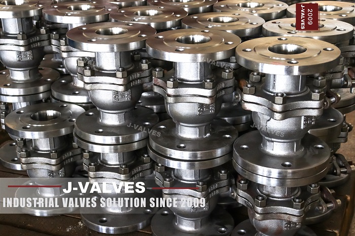
J-VALVES, a distinguished professional ball valve manufacturer rooted in China, takes pride in its extensive product portfolio. Our offerings span a wide range, including trunnion-mounted ball valves, floating ball valves, high-temperature ball valves, high-pressure ball valves, metal-sealed ball valves, ultra-low temperature ball valves, DBB ball valves, Three-way And Four-way Ball Valve, and fully welded ball valves. Each product is a testament to our commitment to precision engineering and reliable performance. Meticulously crafted, they are designed to not only meet but exceed the most stringent industrial demands, ensuring stable operation even under extreme conditions. This enables us to provide our clients with high-value services and makes our valves widely sought-after in industries.
Product Category
Contact Us


-
J-VALVES-Q341F
-
J-VALVES
Overview of the J-VALVES DN50 x 20 Class 1500 Extended Stem Floating Ball Valve

The J-VALVES DN50 x 20 Class 1500 floating ball valve is a two piece bolted body valve with a 2 inch flanged end and a 20 mm flow bore, forged in ASTM A182 F44 super austenitic stainless steel and fitted with an extended stem that lifts the packing gland and the operator clear of insulation, a cold box wall or the ground. Three requirements meet here and no standard catalogue valve satisfies all of them: a 250 bar class pressure boundary, a chloride bearing medium that pits 316 stainless, and an operator position that has to sit away from the line.
The 20 mm bore is why the floating geometry still works at Class 1500. A floating ball seals because line pressure drives it onto the downstream seat, so seat load scales with the area that pressure acts on. At the Class 1500 ambient rating of about 255 bar, a 20 mm bore puts roughly 8 kN on the seat face, where the 49 mm full bore of a standard NPS 2 valve would put roughly 48 kN on it, six times as much and well beyond lever range. Cutting the bore keeps this valve inside one hand at a class where trunnion mounting is the normal answer.
Design and Construction
The body is a two piece bolted split design: a main body and an end adapter closed on one machined joint with a spiral wound SS316 gasket with graphite filler and a ring of bolts. Only one main pressure joint has to be controlled, and because the ball floats the two halves carry the seat rings directly, with no trunnion blocks and no bearing housings.
The ball is a 20 mm bore ball in A182 F44 with hard chrome plating 0.05 to 0.10 mm thick at about 800 to 1000 HV, and the stem is F44 or 17-4PH stainless. The stem is separate from the ball and carries no side load from line pressure. Seats are soft inserts energised by line pressure alone, with no piston and no spring behind them. Datasheets for this product routinely list single and double piston effect seats, seat sealant injection and trunnion bearings, but those belong to a trunnion mounted valve, and a floating ball valve has none of them.
The extended stem carries the gland and the operator above the cold or hot zone. On an insulated line its job is clearance, so the gland bolts can be tightened and the packing renewed without cutting the lagging. On a cryogenic line it is a thermal break, and the column of vapour inside it is what keeps the packing above 0 degrees C. On a buried line it simply brings the operator to grade. Only the first two depend on orientation.
Material Options
F44 is a 6 percent molybdenum super austenitic stainless steel, UNS S31254, also sold as 254SMO and listed as EN 1.4547. Its chromium, molybdenum and nitrogen content give a pitting resistance equivalent number of about 42 to 44, which is the reason a valve is forged from it: it holds up in chlorides and seawater where 316L pits and crevices corrode.
Strength is moderate rather than high. Minimum tensile strength is 650 MPa, minimum 0.2 percent proof strength about 300 MPa, elongation at least 35 percent, and proof strength falls from about 230 MPa at 100 C to 190 MPa at 200 C, 170 MPa at 300 C and 160 MPa at 400 C. It is not a high temperature strength material.
One trap is worth knowing. Intermetallic phases precipitate in the alloy between 600 C and 1000 C, so it must not be held in that band and is not a creep service material. A valve sold as F44 for a 425 C duty is sold on the body rating of the pressure class, and the seat sets the real limit.
| Component | Standard Material | Optional or Alternative | Service Notes |
|---|---|---|---|
| Body and adapter | ASTM A182 F44 forged (UNS S31254) | A995 grade 4A cast, other alloy on request | Super austenitic, for chloride service |
| Ball | ASTM A182 F44 | Hard chrome 0.05-0.10 mm at 800-1000 HV, nitrided | Chrome resists scoring under seat load |
| Stem | ASTM A182 F44 | 17-4PH stainless | Separate from the ball, so no side load |
| Seat ring | RPTFE | PEEK, PPL, PCTFE, F44 with Stellite hardfacing | Seat grade sets the temperature limit |
| Stem packing | High density flexible graphite | PTFE, cryogenic qualified packing | Cold grades for cryogenic builds |
| Body gasket | Spiral wound SS316 with graphite filler | PTFE envelope, metal jacketed | Seals the single main body joint |
| Bolting | A193 B7 / A194 2H | B8M class 2, B7M for sour service | Eight 7/8 inch bolts at each flange |
| Extended stem | ASTM A182 F44 | SS316, matching alloy | Length set by the insulation or cold duty |
| End connection | ASME B16.5 Class 1500 ring type joint | Raised face or hub ends | Ring type joint is standard at this rating |
Technical Specifications
The table lists the standard envelope. Values move when the seat grade, the end facing, the stem length or the operator is changed on the order.
| Item | Value |
|---|---|
| Nominal size | DN50 x DN20 (2 inch x 3/4 inch) |
| End size | DN50 / NPS 2 |
| Flow bore | 20 mm (0.79 inch), special reduced port |
| Body style | Two piece, bolted split body |
| Pressure class | Class 1500, catalogue label PN 260 |
| Ambient rating | 255.3 bar (3705 psi) at 38 C to ASME B16.34 |
| Body temperature range | -29 C to 425 C |
| Seat temperature limit | 200 C with RPTFE, 260 C with PEEK or PPL |
| End connection | ASME B16.5 Class 1500 flanged, ring type joint |
| Flange outside diameter | 215.9 mm |
| Flange thickness | 38.1 mm |
| Bolt circle and bolting | 165.1 mm, 8 x 7/8 inch |
| Ring joint | R24, 95.25 mm pitch diameter, 7.92 mm wide, 11.91 mm deep |
| Face to face | 292 mm reference to ASME B16.10 Class 1500, confirm on the drawing |
| Extended stem | 300 mm to 1200 mm, set by the duty |
| Shell test | 383 bar, 1.5 times the ambient rating |
| Seat test | 281 bar, 1.1 times the ambient rating |
| Anti-static | 10 ohm or less |
| Operation | Lever, worm gear, pneumatic, electric or hydraulic |
Standards and Compliance
The design basis is API 608, the general industrial ball valve standard, with ASME B16.34 for the pressure temperature rating and minimum wall thickness. API 608 is the correct basis for a floating ball valve and carries the details that separate a compliant product from a look alike: stem retention against blow out, a stem to ball connection transmitting at least 20 N·m, torsional failure outside the pressure boundary, an anti-static path at 10 ohm or less, clockwise closing, defined bore minimums and no hollow ball.
API 6D appears on many datasheets for this product alongside API 608, but it is written around a trunnion mounted pipeline valve. Its double block and bleed requirement and its seat, test and bore provisions describe two independently loaded seats on a supported ball, and this valve has neither. Naming both standards says nothing about which one the valve was built to.
Class 1500 is the second thing buyers get wrong. The nearest EN flange rating is PN 250, and the standard EN steps run 250 and then 320 with nothing between, so PN 260 is catalogue shorthand for the 1500 pound class rather than an EN 1092-1 rating. The flanges here are ASME B16.5 Class 1500, and a Class 1500 flange will not bolt to a PN 250 or PN 320 flange of the same nominal size. At the ambient rating the hydrostatic end load on the ring groove is about 182 kN, carried by eight 7/8 inch bolts through a metal ring gasket, and the joint gives trouble before the body wall does, which is why the end is a ring type joint rather than a raised face.
| Requirement | Standard | Supplied |
|---|---|---|
| Ball valve design | API 608 | Yes |
| Pressure rating and wall thickness | ASME B16.34 | Yes |
| Flange and ring joint dimensions | ASME B16.5 | Yes |
| Face to face and end to end | ASME B16.10 | Yes |
| Shell and seat test | API 598 | Yes |
| Leakage rate classes | ISO 5208 | Yes |
| Fire safe qualification | API 607 / ISO 10497 | Yes |
| Extended bonnet length and orientation | BS 6364 / MSS SP-134 | Yes |
| Fugitive emission | ISO 15848-1 | Optional |
| Sour service material | NACE MR0175 / ISO 15156 | Optional |
| Material certificate | EN 10204 3.1 | Yes |
Manufacturing Process
Forged F44 bodies and covers are machined at the J-VALVES plants in Wenzhou and Lishui, on a 15000 square metre base running 40 CNC lathes, 5 machining centres and 8 drilling machines. The bore, the seat pockets, the stem bore, the ring joint grooves and the flange faces are cut against the drawing, because seat pocket concentricity and face to face length set the sealing performance and the installation fit. F44 work hardens, has low thermal conductivity and moves when it is cut, so roughing and finishing are separated and the alloy is bought in the solution annealed condition.

Quality Control and Testing
Every valve passes a nine step inspection sequence before it leaves the plant, tied back to the heat number so the pressure test report and the material certificate form one document package.
| Step | What Is Checked | Acceptance |
|---|---|---|
| Incoming material | Heat number, chemistry and mill certificate | EN 10204 3.1 |
| PMI before machining | Alloy identity of the F44 forging | 100 percent |
| Rough and finish machining | Bore, seat pockets, ring joint grooves, face to face | Drawing, ASME B16.10 |
| Assembly and function | Stem retention, lever travel, stop position | Smooth travel, no bind |
| Shell test | Body and body joint at 1.5 times the rating | 383 bar, no leakage |
| Seat test | Each seat at 1.1 times the rating, both directions | 281 bar, ISO 5208 rate A |
| Anti-static and torque | Continuity from ball to stem to body, breakaway torque | 10 ohm or less, torque recorded |
| Extended stem | Length, wall, orientation limit, drip plate position | GA drawing |
| Coating, marking and documents | Film thickness, heat number tag, certificate set | Spec, EN 10204 3.1 |
Shell testing holds the assembled body at 383 bar with water while the body joint, both flange joints and the gland are checked for weeping. Seat testing applies 281 bar to each seat in turn in both directions, and a soft seated valve is rejected on any visible leakage. Breakaway torque is recorded on every valve, because the bore is small and the seat load is low, so an actuator has to be sized from the measured figure rather than from the nominal size.

Applications and Industry Service
The small bore with a Class 1500 body points to one family of duties: small flows isolated or controlled at full line pressure. Injection points, chemical dosing and metering lines, sampling and analyser take off connections, pressure instrument isolation and high pressure test benches all use it, and the reduced bore is an advantage there, because a low flow rate is the point and the smaller seat area is what makes a hand lever possible.
Chloride bearing service is the second driver. Seawater injection, brine and chloride process streams, coastal and offshore installations and desalination and cooling water systems use F44 where 316L would pit, as do pulp mill bleach plants and flue gas desulfurisation scrubber circuits.
Insulated and buried service is the third. On hot oil, steam and jacketed lines the extension lifts the packing out of the lagging, on buried lines it brings the operator to grade without a pit, and on cryogenic duty with a PCTFE seat and cold qualified packing it keeps the gland above freezing. Cryogenic builds are quoted against a stated minimum temperature, because seat, packing and stem length all change with it.
Installation, Operation and Maintenance
Before installation, clean the flange faces, the ring grooves and the bore, cycle the valve once by hand and check the body joint bolts. Ring gaskets are replaced on every break of the joint and the groove faces must be free of scoring. A valve of this height should be supported independently, particularly when the extension is long, so its weight and any side load from the operator are not carried by the flange bolts.
The orientation rule causes most field failures. A cryogenic extended stem relies on a column of vapour inside the extension to keep the packing warm, and that only works if the stem points up. BS 6364 sets the limits: at or above horizontal for gas service, at or above 45 degrees above horizontal for liquid service outside a cold box, and at or above 15 degrees above horizontal inside a cold box. A cryogenic valve installed horizontally or upside down fills the extension with liquid and the packing freezes. An extension fitted only for insulation clearance or for a buried line does not carry that restriction.
BS 6364 also sets minimum gland extension lengths: 250 mm outside a cold box, and for a ball valve in a cold box 500 mm at DN 15 to DN 50 and 700 mm at DN 80 to DN 100. The drip plate welded to the extension catches the melt water that runs off the cold upper section and throws it clear of the insulation and the body bolts.
In service the valve needs no routine lubrication, and the regular check is that the lever or gearbox reaches both stops. If a seat passes, cycle the valve open and closed two or three times to clear a trapped particle. If leakage continues, isolate the line, vent and drain both sides, confirm the cavity is depressurised and open the body joint. That breaks the pressure boundary, so the valve must be isolated and vented first, and the bolt torque and sequence followed on reassembly. Replace both seats as a set, renew the body gasket and re-test at 1.1 times the rated pressure.
How to Specify and Order
To order, state the size and both bores, the pressure class, the end connection and facing, the body and trim alloy, the seat material, the stem length and its duty, and the operator. The 20 mm bore is a special reduced port below the standard reduced port figure of about 37 mm for an NPS 2 valve, so the flow coefficient must be quoted from the drawing rather than assumed from the nominal size. State the design standard as API 608 with ASME B16.34 and the test standard as API 598, and say whether the flanges are ring type joint or raised face.
Give the extended stem duty explicitly, since length, wall thickness and orientation limit all follow from it, and say whether a drip plate is required. State a sour medium, because F44 is supplied to NACE MR0175 / ISO 15156 on request. Standard builds ship in 2 to 4 weeks and custom builds in 4 to 8 weeks, with an EN 10204 3.1 material certificate, a dimensional report, a pressure test report carrying the shell, seat and torque records, and a packing list. OEM and private label supply are available.
FAQ
Q: What does DN50 x 20 mean on this valve?
A: DN50 is the end or flange size, 2 inch, and 20 is the flow bore in millimetres, about 3/4 inch. The valve is a special reduced port design: the standard reduced port bore for an NPS 2 valve is about 37 mm, so the 20 mm bore is smaller again and the flow coefficient must be taken from the drawing rather than from the nominal size.
Q: Why is a floating ball valve used at Class 1500 instead of a trunnion mounted valve?
A: Because the 20 mm bore keeps the seat load low. At the Class 1500 ambient rating of about 255 bar a 20 mm bore puts roughly 8 kN on the seat face, where a full bore NPS 2 valve would put roughly 48 kN. The floating geometry stays inside lever range at that load, so the simpler body is used. At full bore, or at larger sizes in the same class, the load grows quickly and a trunnion mounted valve is the correct choice.
Q: How long should the extended stem be?
A: It depends on the duty. BS 6364 sets a minimum gland extension of 250 mm where the valve is not in a cold box, and for a ball valve inside a cold box 500 mm at DN 15 to DN 50 and 700 mm at DN 80 to DN 100. Where the extension is fitted only to clear pipe insulation or to bring a buried operator to grade, the length is set by the insulation thickness or the burial depth. A cryogenic extension must be installed with the stem pointing up.
Q: Is F44 the right material for a high temperature valve?
A: Not on temperature alone. F44, or UNS S31254, is chosen for chloride and seawater resistance, and its proof strength falls from about 300 MPa at room temperature to about 170 MPa at 300 C. Intermetallic phases form between 600 C and 1000 C, so the alloy must not be held in that band. The 425 C figure is the body rating of the pressure class; the seat, at 200 C with RPTFE and 260 C with PEEK or PPL, sets the real limit.


Hot Products


News
Ball Valves in A Kraft Pulp Mill: Black Liquor, Green Liquor And The Cost of Choosing The Alloy by Habit
White liquor at pH 14 cracks carbon steel welds, black liquor sets solid below 100 C, green liquor dregs grind seats: alloy choice and torque in a kraft mill.
Read More
Slug Flow And Ball Valves: What Actually Arrives At The Seat
A slug is liquid mass with momentum, not a pressure spike. What changes at the seat, in the cavity and at the actuator when liquid reaches a ball valve.
Read More
Ball Valves in Direct Lithium Extraction: PH 1 Eluate, Gypsum Scale And 438,000 Cycles in Twenty-Five Years
Direct lithium extraction swings valves from pH 1 eluate to pH 12 caustic, 48 column switches a day and gypsum scale. Materials, seats and torque.
Read More
Ball Valves in Geothermal Brine: Silica Scale, Chloride Cracking And The Cooling Trap
Why geothermal brine destroys ball valves: retrograde silica scale, calcite at the flash point, chloride cracking above 60 C and the 250 C seat limit.
Read More