


CHINA J-VALVES Offers Various High-quality I ndustrial Ball Valves
J-VALVES, a distinguished professional ball valve manufacturer rooted in China, takes pride in its extensive product portfolio. Our offerings span a wide range, including trunnion-mounted ball valves, floating ball valves, high-temperature ball valves, high-pressure ball valves, metal-sealed ball valves, ultra-low temperature ball valves, DBB ball valves, Three-way And Four-way Ball Valve, and fully welded ball valves. Each product is a testament to our commitment to precision engineering and reliable performance. Meticulously crafted, they are designed to not only meet but exceed the most stringent industrial demands, ensuring stable operation even under extreme conditions. This enables us to provide our clients with high-value services and makes our valves widely sought-after in industries.
Product Category
Contact Us


-
J-VALVES-Q41F
-
J-VALVES
Overview of the J-VALVES 1/2 Inch Class 300 Two Piece Cast Steel Floating Ball Valve

The J-VALVES 1/2 inch (DN15) Class 300 two piece cast
steel floating ball valve is a small bore, full port isolation valve for instrument, utility and chemical service where a compact flanged body is required. It is built with a 13 mm full bore, an A216 WCB cast steel body and ASME B16.5 Class 300 raised face flanges, and it is designed to API 608 under the wall thickness and pressure temperature limits of ASME B16.34.
The floating ball geometry is the right choice at this bore size. Line pressure pushes the ball onto the downstream seat, so seat load rises with pressure, but at DN15 the force stays small enough for a lever to handle, and the valve opens and closes within about 10 to 25 N·m against the 360 N manual input limit of API 608. Above roughly DN200 (8 inch) or Class 600 the same geometry produces seat loads a lever cannot manage, and a trunnion mounted valve takes over.
The valve isolates instrument root connections, sample points, drain and vent lines, small bore utility branches, dosing skids and analyser take off points. Seat selection lets one body cover a wide duty range: PTFE and RPTFE for general process and utility service, and PPL where the line runs hot.
Design and Construction
The body is a two piece bolted split design: a main body and an end adapter joined by four bolts through a graphite filled spiral wound gasket. The pattern allows the ball and seats to be reached without cutting the valve out of the line, which matters on instrument skids where the valve sits in a tight assembly.
The ball is a 13 mm full bore ball in A182 F316 stainless steel, finished with hard chrome plating 0.05 to 0.10 mm thick at about 800 to 1000 HV, or with electroless nickel plating where a smoother coating is wanted. The chrome layer is what stops the ball surface from scoring when the seat is loaded against it at full differential pressure.
Seats are moulded inserts carried in the body and the adapter and energised by line pressure alone. With no spring behind the seat, loading follows the differential across the valve, which keeps the seal reliable at low pressure and the torque predictable at high pressure. Stem sealing uses a PTFE V ring stack, and the stem is retained under a shoulder so it cannot be ejected by line pressure even if the gland is opened.
API 608 controls the safety details separating a compliant valve from a look alike. The stem to ball connection transmits at least 20 N·m, the stem is designed so torsional failure occurs outside the pressure boundary, the lever turns clockwise to close, and an anti-static device links ball, stem and body at 10 ohm or less. The lever carries open and closed stops, and the standard build uses a solid ball, since API 608 does not allow a hollow ball without written purchaser agreement.

Material Options
The body and adapter are A216 WCB cast steel as standard. Under ASME B16.34 group 1.1 this covers -29 C to 425 C and suits water, oil, gas and general chemical service. CF8M and CF3M stainless are supplied for corrosive media and LCC low temperature carbon steel for cold service, and because small castings are available across a wide material range, the same 1/2 inch pattern can be produced in duplex or nickel alloy without a new mould.
The ball and stem are A182 F316 with a hard chrome or ENP finish, chosen by fluid. Hard chrome resists abrasive fines and the high contact stress a fully loaded seat creates, while ENP gives a more even coating and lower friction in clean media. The seat insert sets the temperature limit of the whole valve: PTFE and RPTFE for the general range, PPL when the process runs hot, and metal to metal where the fluid is abrasive or the duty fire exposed.
Sour service versions are supplied to NACE MR0175 / ISO 15156 with hardness controlled trim, and every pressure retaining part carries an EN 10204 3.1 certificate with its heat number recorded against the test report.
| Component | Standard Material | Optional Upgrade | Service Notes |
Body and adapter | A216 WCB cast steel | CF8M, CF3M, LCC | WCB covers -29 C to 425 C under group 1.1 |
Ball | A182 F316 | Hard chrome 0.05-0.10 mm at 800-1000 HV | Chrome resists scoring under full seat load |
Stem | A182 F316 | ENP surface | Blow-out proof and anti-static connected |
Seat | PTFE | RPTFE, PPL, metal to metal | Seat choice sets the temperature limit |
Body gasket | Spiral wound SS316 graphite | PTFE coated | Seals the two piece bolted body joint |
Stem seal | PTFE V ring stack | Graphite packing | Graphite is required above 200 C |
Bolting | A193 B7 / A194 2H | A320 L7 | Four bolts at the body joint |
Lever | Carbon steel with PVC sleeve | SS304 lever | Fitted with open and closed stops |
Technical Specifications
The table lists the standard envelope of the valve. Values apply to the standard trim and move when the seat, the surface finish or the end connection is changed on the order.
Item | Value |
Nominal size | 1/2 inch (DN15) |
Bore | 13 mm full bore, full port |
Pressure class | ASME Class 300 |
Body style | Two piece, bolted split body |
Body material | A216 WCB cast steel |
Ball and stem | A182 F316, hard chrome or ENP |
Seat material | PTFE, RPTFE or PPL |
End connection | ASME B16.5 Class 300 raised face flange, 4 x 1/2 inch bolts on a 66.7 mm bolt circle |
Face to face | 140 mm to ASME B16.10 |
Operation | Lever, 180 degree travel, clockwise to close |
Pressure rating | 51.1 bar (740 psi) at 38 C, 38.0 bar (551 psi) at 425 C |
Temperature | -29 C to 200 C with PTFE, to 260 C with PPL |
Shell test | API 598, 1.5 x rated, 76.7 bar |
Seat test | API 598, 1.1 x rated, 56.2 bar |
Anti-static | API 608, resistance 10 ohm or less |
Fire safe | API 607 / ISO 10497 |
Standards and Compliance
The design basis is API 608, supported by ASME B16.34 for the pressure temperature rating and minimum wall thickness. Face to face length follows ASME B16.10, the raised face flange follows ASME B16.5, and the acceptance criteria for the shell and seat tests follow API 598.
For the 1/2 inch Class 300 combination the numbers work out as follows. ASME B16.34 group 1.1 rates the body at 51.1 bar (740 psi) at 38 C, falling to 46.6 bar at 100 C, 44.1 bar at 200 C, 42.5 bar at 300 C and 38.0 bar at 425 C. The drop from 38 C to 300 C is about 17 percent, which is why a valve selected from a cold rating alone is over rated in a hot line. API 598 then requires the shell test at 1.5 times the 38 C rating, or 76.7 bar, and the seat test at 1.1 times the rating, or 56.2 bar, with zero visible leakage accepted on a soft seated valve.
Fire safe behaviour follows API 607 and ISO 10497: a 750 C to 800 C flame for 30 minutes, cooling, then a repeat seat leakage test. A fire safe valve still seals through a metal backup seat after the soft seat is destroyed; it is not a guarantee that the valve stays operable after a fire. Low emission stem sealing to ISO 15848-1, PED 2014/68/EU documentation and witnessed third party testing are available where the project requires them.
| Requirement | Standard | Supplied |
Ball valve design | API 608 | Yes |
Pressure rating and wall thickness | ASME B16.34 | Yes |
Face to face length | ASME B16.10 | Yes |
Raised face flange | ASME B16.5 | Yes |
Shell and seat test | API 598 | Yes |
Fire safe test | API 607 / ISO 10497 | Yes |
Fugitive emission | ISO 15848-1 | Optional |
Sour service material | NACE MR0175 / ISO 15156 | Optional |
Material certificate | EN 10204 3.1 | Yes |
Manufacturing Process
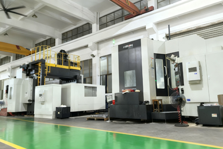
J-VALVES runs this process chain in house at its Wenzhou and Lishui plants, covering a 15000 square metre manufacturing base. Cast bodies start with mould and pour control so the WCB and stainless castings hold the required wall section. All pressure retaining faces, seat pockets, the stem bore and the flange faces are machined on CNC lathes and machining centres against drawings, with 40 CNC lathes, 5 machining centres and 8 drilling machines in the plant, so seat pocket concentricity and the 140 mm face to face length are held.
After machining the valve moves to assembly, where seats, chrome plated ball, blow-out proof stem, anti-static spring and body bolts are fitted and torqued to a controlled procedure. Each valve is pressure tested on the bench, the lever torque measured and the anti-static resistance checked, before coating, heat number tagging and packing. Third party inspection can be arranged at any stage.
Quality Control and Testing
Every valve passes an eight step inspection sequence before it leaves the plant. The sequence follows the part from incoming material to finished valve and links each measurement to the heat number, so the test report and material certificates form one complete document package.
| Step | What Is Checked | Standard or Acceptance |
Incoming material | Heat number, chemistry, mill certificate | EN 10204 3.1 |
PMI before machining | Alloy identity of stainless, duplex and nickel alloy bodies | 100 percent on alloy bodies |
Machining dimension | Bore, seat pocket, face to face length | ASME B16.10, drawing |
Assembly and function | Lever travel, stop position, free movement | Smooth, no bind |
Shell strength test | Body and adapter at 1.5 x rated | API 598, 76.7 bar, no leak |
Seat test | Both seats at 1.1 x rated, both directions | API 598, 56.2 bar, zero visible leak |
Anti-static and torque | Continuity from ball to body, lever torque | API 608, 10 ohm or less |
Coating, marking, documents | Film thickness, heat number tag, certificate set | Spec, EN 10204 3.1 set |
Shell testing pressurises the assembled body to 76.7 bar with water and holds it while the body joint and the adapter joint are checked for weeping. Seat testing applies 56.2 bar to each seat in turn in both directions, and a soft seated valve is rejected if any visible leakage appears. Cryogenic testing to -196 C with liquid nitrogen is available for cold service, and the results join the coating thickness and adhesion records in the document package.

Paint Testing

PMI Testing

Dimension Inspection
 PT Testing

Pressure Testing Equipment
Applications and Industry Service
The valve is specified where a small line has to be isolated positively and often. Instrument root valves and gauge connections use it because the full bore keeps the impulse line clear and the lever gives an unmistakable position indication. Sample points, drains and analyser take off lines use it because the two piece body can be serviced on site, and chemical dosing skids use it because PTFE and PPL seats tolerate a wide range of aggressive fluids.
On Class 300 piping the valve matches the flange rating of the main line without an adapter. The 140 mm face to face length fixed by ASME B16.10 means a replacement drops into the existing space, and the standard ASME B16.5 raised face pattern means no special gasket or bolt is needed. Power plants and refineries use the same valve on steam tracing, condensate and lube oil lines, where the PTFE seat is sufficient and the Class 300 body is chosen to match the adjacent pipe class rather than because of the pressure.
Where the line runs hot, the PPL seat extends the range to 260 C and covers steam and heat transfer oil duties. Where the medium is abrasive or the valve sits in a fire exposed area, a metal to metal seated version is available.
Installation, Operation and Maintenance
Before installation the flange faces and bore should be cleaned and checked for foreign objects, and the valve cycled once by hand. The valve is bidirectional, so it fits either way round, but the lever should end up where an operator can reach and read it. Flanged joints are made up with the specified gasket and bolt torque, and the four body bolts checked for tightness before pressurising.
In service the valve needs no routine lubrication, and the only regular check is that the lever reaches both stops. If a seat begins to pass, cycle the valve fully open and closed two or three times, which often clears a particle trapped between ball and seat. If leakage continues, isolate the line, release the four body bolts and remove the adapter, which exposes the ball and both seats without disturbing the pipe. Replace worn seats as a pair, replace the ball if the chrome layer is broken through, and renew the body gasket on reassembly.
On a valve in hot service, re-torque the body bolts after the first thermal cycle and check the stem gland for weepage. Any fire exposed valve must be stripped, because the PTFE seat will have been destroyed even if the valve still appears to seal on the metal backup. After any maintenance the valve is re-tested at 1.1 times the rated pressure before returning to service.

How to Specify and Order
To order, state the size, pressure class, body and trim material, seat material and end connection, and confirm whether the valve is required with a lever, a gearbox or an actuator. Give the design standard, usually API 608, and the flange standard, usually ASME B16.5 Class 300 raised face. Where the line carries a corrosive or sour medium, state the fluid and temperature so the seat and coating can be selected, and say whether NACE MR0175 / ISO 15156 material is needed.
Standard specifications are accepted from one piece, with a standard lead time of 2 to 4 weeks and 4 to 8 weeks for custom builds. Every order ships with an EN 10204 3.1 material certificate, a dimensional report, a pressure test report carrying the torque and anti-static records, a coating report and a packing list. OEM and private label supply are available, and export packaging uses a wooden case with the bore plugged and the flange faces protected.
FAQ
Q: What is the pressure rating of a 1/2 inch Class 300 ball valve?
A: A 1/2 inch Class 300 floating ball valve in A216 WCB has a rating of 51.1 bar (740 psi) at 38 C under ASME B16.34 group 1.1. The rating falls to 46.6 bar at 100 C, 44.1 bar at 200 C, 42.5 bar at 300 C and 38.0 bar at 425 C, so the working pressure must be checked against the actual line temperature and not against the cold rating.
Q: Why is a two piece body used instead of a one piece body at this size?
A: A two piece bolted body lets the ball and both seats be reached by removing the end adapter, so the valve can be serviced or re seated without cutting it out of the line. On instrument and small bore skids the valve usually sits in a tight assembly, so in line serviceability is worth more than the small cost saving of a one piece body.
Q: What is the difference between PTFE, RPTFE and PPL seats?
A: PTFE covers general service to about 200 C, RPTFE is a glass reinforced grade with better creep resistance at the same temperature, and PPL extends the working range to about 260 C. The seat sets the temperature limit of the whole valve, so the seat grade must be chosen from the line temperature, not from the body material.
Q: Is the valve fire safe and anti-static?
A: Yes. The standard build is fire safe to API 607 / ISO 10497 with a metal backup seat that holds after the soft seat is destroyed, and it includes an anti-static device that keeps the resistance from ball to stem to body at 10 ohm or less as required by API 608.


Hot Products


News
Ball Valves in A Kraft Pulp Mill: Black Liquor, Green Liquor And The Cost of Choosing The Alloy by Habit
White liquor at pH 14 cracks carbon steel welds, black liquor sets solid below 100 C, green liquor dregs grind seats: alloy choice and torque in a kraft mill.
Read More
Slug Flow And Ball Valves: What Actually Arrives At The Seat
A slug is liquid mass with momentum, not a pressure spike. What changes at the seat, in the cavity and at the actuator when liquid reaches a ball valve.
Read More
Ball Valves in Direct Lithium Extraction: PH 1 Eluate, Gypsum Scale And 438,000 Cycles in Twenty-Five Years
Direct lithium extraction swings valves from pH 1 eluate to pH 12 caustic, 48 column switches a day and gypsum scale. Materials, seats and torque.
Read More
Ball Valves in Geothermal Brine: Silica Scale, Chloride Cracking And The Cooling Trap
Why geothermal brine destroys ball valves: retrograde silica scale, calcite at the flash point, chloride cracking above 60 C and the 250 C seat limit.
Read More