


CHINA J-VALVES Offers Various High-quality I ndustrial Ball Valves
J-VALVES, a distinguished professional ball valve manufacturer rooted in China, takes pride in its extensive product portfolio. Our offerings span a wide range, including trunnion-mounted ball valves, floating ball valves, high-temperature ball valves, high-pressure ball valves, metal-sealed ball valves, ultra-low temperature ball valves, DBB ball valves, Three-way And Four-way Ball Valve, and fully welded ball valves. Each product is a testament to our commitment to precision engineering and reliable performance. Meticulously crafted, they are designed to not only meet but exceed the most stringent industrial demands, ensuring stable operation even under extreme conditions. This enables us to provide our clients with high-value services and makes our valves widely sought-after in industries.
Product Category
Contact Us


-
J-VALVES-Q41F
-
J-VALVES
Overview of the J-VALVES 2x1.5 Inch 150LB WCB Two Piece Floating Ball Valve with Handle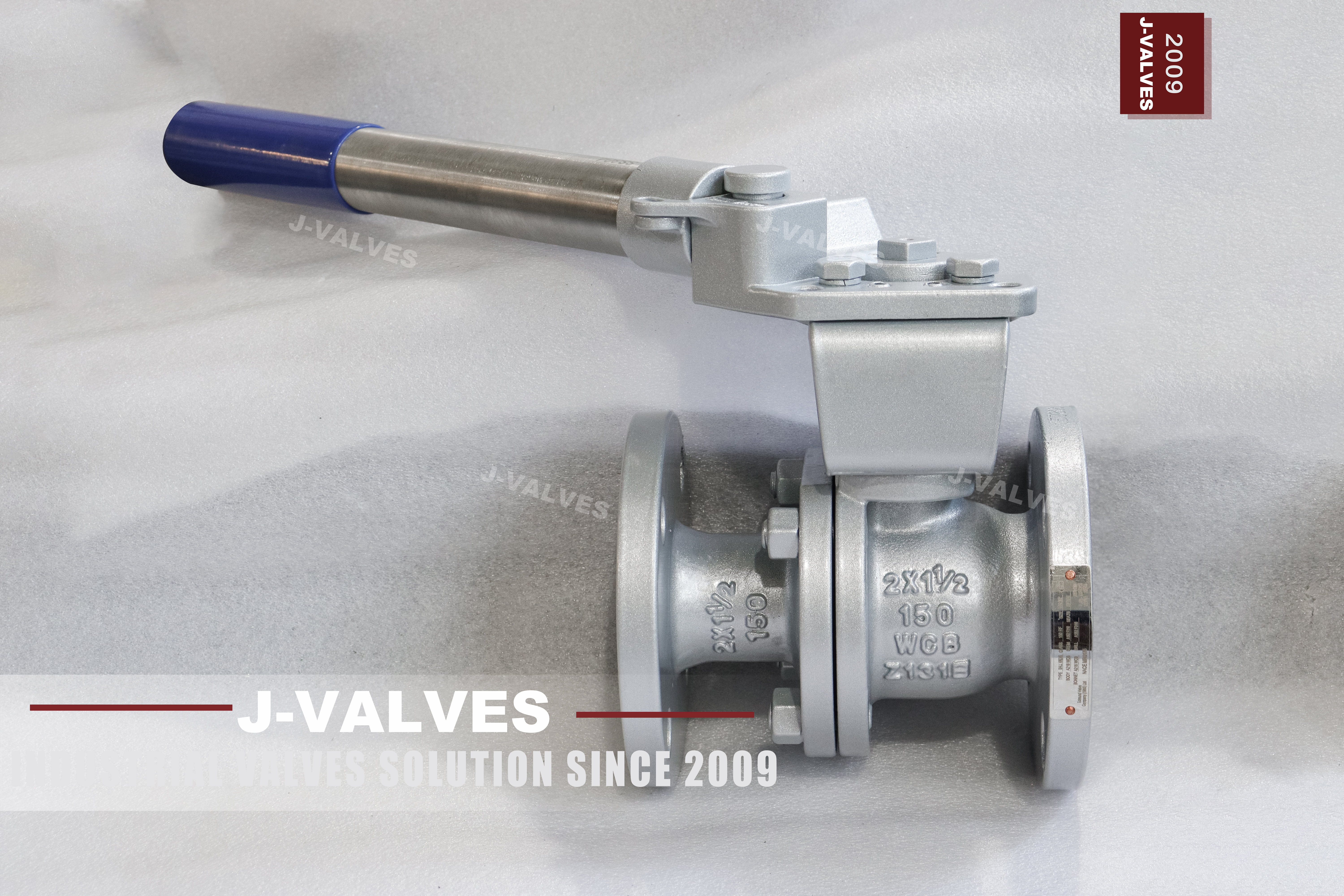
A lever on a small ball valve is treated as an accessory: something that comes in the box, gets replaced when it is lost, and is sometimes extended with a piece of pipe when the valve feels stiff. It is not an accessory. The lever is the only point where a person applies force to the valve, and its length is the number that decides how much torque the stem, the ball and the seats will ever be asked to take.
The same lever is also the valve position indicator, and it is a poor one: two positions, ninety degrees apart, with nothing in between that means anything. That is fine for an isolation valve and useless for anything that needs modulation. Both of those facts come from the same part, which is why this page is about the handle rather than about the body, the seat or the class.
Design and Construction
The body is two pieces with one bolted joint, and the ball floats between two seats. At this size the floating design is simple and adequate: pressure pushes the ball onto the downstream seat and the seat does the sealing, with no trunnion and no springs. The stem passes through the body into the ball, retained so that it cannot be blown out, and the packing sits around it in the body.
The lever is keyed or splined to the top of the stem and held by a nut. That joint is what transmits the hand force, and it is also the first place where a mismatch shows: a lever that has been forced onto a stem with a damaged keyway will turn, but it will turn a few degrees before the stem does, and the ball will not reach its stop.

Material Options
The body is cast carbon steel and the nameplate carries the casting code. What that buys is the ordinary range of water, oil, gas and steam duties where a carbon steel shell is adequate, at the lowest cost of any body material. What it does not buy is chloride resistance, and the coating on the outside is what protects the casting where the atmosphere is wet.
The ball is carbon steel with hard chrome plating, or a stainless grade where the medium asks for it. The stem is 304 or 316 stainless, which is worth noting on a carbon steel valve: the part that turns is stainless even when the body is not, so the packing runs against a corrosion resistant surface. Seats are PTFE, reinforced PTFE or PPL, and a metal seal is available on request rather than as standard.
| Component | Standard Material | Optional Upgrade | Service Notes |
|---|---|---|---|
| Body halves | cast carbon steel, code as stamped | the same casting grade | one bolted joint |
| Ball | carbon steel with hard chrome | stainless grade | floats onto the downstream seat |
| Stem | 304 stainless | 316 stainless | stainless even on a carbon body |
| Seat | PTFE | reinforced PTFE or PPL | sets the service temperature |
| Packing | PTFE | flexible graphite | gland adjustable |
| Metal seat | available on request | not standard | seals to a leakage class |
| Ends | raised face to ASME B16.5 | Class 150 only | two inch pattern |
| Operator | lever, ninety degree, locking hole | bare stem for an actuator | not a control element |
Technical Specifications
The bore is DN40 inside a DN50 body, so the valve is one size down in the run while the flanges stay at two inch. The flange is raised face to ASME B16.5 Class 150, and the face to face follows ASME B16.10 for the size and class. The lever swings through ninety degrees, and the locking hole in the handle takes a padlock or a tag in either the open or the closed position, which is what makes the valve usable as an isolation point.
Two dimensions belong to the drawing rather than to this page: the lever length and the clearance it needs to swing. A lever that fouls a wall at ninety degrees has effectively half a valve, and the swing is often forgotten when a valve is fitted close to a header or inside a cabinet. The bore and the flange pattern come from the size data sheet.
| Item | Value |
|---|---|
| Nominal size | 2 x 1.5 inch (DN50 x DN40) |
| Pressure class | Class 150 (PN 20, the API 6D pressure code) |
| Body style | two piece, one bolted joint |
| Ball support | floating, no trunnion |
| Bore | reduced bore, DN40 through the ball |
| Body material | cast carbon steel, catalogue code as stamped |
| Ball material | carbon steel with hard chrome, stainless grade optional |
| Stem | 304 or 316 stainless |
| Seat | PTFE, reinforced PTFE or PPL; metal seat on request |
| Packing | PTFE or flexible graphite |
| End connection | raised face flange, ASME B16.5 Class 150 |
| Face to face | dimension on the signed GA drawing, held to ASME B16.10 |
| Operator | lever, ninety degree, with a locking hole |
| Lever length | as supplied; not to be extended at site |
| Torque record | dry operating torque recorded at the lever |
| Duty | on off isolation, not throttling |
| Design standard | ASME B16.34 and API 608 |
| Test standard | API 598 shell and seat test |
| Test pressure | shell 1.5 times and seat 1.1 times the class rating |
| Temperature range | minus 29 to plus 425 Celsius, metal temperature |
| Temperature limit | set by the seat compound, not by the body |
| Fire test | not claimed on this page, API 607 to be specified |
| Anti static device | not described on this page |
| Marking | size, class, body code, heat number |
| Documentation | EN 10204 3.1 on request |
| Weight | quoted with the drawing for the size and trim ordered |
Standards and Compliance
ASME B16.34 fixes the minimum wall and the rating for the casting group at Class 150. API 608 is the quarter turn product standard and covers the stem retention, the seat and the marking; it is also the document that treats the valve as an on off device rather than a control element. API 598 supplies the shell and seat acceptance numbers, and none of the three documents treats this valve as a regulating device.
Nothing on this page claims a fire test, an anti static device or a fugitive emission class. On a fuel or solvent line all three are often required, and each is a type test on the design that has to be named with its standard. A lever operated carbon steel valve in a hydrocarbon line is the exact case where a buyer assumes fire safety and the paperwork does not support it.
| Requirement | Standard | What J-VALVES Supplies |
|---|---|---|
| Pressure boundary | ASME B16.34 | minimum wall and rating for the casting group at Class 150 |
| Ball valve design | API 608 | stem retention, seat, marking, test |
| Shell and seat test | API 598 | 1.5 times the rating for the shell, 1.1 times for the seat |
| Flange pattern | ASME B16.5 Class 150 | raised face, two inch |
| Face to face | ASME B16.10 | flanged valve length for the size and class |
| Marking | API 608 and the order | size, class, body code, heat number |
| Fire test | not claimed on this page | API 607 named on the order if required |
| Documentation | EN 10204 3.1 | issued against the heat number on request |
Manufacturing Process
The ball is the part that decides how this valve seals, so it is machined and measured before anything is built around it. Sphericity and surface finish are checked against the drawing, and the ball is checked against the seat rings that will travel with it rather than against a stock ring. The stem is machined separately and its engagement with the ball slot is checked as a pair, because a loose slot is felt at the lever as lost motion long before it shows at the seat. Each ball carries the heat number of the bar it came from.
The lever is a separate part and is fitted last. The stem end is machined to its key or spline, the lever is broached to match, and the pair is checked for fit before assembly so that there is no play at the joint. A lever with visible play will feel like a worn seat at site, because the operator reads the lost motion as the valve not being fully closed.

Quality Control and Testing
Testing follows API 598: shell at one and a half times the Class 150 rating, seat at one and one tenth times in both directions, with the valve cycled in between. On this valve the cycling also checks the lever joint, because a lever that slips will show as a valve that does not reach its stop under test rather than under pressure, which is the easier place to find it.
Two checks are specific to a lever operated valve. The first is the operating torque at the lever, recorded dry, because that number is the only baseline a site has for judging whether a stiff valve is stiff because of the seat or because somebody has bent the lever. The second is the locking hole, which is checked for alignment in both positions so that a padlock can actually pass through.
| Step | What Is Checked | Standard or Acceptance |
|---|---|---|
| Incoming castings | code, heat number, wall thickness | certificate against the stamped code |
| Body machining | seat pocket depth, stem bore squareness | in process gauging |
| Lever fit | key or spline fit, no visible play | checked before assembly |
| Shell test | no leakage through the body wall | API 598 at 1.5 times the rating |
| Seat test | no visible leakage, both directions | API 598 at 1.1 times the rating, after cycling |
| Torque record | dry operating torque at the lever | recorded as the site baseline |
| Locking hole | padlock clearance in both positions | checked before packing |

Applications and Industry Service
This valve belongs on a small isolation point: a branch take off, a gauge or instrument root valve, a drain, a small utility line, a hose connection. The duty is fully open or fully closed, the medium is clean, and the valve is operated by hand a few times a shift or left alone for months. In that role the lever is exactly the right operator and the locking hole is what makes it safe to leave closed.
It is the wrong valve where the flow has to be modulated, because a partly open soft seat erodes at the edge and then will not seal at all. It is also wrong where the medium carries solids, where the temperature is above the seat ceiling, and where somebody will fit a longer lever to make it easier to turn. That last one is not a valve problem but it destroys valves.

Installation, Operation and Maintenance
Fit the valve so that the lever can swing through its full ninety degrees without touching anything, and check the swing before the flange studs are tightened. Leave the locking hole accessible. If the lever fouls at the open position, the valve will be operated half open for years and nobody will record it as a fault, because the handle stops where the wall is.
Operate by hand only. A lever that needs a cheater bar or a length of pipe is telling you the seat has swollen, the cavity has scaled or the packing is too tight, and forcing it twists the stem before it frees anything. Maintenance is the packing from the top and the seats through the body joint; the lever and the stem nut are checked for play at the same time.
How to Specify and Order
Write the size as 2x1.5 or DN50x40, the class as 150, the body code as it will be stamped, the seat compound, the end facing, the operator with or without a locking hole, and the test standard. Two of those get left out most often: the facing, which decides whether the gasket fits, and the locking hole, which decides whether the valve can be locked out.
Ask for the drawing, the mill certificate behind the 3.1 documentation and the test sheet with the operating torque recorded. On a small valve the paperwork is usually treated as an afterthought, which is why the torque figure is so often missing and why the first complaint about a stiff valve has nothing to compare against, and the valve gets blamed for being stiff when it was always stiff.
FAQ
Q: Why does the handle matter so much on a small valve?
A: Because it is the lever arm through which every force reaches the valve. Its length decides the maximum torque the stem and seats will see, and the joint between handle and stem is a mechanical fit that can wear or be damaged. A longer handle does not make the valve easier to live with; it makes the same valve take more torque than it was designed for.
Q: Can a longer handle be fitted on site?
A: It can be fitted, and it is the most common way a small valve is destroyed. The extra length multiplies the force the operator applies, and the stem key, the stem itself and the seat take the difference. If the valve is stiff, the cause is in the seat or the packing, and a longer handle only postpones the repair while making it more expensive.
Q: Can this valve be used to control flow?
A: No. A quarter turn soft seated valve has two useful positions, and a seat held part open is being eroded at the edge by the flow. After a few weeks of throttling the seat will not seal in the closed position, and the valve has to be rebuilt or replaced. If the duty needs modulation, it needs a different valve, not a different handle position.
Q: What is the locking hole for?
A: It lets the valve be locked in the open or the closed position with a padlock or a tag, which is what makes it usable as an isolation point for maintenance. It is a small feature that gets left off an order, and a valve without it cannot be locked out, which matters on any line that has a permit to work system.
Q: What temperature can this valve be used at?
A: The printed band of minus 29 to plus 425 Celsius describes the metal. The seats listed beside it are polymers with much lower ceilings, so the usable range is set by the compound on the order. A metal seat is available on request, and it moves the ceiling but changes the leakage class at the same time.
Q: Is this the same valve as the other 2x1.5 listing?
A: Yes, the site carries a second URL for the same size and class with WCB missing from the slug. It describes the same valve, so one should be kept as the indexed page and the other redirected; two pages for one small valve simply split their own traffic.


Hot Products


News
Ball Valves in A Kraft Pulp Mill: Black Liquor, Green Liquor And The Cost of Choosing The Alloy by Habit
White liquor at pH 14 cracks carbon steel welds, black liquor sets solid below 100 C, green liquor dregs grind seats: alloy choice and torque in a kraft mill.
Read More
Slug Flow And Ball Valves: What Actually Arrives At The Seat
A slug is liquid mass with momentum, not a pressure spike. What changes at the seat, in the cavity and at the actuator when liquid reaches a ball valve.
Read More
Ball Valves in Direct Lithium Extraction: PH 1 Eluate, Gypsum Scale And 438,000 Cycles in Twenty-Five Years
Direct lithium extraction swings valves from pH 1 eluate to pH 12 caustic, 48 column switches a day and gypsum scale. Materials, seats and torque.
Read More
Ball Valves in Geothermal Brine: Silica Scale, Chloride Cracking And The Cooling Trap
Why geothermal brine destroys ball valves: retrograde silica scale, calcite at the flash point, chloride cracking above 60 C and the 250 C seat limit.
Read More