


CHINA J-VALVES Offers Various High-quality I ndustrial Ball Valves
J-VALVES, a distinguished professional ball valve manufacturer rooted in China, takes pride in its extensive product portfolio. Our offerings span a wide range, including trunnion-mounted ball valves, floating ball valves, high-temperature ball valves, high-pressure ball valves, metal-sealed ball valves, ultra-low temperature ball valves, DBB ball valves, Three-way And Four-way Ball Valve, and fully welded ball valves. Each product is a testament to our commitment to precision engineering and reliable performance. Meticulously crafted, they are designed to not only meet but exceed the most stringent industrial demands, ensuring stable operation even under extreme conditions. This enables us to provide our clients with high-value services and makes our valves widely sought-after in industries.
Product Category
Contact Us


-
J-VALVES-Q41F
-
J-VALVES
Overview of the J-VALVES DN80x50 PN20 F316 Two-Piece Extended Stem Ball Valve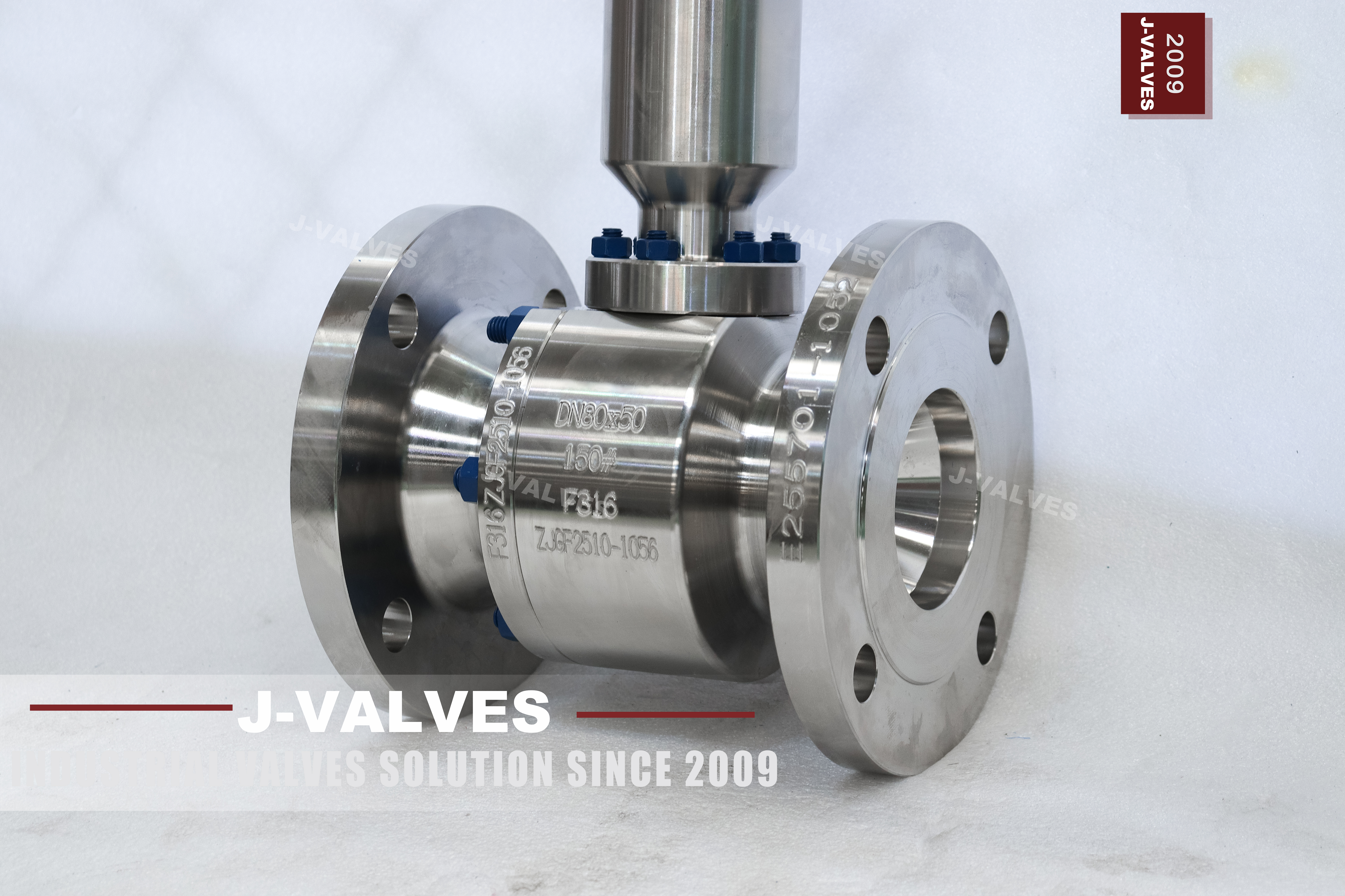
A three inch line that has to be insulated leaves one problem the pipe cannot solve: the valve still has to be turned, and the cladding sits exactly where the hand needs to go. The answer on this valve is a column that carries the lever clear of the insulation. What the column does not do is carry the stem seal with it, and that difference decides whether this valve fits the duty or whether the duty needs a different construction altogether.
The body is stamped with four lines: DN80x50, 150#, F316 and the heat number ZJCF2510-1056, with the grade and the heat repeated vertically on the barrel. DN80x50 is a three inch flanged body with a two inch passage through the ball, so the pipe stays three inch and only the bore narrows. 150# is the rating that API 6D records as PN20. F316 is the grade, and on this plate the house code and the ASTM designation happen to agree, which is worth checking rather than assuming on this product line.
Two piece means a main body and one bolted end cap with a single pressure containing joint. Floating means the ball is not carried on trunnions: line pressure pushes it into the downstream seat and the seat does the sealing. Extended stem, on this valve, means the operating head sits on a dry column above a bolted body cover, with the stem in two pieces joined by a clamp coupling inside an open yoke.
Four things decide whether this valve is right, and none of them is on the nameplate: where the stem seal actually sits, which flange drilling the line uses, what the reduced bore costs the line, and how torque reaches the ball through a column. This page takes them in that order, because the first one changes the answer to the rest.
Design and Construction
Start with the photograph, because it settles a question the description gets wrong. The stem is not one piece. Below the top plate there is a window, and in that window a clamp coupling joins the upper stem to the lower one. An open yoke of that kind cannot be a pressure boundary, so the stem seal cannot be at the top of the column. It sits at the bottom, in the cover that is bolted to the body by a ring of studs.
Two consequences follow, and both reach the purchase order. The first is temperature. The packing runs at body temperature, because it is mounted on the body, and the column changes nothing about that. On a hot line the extension moves the hand and leaves the packing where it was. The original page says the extension positions the stuffing box and the operating mechanism away from the hot zone. The mechanism, yes. The stuffing box, no.
The second is maintenance. Taking up the packing means reaching a gland that sits under the column, so it is a column off job rather than a spanner job. That is acceptable on a PTFE packing that should not need attention between shutdowns, and it is a real limitation on a duty where packing take up is routine.
If the requirement is a seal that runs near ambient, the construction to ask for is a wet column: an extended bonnet in which the column is part of the pressure boundary and the gland sits at the top. That brings its own bill. The column then has to pass the shell test, its volume adds to the cavity that the seats have to relieve, and the stem is long enough to wind up under torque.
The rule is short: access only, this valve; packing temperature, the wet column. A supplier who quotes one when the enquiry asked for the other has not read the enquiry.
The coupling is the part of this design that no catalogue mentions. It sits in the torque path between the hand and the ball, so it has to transmit the full operating torque without slipping, which means a key or a clamped split coupling rather than a set screw on its own. The lever boss in the photograph is the clamped type with a locking pin, and that is the right pattern for the top of a column: the pin holds the position, the clamp carries the load.
The body joint is a single bolted flange with a spiral wound gasket, and the end cap has to come out along the axis of the bore to reach the seats. On an insulated line that travel happens inside the cladding, so the space belongs on the drawing before the pipe is laid out rather than being discovered on the day.
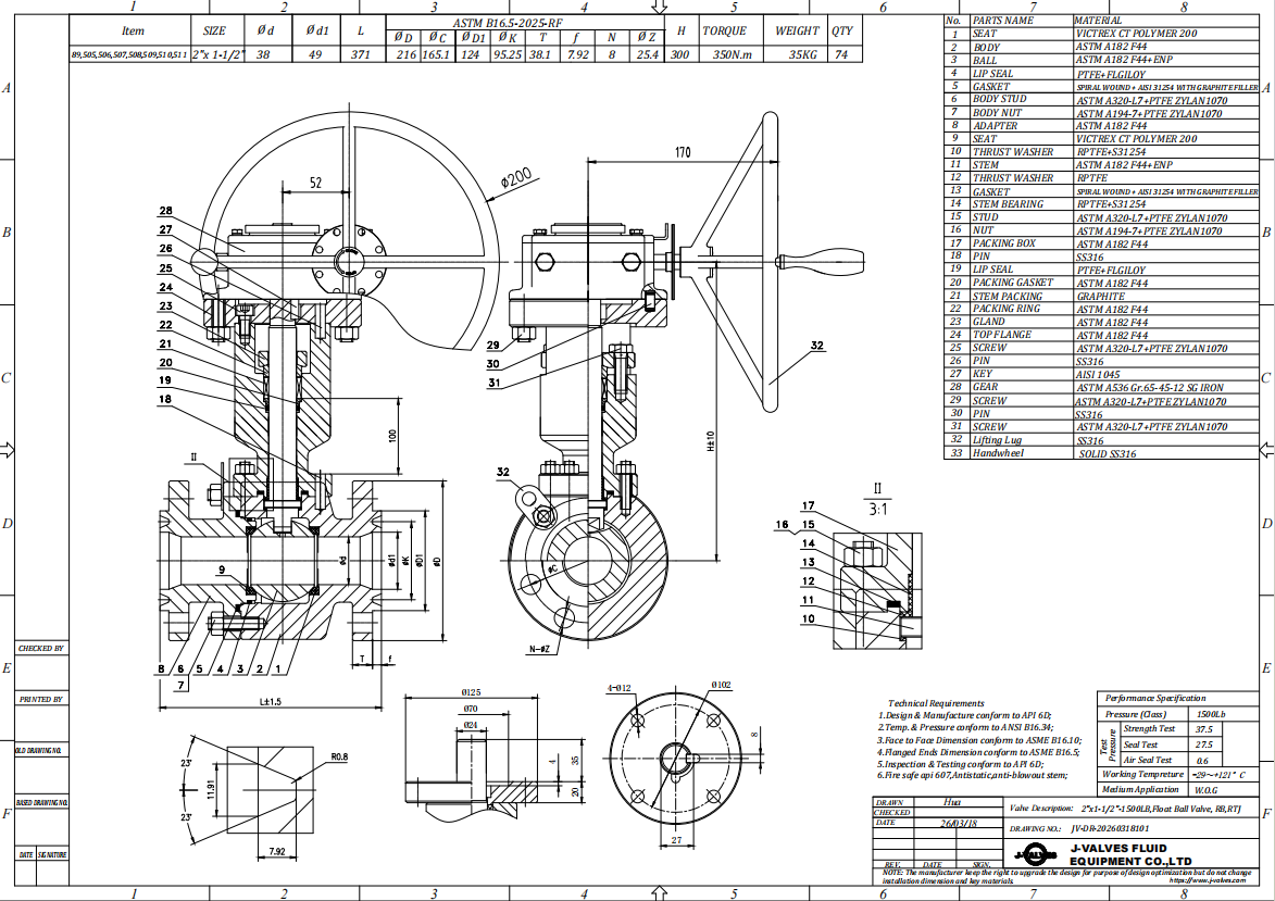
Material Options
The plate says F316, and A182 F316 is the forging specification behind it, so on this valve the stamped code can be read at face value. The one thing it cannot tell you is 316 against 316L. Both answer to the same family name, the difference is carbon, and carbon is not a stamped character. That question belongs to the EN 10204 3.1 certificate, and it should be asked before the order rather than after delivery.
F316 earns its place with molybdenum, around two to three percent, which is what lifts its resistance to pitting and crevice attack above 304 in chloride bearing service. It is a step and not a solution. The places where this valve will show chloride damage first are the crevices: under the body joint gasket, in the seat pocket, and at the stem where the packing sits. A 316 valve in warm chloride brine fails in a crevice long before it fails in the open bore.
The ball is inside the body and no photograph will settle its grade. The page offers F316 or CF8M, which are the wrought and the cast versions of the same alloy with different certificates, and hard chrome on top. Order the form the file requires and let the certificate carry it.
Packing and seats are where the temperature range is actually decided. PTFE packing and PTFE seats are the standard supply, and both are comfortable at the bottom of the range. At the top of the range printed on the page neither survives, and the honest description of a valve that does survive is a different valve: graphite packing, a metal seat, and a leakage class that is measured rather than zero.
| Component | Standard Material | Optional Upgrade | Service Notes |
|---|---|---|---|
| Body and end cap | ASTM A182 F316 forging, stamped F316 | A182 F316L | Plate code and certificate agree here |
| Body joint gasket | Spiral wound, graphite filler | PTFE filler for clean service | Single use, replaced at every break |
| Ball | F316 wrought or A351 CF8M casting, hard chrome | F316L | Not visible in any photograph, certificate governs |
| Ball seats | PTFE | RPTFE, PPL, metal seat | The seat sets the top of the range, not the shell |
| Stem | A182 F316, supplied in two pieces | 17-4PH | The coupling is the new interface, not the stem |
| Stem packing | PTFE | Flexible graphite | Runs at body temperature, under the column |
| Column and yoke | A182 F316 tube | Not wetted | Ask for them on the certificate as well |
Technical Specifications
Class 150 is a table value and not a conversion. In ASME B16.34 the austenitic group carries a lower room temperature rating than the carbon group for the same class: 275 psi against 285 psi at 100 F. An F316 body is therefore rated from the austenitic column, and the figure printed for a carbon steel valve of the same class does not transfer to it.
DN80x50 carries two sizes and only one of them is a connection. The flanges are three inch and they are what bolts to the pipe. The two inch figure is the bore, and what it buys is a smaller ball, a smaller seat and a lower operating torque for the same line size.
What it costs is permanent. The pipe cannot be reduced to match it, the pressure drop at that point is there for the life of the installation, and a line that may ever be pigged cannot use it, because the tool will not pass a two inch passage in a three inch line.
The printed range runs from -29 C to +425 C. Read it as the range in which the shell is rated, then ask which part sets the limit for the valve as supplied.
The cold end is not where a stainless body has a problem. At the hot end the packing and the seats fail first, and on this construction the packing sits at body temperature. So the top of the range is not available to a PTFE packed, PTFE seated valve. It is available to the same body with graphite packing and a metal seat, and that is a different order line.
Flow capacity is not on the plate and not in the product standard. Cv for a reduced bore valve depends on the bore, on the port geometry in the ball and on the seat design, and the only defensible answer is the one measured for the size being bought. Ask for it in writing if the line is sensitive to pressure drop, and do not take it from a table for a full bore valve of the same nominal size.
| Item | Value | Basis |
|---|---|---|
| Nominal size | 3 x 2 inch, DN80 x DN50 | Nameplate and drawing |
| Pressure class | Class 150, recorded as PN20 | Nameplate, API 6D clause 7.2 |
| Rating at 100 F | 275 psi, austenitic group | ASME B16.34 table value |
| Bore | Reduced, two inch passage | Second figure on the plate |
| Body | Two piece, one bolted joint | Construction |
| End connection | Flanged, NPS 3 Class 150 | Ordered to one flange standard |
| Flange drilling | 190.5 / 152.4 / 4 x 5/8 in, or 200 / 160 / 8 x M16 | B16.5 Class 150 against EN 1092-1 PN16 |
| Face to face | Per ASME B16.10 table | Value on the signed GA drawing |
| Stem seal position | In the bolted body cover | Photograph, open yoke |
| Column | Dry, not a pressure boundary | Photograph, coupling window |
| Operator | Lever with locking pin | Standard supply |
| Temperature | -29 C to +425 C | Shell range, seat and packing govern |
| Anti-static | 10 ohm or less, ball to body | API 608 |
| Design standard | ASME B16.34 and API 608 | Product standard for floating valves |
Standards and Compliance
This is the size where the flange sentence on the original page stops working. ASME B16.5 Class 150 at NPS 3 is a 190.5 mm flange on a 152.4 mm bolt circle with four 5/8 inch bolts. EN 1092-1 PN16 at DN80 is a 200 mm flange on a 160 mm circle with eight M16 bolts. Same nominal size, same nominal pressure, twice the hole count.
NPS 3 is also the last four bolt size in B16.5 at this class, because NPS 4 goes to eight. Writing ASME B16.5 or EN 1092-1 on one line item is therefore not a choice of reference. It is a choice between two flanges that cannot be re-drilled into each other, because the metric holes fall between the imperial ones.
PN20 is a code rather than a flange series. API 6D records Class 150 as PN20, which is why the nameplate and the API reference agree with each other. EN 1092-1 has no PN20, so a metric line orders PN16 and receives the eight hole flange. The rating is the same. The drilling is not.
API 608 is the product standard written for floating ball valves, and it is the one this valve belongs to. API 6D is the pipeline valve standard normally applied to trunnion designs, and it appears on the original page together with 6DSS, 6A PSL4 and a wellhead pressure range, none of which describes a flanged Class 150 floating valve. If a project does ask for 6D on a floating valve, treat it as a design change with the paperwork attached and get the supplier to confirm in writing what changes.
| Requirement | Standard | What It Covers |
|---|---|---|
| Shell wall and rating | ASME B16.34 | Wall thickness and the pressure temperature table |
| Product standard | API 608 | Floating ball design, marking, anti-static |
| Pressure testing | API 598 | Shell and seat test, duration and acceptance |
| Flanges | ASME B16.5 or EN 1092-1 | Drilling and facing, imperially or metrically |
| Face to face | ASME B16.10 | End to end for the valve type and class |
| Fire safe | API 607, ISO 10497 | A certificate, when the project asks for one |
| Material certificate | EN 10204 3.1 | Heat identity and chemistry, carbon included |
| Surface condition | ASTM A380 | Passivation after machining |
Manufacturing Process
An A182 F316 body starts as a forging, is solution annealed and then machined. The joint faces on a two piece body are the pair that has to close on a gasket, so they are machined and then match marked, and the two halves stay together from that point. Studs are not a substitute for flat faces: a joint that has to be pulled shut by its bolts will weep after the first thermal cycle.
The ball is ground and plated, and the seats are machined after the ball is finished rather than to a nominal diameter. On a floating valve the low pressure seal comes from the interference between seat and ball, and interference set from a drawing rather than from the part in hand is the reason some valves weep at low pressure and hold at high pressure.
The column is a tube with a yoke and a top plate, and the two stem halves are joined inside it. Assembly checks the upper stem for runout and for freedom at the top plate, because a column that is not square to the body pulls the stem against its bore, and the fault shows up as a stiff quarter turn rather than as a bad part. The coupling is then keyed or clamped and the lever fitted.
Stainless is not automatically clean. A body machined on equipment that also cuts carbon steel can carry free iron on its surface, and free iron rusts. On a lagged line that rust is read as a corroding body, and the argument that follows is expensive. The routine answer is a passivation step to ASTM A380 after machining and before assembly, and a ferroxyl test where the project asks for evidence that it worked.

Quality Control and Testing
Two pressure tests and one electrical test carry most of the weight. The shell test is at 1.5 times the rating and covers the body, the body joint and the cover joint. The seat test is at 1.1 times and is run on both seats in both directions, at zero visible leakage because the seats are soft. The third is continuity, and on this valve it is the one that gets skipped.
API 608 requires an anti-static path from the ball through the stem to the body, and the acceptance is ten ohms or less. On a two piece stem that path crosses the coupling, which is one more interface than a standard valve has. The test therefore has to be taken between the ball and the body flange, not between the lever and the body, because a reading taken at the lever proves the upper stem and nothing below it. If the valve ships with the column separate, the test is repeated after assembly.
The dimensional check that fails most often in practice is the flange drilling, because the same valve can be ordered to two standards and the shop holds both drawings. It deserves its own line on the inspection record: standard, nominal size, class, hole count and bolt size, checked against the purchase order rather than against the drawing set.
Material identification covers the wetted parts and the certificate, and it should also cover the parts nobody thinks of. The column, the yoke and the top plate are not wetted, which makes them the parts most likely to be made from whatever bar was on the rack. On a stainless valve in a coastal or chemical site, a carbon steel yoke is a rust stain in the first wet season and a complaint in the second.
| Check | Method | Acceptance |
|---|---|---|
| Shell test | Hydrostatic at 1.5 times rating | No leakage at body, joint or cover |
| Seat test | Both seats, both directions, 1.1 times | Zero visible leakage, soft seat |
| Anti-static | Resistance, ball to body flange | 10 ohm or less |
| Packing | Gland take up before the column is fitted | No leakage at the stem in the shell test |
| Flange drilling | Against the purchase order | Hole count and bolt size as ordered |
| Material identity | Certificate and PMI on body, ball, stem, column | Grades as ordered |
| Marking | Nameplate against API 608 | Size, class, grade, heat and maker |
| Function | Quarter turn, lever arc, locking pin | Free travel, no binding at the top plate |

Applications and Industry Service
Heat transfer oil and hot process lines are where the distinction on this page matters most. If the insulation is there for energy, the valve works: the hand is outside the cladding and the line is turned without cutting the lagging. If the insulation is there because the fluid runs above the limit of the packing, this valve does not solve the problem, because the packing is not the part that moved. That job needs the gland at the top, which means the wet column.
District heating and substation pipework use the same valve for a plainer reason: the operator sits at a comfortable height above a buried or lagged main, and the quarter turn can be made with a glove on. Nothing in that duty asks the packing to run cool.
Chilled water and glycol invert the picture. The column becomes a cold finger, because the upper stem is cooled by conduction from the body, so frost forms at the top plate and around the lever while the packing stays cold down at the body. Frost at the top is an operating nuisance, a stiff lever and a hand that cannot grip, rather than a sealing fault. Insulating the column and sealing its penetration through the vapour barrier fixes the frost. It does not change where the seal is.
Chemical and food lines take the stainless body as the minimum and gain from a bore that can be cleaned. Chloride bearing products are the exception, and they are the reason to look at a super austenitic grade rather than at 316 in a thicker wall.
Three duties belong on another page. A line that will be pigged needs full bore, whatever the torque penalty. A service above the seat limit needs a metal seat and the leakage class that comes with it. A buried line needs a construction designed for burial rather than a column long enough to reach the surface.
Installation, Operation and Maintenance
Test before the insulation goes on. The body joint and the cover joint are both pressure boundaries, and both will be under the cladding for the life of the line. Once the lagging is closed, a weep at either one has nowhere to show except as damp insulation. A pressure test at the flange faces, a record of the joint and a photograph of the finished valve before cladding cost an hour and settle the question permanently.
Align on the flanges and not on the bore. The two inch passage inside a three inch body invites a fitter to line the pipe up against the bore, and the pipe is three inch. Bolt holes and flange faces set the alignment; the bore follows.
The quarter turn needs its arc clear of the cladding, and the locking pin needs to be reachable without removing anything. Both are layout decisions. A lever that fouls the insulation by a few degrees will be forced, and a forced lever on a two piece stem loads the coupling rather than the ball.
An actuator can be fitted, and on a two piece stem it adds two interfaces to the motion. For open and shut duty that is of no consequence. For anything that modulates, the lost motion in the coupling and the wind up in a long upper stem are both inside the control loop, and a floating ball valve with a soft seat is the wrong starting point for modulating service in any case.
Seat and ball access is through the end cap, which means the line is isolated, drained and the joint broken, and the gasket is single use. The packing is reached from above and the column comes off first, so a packing job is planned rather than improvised. None of that is unusual on a two piece valve. It is simply worth knowing before the cladding is closed.
How to Specify and Order
A short enquiry produces a correct valve, and these are the lines that decide it in the order a supplier needs them.
Start with the line: size, medium, operating temperature and pressure, and whether the pipe is imperial or metric, because that decides four holes or eight. State the bore as reduced and confirm that the line will never be pigged. Give the body grade and ask for the 3.1 certificate with the carbon level shown, so that the 316 against 316L question is answered on paper. Then state the seal requirement in the only words that matter: does the gland have to run near ambient temperature.
If the answer is yes, this is not the valve, and the enquiry should say wet column or extended bonnet and give the insulation thickness so that the height can be set on the drawing. If the answer is no, give the insulation thickness anyway, because the column height is fixed at order from the cladding and the clearance the operator needs, and it is not a catalogue length. Name the packing material separately from the seat material, because they do not always fail at the same temperature.
Finally, name the tests. Shell and seat to API 598 are routine. Continuity between ball and body at ten ohms or less is routine and should be on the record with the test point stated. Fire safe to API 607 or ISO 10497 is a certificate and not a claim, so if the project needs it, ask for the certificate with the valve rather than after it. Cv, where the line is sensitive, is a measured value for the size ordered.
One line in the purchase order prevents most of the arguments this page has been about: state whether the column is a dry column with the packing at the body, or a wet column with the gland at the top. The two look similar in a photograph and behave nothing alike on a hot line.
FAQ
Q: Is the stem seal above the insulation on this valve?
A: No. The photograph shows the stem in two pieces with a clamp coupling in an open yoke below the top plate, and an open yoke cannot hold pressure. The seal therefore sits at the bottom, in the cover bolted to the body, and it runs at body temperature. The column raises the operator, which is what a lagged line needs for access, and it does not move the packing out of the heat. If the packing has to run near ambient, order a wet column with the gland at the top, which is a different construction with the column inside the pressure boundary.
Q: Why does the same DN80 Class 150 flange come with four holes or eight?
A: Because the two standards are not the same flange. ASME B16.5 Class 150 at NPS 3 is four 5/8 inch bolts on a 152.4 mm circle in a 190.5 mm flange. EN 1092-1 PN16 at DN80 is eight M16 bolts on a 160 mm circle in a 200 mm flange. Nominal size and nominal pressure match and nothing else does, so a valve cannot be drilled for both and the metric holes cannot be added to the imperial pattern. NPS 3 is the last four bolt size in B16.5 at this class, which is why the difference appears here and not two sizes down.
Q: Can this valve be used on a line that may be pigged?
A: No. A reduced bore valve has a two inch passage inside a three inch body, and a pig sized for the line will not pass it. The reduced bore also leaves a permanent pressure drop at that point, and neither the bore nor the drop can be changed later without changing the valve. If pigging is possible at any point in the life of the line, specify full bore and accept the higher torque and cost.
Q: What does PN20 mean on the nameplate?
A: PN20 is the code API 6D uses for Class 150, so it describes the rating and not a pressure in bar. It is not an EN flange step either: EN 1092-1 runs from PN6 to PN100 without a PN20, so a metric line orders PN16 and receives a different drilling. Treat PN20 as a cross reference to Class 150 and order the flange to whichever standard the pipe is built to.


Hot Products


News
Ball Valves in A Kraft Pulp Mill: Black Liquor, Green Liquor And The Cost of Choosing The Alloy by Habit
White liquor at pH 14 cracks carbon steel welds, black liquor sets solid below 100 C, green liquor dregs grind seats: alloy choice and torque in a kraft mill.
Read More
Slug Flow And Ball Valves: What Actually Arrives At The Seat
A slug is liquid mass with momentum, not a pressure spike. What changes at the seat, in the cavity and at the actuator when liquid reaches a ball valve.
Read More
Ball Valves in Direct Lithium Extraction: PH 1 Eluate, Gypsum Scale And 438,000 Cycles in Twenty-Five Years
Direct lithium extraction swings valves from pH 1 eluate to pH 12 caustic, 48 column switches a day and gypsum scale. Materials, seats and torque.
Read More
Ball Valves in Geothermal Brine: Silica Scale, Chloride Cracking And The Cooling Trap
Why geothermal brine destroys ball valves: retrograde silica scale, calcite at the flash point, chloride cracking above 60 C and the 250 C seat limit.
Read More