


CHINA J-VALVES Offers Various High-quality I ndustrial Ball Valves
J-VALVES, a distinguished professional ball valve manufacturer rooted in China, takes pride in its extensive product portfolio. Our offerings span a wide range, including trunnion-mounted ball valves, floating ball valves, high-temperature ball valves, high-pressure ball valves, metal-sealed ball valves, ultra-low temperature ball valves, DBB ball valves, Three-way And Four-way Ball Valve, and fully welded ball valves. Each product is a testament to our commitment to precision engineering and reliable performance. Meticulously crafted, they are designed to not only meet but exceed the most stringent industrial demands, ensuring stable operation even under extreme conditions. This enables us to provide our clients with high-value services and makes our valves widely sought-after in industries.
Product Category
Contact Us


-
J-VALVES-Q41F
-
J-VALVES
Overview of the J-VALVES DN50 x DN40 PN20 Extended Stem Floating Ball Valve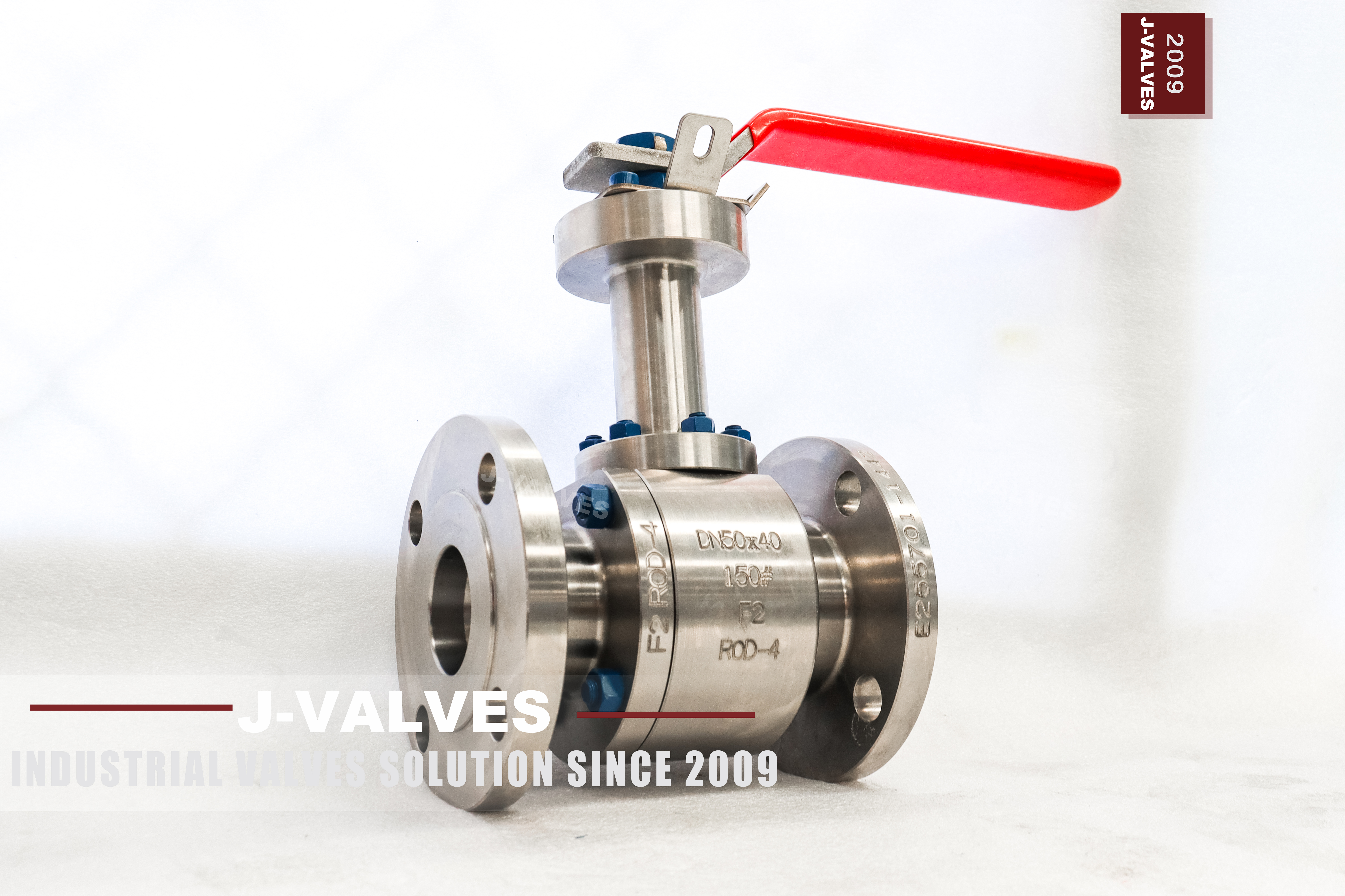
This is a DN50 two-piece floating ball valve with a 40 mm bore, a forged stainless body whose nameplate reads F2, a Class 150 rating that API 6D records as PN20, and a stem long enough to put the gland above the lagging. Its height is fixed at order, from the insulation and the clearance the operator needs.
On a lagged line the valve is the one item that still has to be reached. A standard valve buries its gland under the cladding: the packing runs at pipe temperature, the operator sits inside the insulation, and the lagging is cut away around the lever. An extension solves this, but only when it is part of the pressure boundary rather than a sleeve bolted on top.
Service is usually hot oil and heat transfer lines, district heating pipework, insulated chemical and food lines where the body has to be a stainless one, and chilled water loops where the problem is condensation on the gland. The 40 mm bore in a DN50 body suits branch, bypass and drain lines.
Three things it is not. Not a jacketed valve, which heats the body cavity and is the answer when the medium solidifies. Not a cryogenic bonnet, a longer neck with its own rules. And not a trunnion valve, so no trunnion language belongs here.
Design and Construction
The body is in two pieces: a main body and one bolted end cap. A ball valve has no bonnet, that part belongs to gate and globe valves, so the list is body, end cap, ball, two seats, stem, gland. The single joint carries a spiral wound gasket with graphite filler, and the end cap holds one seat.
Floating means the ball is not carried on trunnions. Line pressure pushes it into the downstream seat, each seat has its own springs, and the ball is free to move by what the seats allow. That freedom gives the cavity behaviour: when trapped liquid expands and cavity pressure rises, the ball lifts off the upstream seat and relieves upstream. Self relief by construction, so no piston effect seats, no injection ports, no cavity relief valve.
Count the openings through the pressure boundary and there are three: the body joint, the stem bore, the drain plug. A trunnion valve adds seat injection ports and bearing housings, which is the argument for a floating valve at Class 150.
The bore is 40 mm in a DN50 body, one nominal size down, which is what reduced bore means at this size. Only the ball, seats and cavity change; flanges, face to face and the operator mounting stay DN50. A DN50 pig will not pass a 40 mm bore, and the valve cannot be converted to full bore later.
The extension is where this valve differs, and the vocabulary is worth fixing. An extended stem runs a long stem through the lagging with the packing at the top, so the sealing element sits outside the insulation. A stem extension bolts a sleeve over the gland of a standard valve and raises only the operator. A lagged line needs the first.
Length changes three things. A long stem is a torsion bar, so it is machined from a larger section. The neck needs a guide bush near its base or the stem whips under torque. And operator weight plus lever pull load the neck in bending, so a long extension gets a bracket that clamps the neck housing, never the stem.
Material Options
The nameplate is a four line stamp, and one of those lines is the material: DN50x40, 150#, F2, POD-4. On every face the photograph shows, F2 is the only material designation, and no ASTM grade is stamped anywhere. That is not an omission, it is how the house coding works.
F2 is a J-VALVES catalogue code. It appears in no ASTM table, no EN table and no UNS list, so it cannot be looked up against a grade, and it must not be read as one. The grade behind the code lives on the EN 10204 3.1 certificate that travels with the heat, and that certificate is what a corrosion engineer should read before the valve goes on a chloride line. A stamp on the body is a claim by the foundry; the certificate is a claim by the mill, and only the second one is auditable.
There is a practical consequence at quotation stage, and it is a useful one. The class is on the valve, so the pressure answer needs no certificate: a Class 150 stainless body is read from the austenitic group of ASME B16.34, 275 psi at 100 F, against 285 psi for the carbon group. The corrosion answer is the opposite case, because the grade behind the code is exactly what decides it — 304 and 316 share that rating column and behave nothing alike on chlorides. One answer survives an unread certificate. The other does not.
The ball and the stem are inside the body, so no photograph shows them either. Both are certified on the same document as the body, and where a project file requires a wrought ball rather than a cast one, that is a line on the order rather than something the plate will tell you on arrival. Packing is PTFE or flexible graphite, and graphite is the one for hot oil, because it keeps the gland sealing after the soft parts have burned.
| Component | Standard Material | Optional Upgrade | Service Notes |
|---|---|---|---|
| Body and end cap | F2, forged stainless, catalogue code | A named grade, quoted as its own line | The plate carries the code, the certificate the grade |
| Body joint gasket | Spiral wound, graphite filler | PTFE filled for clean service | Graphite is the fire safe path |
| Ball | Grade stated on the 3.1 certificate, hard chrome | Wrought ball specified at order | Plating follows lapping, or a bare band appears |
| Ball seats | PTFE | RPTFE, PPL | The seat caps the temperature, not the body |
| Stem and extension | Same code as the body, certified with the heat | 17-4PH where the extension is long | A long stem is a torsion bar |
| Extended neck | Integral with the forged body | Full penetration welded neck | Pressure boundary, sees the shell test |
| Anti static | Spring loaded plunger, ball to stem to body | None required | A soft seat insulates the ball |
| Body bolts | A193 B8 with A194 8 nuts | B8M | B7 studs become the weak point |
| Flange facing | Raised face to ASME B16.5 Class 150 | EN 1092-1 PN16, separate body | The two drillings do not interchange |
| Operator | Lever with a locking hole | Worm gear or actuator on ISO 5211 | The lever arc must clear the cladding |
Technical Specifications
Read the pressure column with care, because three things answer to PN20. PN20 is the code API 6D clause 7.2 gives Class 150, and it belongs on the nameplate. It is not 20 bar, and it is not an EN flange step: the rating behind the code is read from the B16.34 table, not from the number in the name.
| Item | Value |
|---|---|
| Size | DN50 body, DN40 bore, 2 inch by 1.5 inch, reduced bore |
| Pressure class | Class 150, recorded as PN20 in API 6D clause 7.2 |
| Rating at 100 F | 275 psi, austenitic group 2.2 of ASME B16.34 |
| Body material | F2, forged stainless, catalogue code as stamped |
| Body style | Two piece, one bolted end cap |
| End connection | B16.5 Class 150 raised face, or EN 1092-1 PN16 as a separate body |
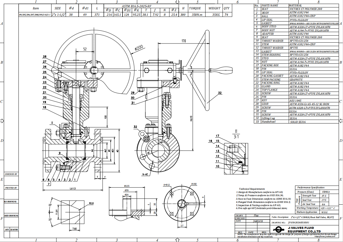
| Face to face | ASME B16.10, confirmed on the signed general arrangement drawing |
| Extension height | Fixed at order from the insulation and operator clearance |
| Stem sealing | Gland at the top of the neck, outside the lagging |
| Seat material | PTFE standard, RPTFE or PPL on request |
| Temperature, seat | The governing limit, below the body figure |
| Temperature, body | Austenitic group 2.2, flange ratings listed to 1000 F and 538 C |
Standards and Compliance
The product standard here is API 608, not API 6D. API 608 covers flanged, threaded and welded general service ball valves, it is the document requiring anti static construction and fire testing, and this valve sits inside its scope. API 6D is a pipeline standard and appears for one clause, 7.2, which supplies the PN code. The two should not share a data sheet, because 6D pressurises the cavity and checks both seats at once.
API 598 fixes the test pressures, shell at 1.5 times the rating and seat at 1.1 times, and deliberately does not fix one acceptance figure. On a soft seat the acceptance is zero visible leakage on both seats for the whole holding period; on a metal seat the standard gives a rate by size. So API 598 alone does not state how tight a valve is, and 598 plus zero leakage is a soft seat order.
The flange paragraph is the one to read twice. At DN50 the two systems come closest and still do not interchange. ASME B16.5 Class 150 on NPS 2 is 152.4 mm outside diameter, 120.7 mm bolt circle, four 5/8 inch bolts. EN 1092-1 PN16 on DN50 is 165 mm outside diameter, 125 mm bolt circle, four M16. Both are four bolt flanges, one inch thread and one metric, and the bolt circles differ. EN 1092-1 has no PN20 step, so a European buyer drops to PN16, and that is a different body.
Temperature is a two layer question. The body is austenitic group 2.2 and its flange ratings are listed to 1000 F, which is 538 C. The seat is far lower: PTFE is offered to about 200 C, and PPL is quoted to 280 C rather than the 260 C that belongs to PEEK. The valve sells on the lower of the two, so the 425 C on the original sheet is a carbon steel habit.
| Requirement | Standard | What J-VALVES Supplies |
|---|---|---|
| Pressure and temperature rating | ASME B16.34, group 2.2 | 275 psi at 100 F, falling with temperature |
| Product standard | API 608 | Anti static, fire tested, marked |
| PN designation | API 6D clause 7.2 | PN20 on the nameplate of a Class 150 valve |
| Flanges | ASME B16.5 Class 150 | Or EN 1092-1 PN16, as a separate body |
| Face to face | ASME B16.10 | Confirmed on the general arrangement drawing |
| Shell test | API 598 | 1.5 times the rating, no leakage |
| Seat test | API 598 | 1.1 times, zero visible leakage on a soft seat |
| Fire test | API 607 and ISO 10497 | Certificate covering the sizes supplied |
| Material certificate | EN 10204 3.1 | Heat numbers for body, ball and stem |
Manufacturing Process
The body and the end cap are forged, then machined as a pair and match marked, so the joint faces and bolt holes are a matched set. That matters more here than on a standard valve, because the neck is machined after the body, and a body paired with another end cap would join two faces never lapped together.
Where the design allows, the neck is forged integral with the body. Where it is welded, it is a full penetration weld, it is inspected, and the neck bore is line bored afterwards so the stem runs true over its whole length. The neck is pressure boundary and sees the shell test with the body.
The ball is machined, lapped to a sphere and then hard chrome plated. Plating follows lapping, because grinding a plated ball would leave an unplated band exactly at the seat contact line, and that band is where a chrome ball starts to pit.
Seats are machined from virgin PTFE and matched to the ball actually fitted rather than to a nominal diameter, so the interference is set by measurement. Assembly ends with the gland packed at the top of the neck, the extension fitted and the valve stroked, then marked and crated with the neck braced.

Quality Control and Testing
Every valve carries its heat number from the mill certificate to the nameplate, and the checks below are recorded against it.
| Step | What Is Checked | Standard or Acceptance |
|---|---|---|
| Incoming material | Heat number against the 3.1 certificate, chemistry | EN 10204 3.1 |
| Material identification | Alloy identity of body, ball and stem | No mix up between the grades behind neighbouring codes |
| Machining | Joint faces, bolt circle, bore, neck squareness | General arrangement drawing |
| Ball and seat | Sphericity, finish, chrome coverage on a coupon | No unplated band at seat contact |
| Shell test | Body, joint, neck weld, packing | API 598, 1.5 times, no leakage |
| Seat test | Both seats, both directions | API 598, 1.1 times, zero visible leakage |
| Function | Quarter turn, lever arc, locking hole, gland take up | Drawing and order |
| Marking and paperwork | Nameplate, anti static continuity, 3.1 file | API 608 marking |

Applications and Industry Service
Heat transfer and hot oil loops are the classic case. The medium runs hot enough that a gland at pipe temperature would cook a PTFE packing, and the line is lagged for energy rather than for frost, so the extension keeps the packing inside its own range while the body stays at line temperature.
District heating and substation pipework use the same valve for another reason: the operator has to be reachable through a dense layer of cladding, and a lever buried in mineral wool is not an operator. The standard grade is the right one on treated water, and the order steps up where chlorides are present.
Insulated chemical and food lines take the stainless body as the minimum, and the extension lets the packing be adjusted without stripping the insulation. Chilled water and glycol loops invert the problem: the gland is cold, condensation forms on it, and the extension lifts the packing into warmer air.
Three duties belong elsewhere. Steam above the seat limit takes the PTFE out whatever the body grade. A line that may be pigged cannot use a 40 mm bore. And a medium that solidifies at ambient needs a jacket, which is a different valve rather than a longer stem.
Installation, Operation and Maintenance
Stem up is the natural position for an extended stem valve and the one the neck was designed for. A horizontal stem on a long extension hangs the operator weight sideways off the neck, and every turn of the lever adds to that load. If the pipe will not allow a vertical stem, say so at order.
The support, where one is used, clamps the neck housing and never the stem, because a clamp on the stem turns the extension into a bearing surface. Above the support the cladding needs a collar sealed around the neck. Corrosion under insulation is what takes stainless valves off lagged lines: water soaks the insulation, chlorides concentrate against the hot metal, and the body cracks outside while the bore is still clean.
Operation is a quarter turn, and a soft seated valve is an isolation valve. Throttling a PTFE seat at part open erodes it, and the damage does not show until the valve is asked to hold.
The gland can be adjusted with the line live, and that is the only task that does not need isolation. Replacing the packing, or reaching the ball and seats, needs the line isolated and the end cap removed, because the body joint is a pressure boundary like any other.
How to Specify and Order
Five answers make the quotation exact. The bore: 40 mm through a DN50 body, or full bore, decided before the order. The flange: B16.5 Class 150 or EN 1092-1 PN16, one of the two, because they are different bodies. The insulation thickness and the height from the pipe centre line to the top of the neck. The operator, with the lever arc checked against the cladding. And the seat with its temperature.
On the paperwork, ask for the 3.1 certificate with heat numbers for body, ball and stem, the shell and seat test records, the fire certificate with its size range, and the general arrangement drawing that fixes the extension height. The drawing defines this valve; everything else describes a family.
FAQ
Q: Can this valve be bolted to an EN PN16 flange?
A: No, and the two are easy to confuse because both are four bolt flanges at this size. EN 1092-1 has no PN20 step, so a European line takes PN16, and PN16 on DN50 has a different outside diameter, a different bolt circle and metric bolts where the American flange has inch bolts. PN20 on the nameplate describes the Class 150 rating, not a flange you can buy. Order the body to the flange that is actually on the pipe.
Q: Is an extended stem the same as a jacketed valve?
A: No. A jacket is a chamber around the body carrying steam or hot oil, and it exists to keep the medium from solidifying; it does nothing for the operator. An extended stem moves the packing and the operator out of the insulation, and it does nothing for the medium. A line that needs both needs a jacketed valve with an extended stem, and that is quoted as a special.
Q: Can the extension be shortened on site, or added later?
A: Neither. The neck is part of the pressure boundary and is shell tested with the body, so cutting it or adding a sleeve after despatch leaves a pressure part that was never tested and a gland that no longer sits square. The height is fixed at order from the insulation thickness and the clearance the operator needs. A change of insulation later means a new neck, so measure the finished lagging before ordering.
Q: Why does the data sheet say 425 C when the valve cannot go that high?
A: Because 425 C is the carbon steel figure that gets copied from sheet to sheet. This body is austenitic group 2.2, whose flange ratings are listed to 1000 F, but the seat decides the valve: PTFE is offered to about 200 C and PPL to 280 C. On a soft seated valve the temperature is the lower of the two, so the honest figure is the seat figure, and it is quoted with the valve.


Hot Products


News
Ball Valves in A Kraft Pulp Mill: Black Liquor, Green Liquor And The Cost of Choosing The Alloy by Habit
White liquor at pH 14 cracks carbon steel welds, black liquor sets solid below 100 C, green liquor dregs grind seats: alloy choice and torque in a kraft mill.
Read More
Slug Flow And Ball Valves: What Actually Arrives At The Seat
A slug is liquid mass with momentum, not a pressure spike. What changes at the seat, in the cavity and at the actuator when liquid reaches a ball valve.
Read More
Ball Valves in Direct Lithium Extraction: PH 1 Eluate, Gypsum Scale And 438,000 Cycles in Twenty-Five Years
Direct lithium extraction swings valves from pH 1 eluate to pH 12 caustic, 48 column switches a day and gypsum scale. Materials, seats and torque.
Read More
Ball Valves in Geothermal Brine: Silica Scale, Chloride Cracking And The Cooling Trap
Why geothermal brine destroys ball valves: retrograde silica scale, calcite at the flash point, chloride cracking above 60 C and the 250 C seat limit.
Read More