


CHINA J-VALVES Offers Various High-quality I ndustrial Ball Valves
J-VALVES, a distinguished professional ball valve manufacturer rooted in China, takes pride in its extensive product portfolio. Our offerings span a wide range, including trunnion-mounted ball valves, floating ball valves, high-temperature ball valves, high-pressure ball valves, metal-sealed ball valves, ultra-low temperature ball valves, DBB ball valves, Three-way And Four-way Ball Valve, and fully welded ball valves. Each product is a testament to our commitment to precision engineering and reliable performance. Meticulously crafted, they are designed to not only meet but exceed the most stringent industrial demands, ensuring stable operation even under extreme conditions. This enables us to provide our clients with high-value services and makes our valves widely sought-after in industries.
Product Category
Contact Us


-
J-VALVES-Q41F
-
J-VALVES
Overview of the J-VALVES 6 Inch Class 300 WCB Two-Piece Floating Ball Valve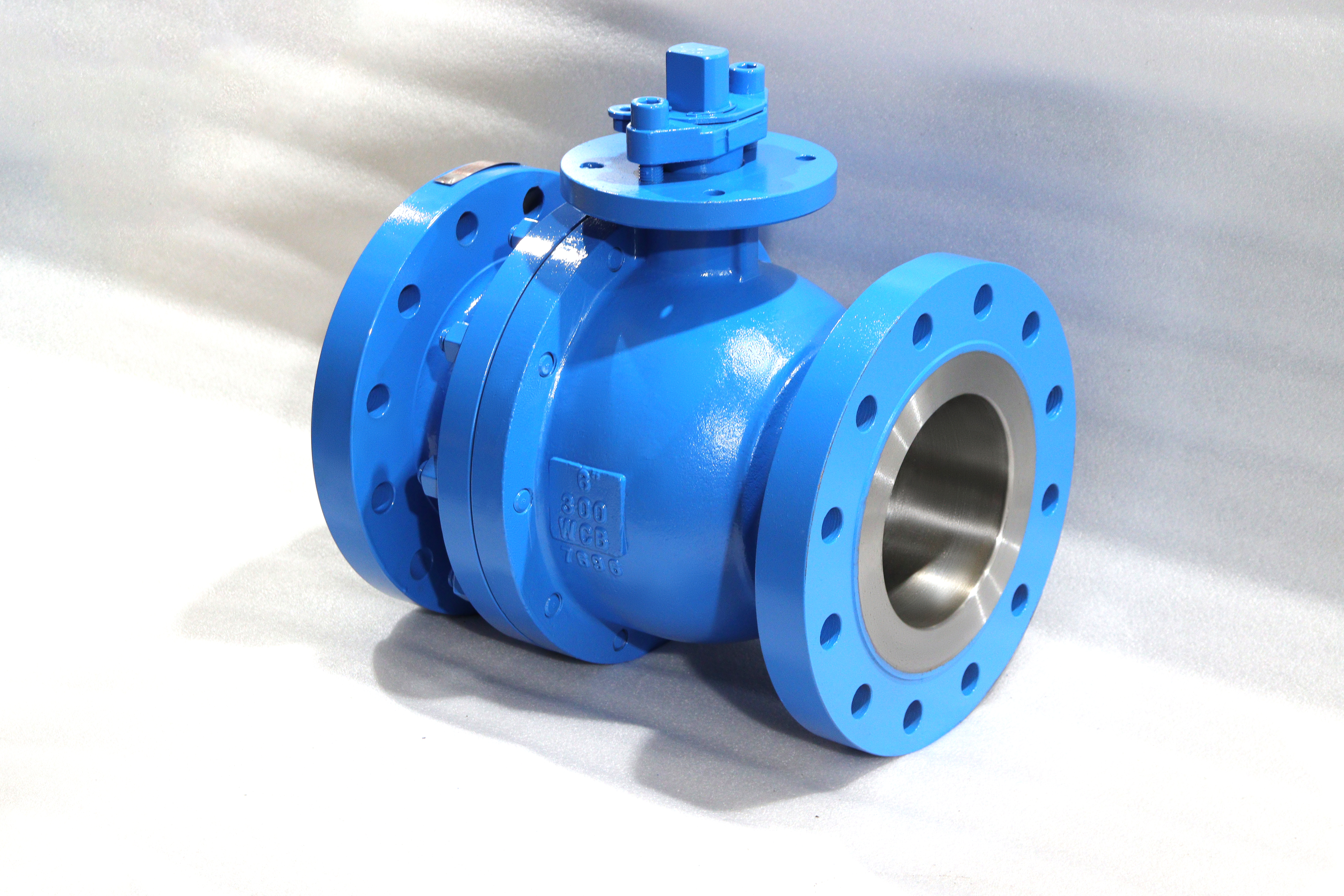
The J-VALVES 6 inch Class 300 floating ball valve is a cast carbon steel isolation valve: an ASTM A216 WCB body split into a main body and one bolted end cap, ASME B16.5 raised face flanges at both ends, a ball that floats on line pressure instead of turning on trunnions, and a soft seat that closes tight. Three fields on the data sheet stay open after the size and the class have been written: the bore, the finish on the ball, and the acceptance criterion at the seat. This page is about those three.
The structure follows the load. Seat load is line pressure multiplied by the area it acts on, so at this size a floating ball still seals comfortably, and the pressure that pushes it into the downstream seat is the pressure that makes the seal. A trunnion would add bearings, a second load path and parts that do no work at this duty. Two pieces rather than three because one bolted joint is enough to get ball and both seats in and out; the second joint of a three-piece body buys access through the line, not a better valve.
Most of these valves go into plant utility and product isolation: gas and compressed air headers, cooling water and firewater where a soft seat is accepted, hot oil inside the seat limit, tank farm and loading lines, and skid packages built around a six inch flange. The duty is open or shut, a few times a shift at most, and what the buyer needs is a flange that matches, a seat that does not weep after a year of standing pressure, and a valve that can be proved closed.
Design and Construction
The main body carries both seat pockets and the stem bore, while the end cap carries one seat ring and closes the bore. Both seats seal, so the valve holds in either direction, but only the end cap end is detachable, and the arrow on the body shows which. Fit the valve the way the arrow points. With the valve closed the joint then sees cavity pressure rather than full line pressure, and the joint is the one place where a two-piece body can leak to atmosphere.
The ball is not fixed in the body. It sits between two seat rings with a little room to move, and line pressure slides it onto the downstream seat. Two consequences follow, and both are advantages here. Liquid trapped in the cavity that expands pushes the ball off the upstream seat and vents back into the line, so the cavity is self-relieving and needs no external device. And because there is no piston face behind the seat, there is no seat injection port either: three pressure boundary penetrations that a trunnion valve carries are simply absent.
The stem is a separate part from the ball and only transmits torque. It is retained by the body, so it cannot be blown out, and a spring loaded pin bridges ball, stem and body to keep the assembly electrically continuous. That last detail matters on gas and on any line where static has to be drained. A soft seat insulates the ball from the body, so the conductive path has to be made deliberately and then measured on every valve rather than assumed from the drawing.

Material Options
The table is the build for this size and class. Two rows decide more than the rest. The seat sets the temperature the valve can be sold for, because the body outlives every soft compound in the list. And the ball row needs reading carefully, because the base metal and the finish are two different things: the ball is carbon steel, and the ENP on it is a coating rather than a grade of stainless.
| Component | Standard Material | Optional Upgrade | Service Notes |
|---|---|---|---|
| Body and end cap | ASTM A216 WCB, cast carbon steel | A105 forged; A350 LF2 for low temperature | Group 1.1 in ASME B16.34; A105 reads the same ratings |
| Ball | WCB or A105, ENP coated | Hard chrome; stainless overlay; stainless ball | The base metal is carbon steel, so the coating decides life |
| Stem | A105 with ENP | 17-4PH; SUS420 | 17-4PH held to 22 HRC where NACE applies |
| Seat | PTFE and RPTFE | PPL to 280 C; PEEK to 260 C; metal with flexible graphite to 425 C | The seat, not the body, is the valve temperature limit |
| Body joint gasket | Flexible graphite spiral wound | 316L winding | Has to survive the fire test; a PTFE sheet will not |
| Packing | Flexible graphite with Inconel wire | PTFE V-rings | Graphite for temperature, PTFE for cycle life |
| Bolting | ASTM A193 B7 with A194 2H nuts | B7M; B8M | B7M where sour service is specified |
| Anti-static | Spring loaded pin, ball to stem to body | None | Measured on every valve, not on a sample |
ENP is electroless nickel plating, deposited chemically rather than electrically, which is why it reaches the ball bore and the seat band evenly and why thickness stays uniform on a curved surface. What it is not is a material. Under the nickel sits WCB or A105, so a pore, a scratch or a thin patch is a small area of carbon steel exposed to the medium, and in chloride water that becomes a pitting site inside a much larger cathodic area. The inspection that matters is thickness, adhesion and porosity, and all three belong on the certificate, not in a verbal assurance.
Technical Specifications
The table is the data sheet for this size and class. Class 300 is written as the class; PN50 appears only as the cross reference that API 6D clause 7.2 gives it, and is not an EN flange step. The bore figure is the API 6D Table 1 minimum for a full bore NPS 6 valve in Class 300, not a measured port, and the reduced option is the other entry in the same table. Face to face follows ASME B16.10 for the pattern ordered and is confirmed on the signed drawing.
| Item | Value |
|---|---|
| Size | 6 inch, DN150 |
| Pressure class | Class 300 to ASME B16.5 |
| Cross reference | PN50, per API 6D clause 7.2 |
| Bore, full | 150.0 mm minimum, API 6D Table 1 |
| Bore, reduced | 100.0 mm minimum, 6x4 to API 6D Table 1 |
| Body material | ASTM A216 WCB |
| End connection | Flanged, raised face, ASME B16.5 NPS 6 Class 300 |
| Flange drilling | 317.5 mm outside diameter, 269.9 mm bolt circle, 12 bolts |
| Facing | Raised face, 215.9 mm face diameter |
| Face to face | ASME B16.10 for the pattern ordered; on the signed GA drawing |
| Operation | Lever with locking device; gear, pneumatic or electric on request |
| Design | ASME B16.34 wall thickness with API 608 |
| Pressure test | API 598, shell at 1.5 times, seat at 1.1 times |
| Fire test | API 607 and ISO 10497 |
Standards and Compliance
Two documents govern, and they do different jobs. ASME B16.34 sets the wall and the pressure temperature rating: WCB sits in group 1.1, where Class 300 allows 740 psi at 100 F, and the allowable falls as the temperature rises until the group ends at 425 C. API 608 is the product standard for a flanged metal ball valve, and it is where the anti-static requirement, the blowout proof stem and the test reference come from. API 6D is not the design basis here, although its clause 7.2 supplies the PN50 cross reference.
The seat test is where a data sheet most often says less than it means. API 598 applies the same pressure to both designs, 1.1 times the rating, but not the same acceptance. A soft seated valve has to hold with no visible leakage: no drops downstream, no bubbles under water, for the whole hold. A metal seated valve is allowed a rate from the standard's table, scaled by size, because metal cannot conform the way a polymer does. So the order line does not fix the criterion, and a buyer who writes API 598 with zero leakage is asking for a soft seat whether the seat column says so or not.
Three more references do real work. The shell test runs at 1.5 times the rating with the valve part open so that body and cavity are both exposed, and it accepts no leakage and no permanent distortion. Fire safety is a test result, not a design method, so API 607 and ISO 10497 belong in the certificate column. And the material certificate is EN 10204 3.1, with heat numbers that follow the casting into the test record.
| Requirement | Standard | What J-VALVES Supplies |
|---|---|---|
| Wall thickness and rating | ASME B16.34, group 1.1 | Cast wall checked against the table, rating read at design temperature |
| Product requirements | API 608 | Anti-static path, blowout proof stem, marking |
| Shell test | API 598 at 1.5 times | Every valve, no leakage, certificate by serial |
| Seat test, soft seat | API 598, zero visible leakage | Both directions at 1.1 times |
| Seat test, metal seat | API 598, tabulated allowance | Rate stated on the test record, not implied |
| Fire test | API 607 and ISO 10497 | Certificate per order |
| Material certificate | EN 10204 3.1 | Heat numbers traced to test record and nameplate |
| Flange dimensions | ASME B16.5 | Class 300 NPS 6, raised face |
Manufacturing Process
Body and end cap are cast from the same heat whenever the order allows, so the two halves of the joint share a chemistry and answer machining and temperature the same way. Joint faces are machined with the halves bolted together under a controlled load: the faces are cut as a pair and the stud holes drilled in line, then the joint is opened only for cleaning and gasket fitting. That single decision decides whether the valve still seals after it has been opened once in the field.
The ball starts as a casting or a forging, is machined, ground and lapped, and only then plated. Plating after lapping is the order that matters: a ball ground afterwards has an uncoated band exactly where the seat runs. ENP goes on in a bath, so the ball is fixtured to let the bore and the seat band see the same solution, and thickness is checked on a coupon from the same batch. Assembly is dry, with seat squeeze and gland load set to the build sheet and turning torque recorded before testing.

Quality Control and Testing
Eight checks stand between the casting and the crate. The first three cannot be corrected later: chemistry with heat traceability, casting soundness by visual and ultrasonic examination, and the machined geometry of flanges, joint faces and bore. The next two are about the coating and the fit: ENP thickness, adhesion and porosity, then ball roundness and seat squeeze. The last three are the pressure tests, the anti-static measurement and the marks, with the serial carried across the test record, the certificate and the nameplate.
| Step | What Is Checked | Standard or Acceptance |
|---|---|---|
| 1 | Chemistry and heat number | Certificate to the ordered grade, castings traceable |
| 2 | Casting soundness | Visual and ultrasonic, no injurious defect in the pressure boundary |
| 3 | Machining | Flange facing, joint flatness, bore, faces and holes in one set up where possible |
| 4 | Ball coating | ENP thickness, adhesion and porosity on a batch coupon |
| 5 | Ball and seat fit | Roundness, surface finish, seat squeeze to the build sheet |
| 6 | Shell test | API 598 at 1.5 times, no leakage, no distortion |
| 7 | Seat test | API 598 at 1.1 times, both directions, acceptance per seat type |
| 8 | Marking and documents | Size, class, material, heat number, serial, test record |

Applications and Industry Service
The natural work is isolation on plant utilities and product lines: gas and compressed air headers, cooling water and firewater where a soft seat is accepted, hot oil inside the seat limit, tank farm and loading arms, and skid packages built around a six inch flange. In all of these the valve is either open or shut, the medium is clean enough that the seat is not being cut, and the reason for buying it is a bore that passes the flow and a seat that holds.
It is worth being clear about where this valve is the wrong choice. A line that will be pigged cannot use the reduced bore version, because the 6x4 port is smaller than any tool sized to the pipe. A circuit that needs double block and bleed to prove two barriers needs a trunnion valve, not this one. A buried line needs a valve chamber, because the body joint has to stay reachable. And a medium that attacks carbon steel moves the whole discussion to a different body material rather than a different coating.
Installation, Operation and Maintenance
Fit the valve with the end cap downstream and the lever where an operator can reach it without fouling the adjacent flange. Support the body where the line is not otherwise anchored, particularly on a vertical run. Bring the studs up in a cross pattern in at least three passes, check that the faces are parallel before the last pass, and use a gasket made for the raised face, not a full face sheet cut to the outside diameter.
Operation is a quarter turn, and the lever has a locking device so the valve can be left in a set position. Nothing on a floating valve can be replaced with the line under pressure. The gland can be tightened in service, which is the only adjustment available, but the body joint and the seat rings sit inside the pressure boundary: the line has to be isolated, depressurised and drained before the end cap comes off. When it does, the gasket is replaced rather than reused.
How to Specify and Order
Seven lines settle an order, and three are the fields this page is about. Write the size and class as NPS 6 Class 300 to ASME B16.5 and add the facing, because the face is machined before anyone notices a mistake. State the bore, 150.0 mm full or 6x4 at 100.0 mm, at order: the bore changes the ball, the seats and the cavity, while the flange and the face to face length stay with the six inch body. Then name the seat compound against the real temperature, the ball finish against the medium, the operator and its mounting, and the test package.
That last point deserves its own sentence. The test standard is not a statement of tightness; it is a reference to a document that carries two answers. Say soft seat, zero visible leakage, if that is what the line needs, and expect a metal seat to be accepted against a tabulated rate. Writing the criterion down also settles the argument at witness testing, when the gauge is connected and nobody wants to read the standard for the first time. If the valve will later be motorised, say so at enquiry: the mounting flange and stem square are fixed before machining.
FAQ
Q: Does a 6 inch valve have a 6 inch bore?
A: Not necessarily, and the answer is written in API 6D Table 1 rather than in the size. A full bore NPS 6 valve in Class 150 to 600 has a minimum bore of 150.0 mm, and the reduced 6x4 entry in the same table is 100.0 mm. What does not change is the body: the ASME B16.5 flanges, the face to face length and the operator interface all stay with the six inch valve, because only the ball, the seats and the cavity follow the bore. That is why a 6x4 cannot be converted to full bore later, and why a line that will be pigged should not order it.
Q: Is the ENP ball stainless?
A: No. The ball is WCB or A105, both carbon steel, and ENP is electroless nickel plating on top of it. The nickel is what the seat runs against and what the medium sees, so thickness, adhesion and porosity are the numbers to ask for, measured on a coupon from the same bath. Where the water carries chlorides, or the medium attacks carbon steel, a coating is the wrong answer and the order should move to a stainless ball or a stainless overlay, which changes the trim rather than the body.
Q: What does API 598 actually require at the seat?
A: Two different things, because the standard carries two acceptance criteria. At 1.1 times the rating, a soft seated valve has to show no visible leakage: no drops on the downstream face and no bubbles under water for the whole hold. A metal seated valve is allowed a leakage rate from the table, scaled by size. So the standard quoted on a data sheet does not by itself say how tight the valve will be, and an order that wants zero leakage has to name a soft seat to get it.
Q: Can this valve give double block and bleed?
A: No, and the reason is structural rather than a missing option. The pressure that pushes the ball into the downstream seat is the same pressure that lifts it off the upstream seat, so there are never two independent barriers to prove. A double block and bleed test needs a valve where both seats hold with the cavity vented, which means a trunnion design with the right seat type. On this valve the cavity drain is for proving the valve is closed, not for proving two seats.


Hot Products


News
Ball Valves in A Kraft Pulp Mill: Black Liquor, Green Liquor And The Cost of Choosing The Alloy by Habit
White liquor at pH 14 cracks carbon steel welds, black liquor sets solid below 100 C, green liquor dregs grind seats: alloy choice and torque in a kraft mill.
Read More
Slug Flow And Ball Valves: What Actually Arrives At The Seat
A slug is liquid mass with momentum, not a pressure spike. What changes at the seat, in the cavity and at the actuator when liquid reaches a ball valve.
Read More
Ball Valves in Direct Lithium Extraction: PH 1 Eluate, Gypsum Scale And 438,000 Cycles in Twenty-Five Years
Direct lithium extraction swings valves from pH 1 eluate to pH 12 caustic, 48 column switches a day and gypsum scale. Materials, seats and torque.
Read More
Ball Valves in Geothermal Brine: Silica Scale, Chloride Cracking And The Cooling Trap
Why geothermal brine destroys ball valves: retrograde silica scale, calcite at the flash point, chloride cracking above 60 C and the 250 C seat limit.
Read More