


CHINA J-VALVES Offers Various High-quality I ndustrial Ball Valves
J-VALVES, a distinguished professional ball valve manufacturer rooted in China, takes pride in its extensive product portfolio. Our offerings span a wide range, including trunnion-mounted ball valves, floating ball valves, high-temperature ball valves, high-pressure ball valves, metal-sealed ball valves, ultra-low temperature ball valves, DBB ball valves, Three-way And Four-way Ball Valve, and fully welded ball valves. Each product is a testament to our commitment to precision engineering and reliable performance. Meticulously crafted, they are designed to not only meet but exceed the most stringent industrial demands, ensuring stable operation even under extreme conditions. This enables us to provide our clients with high-value services and makes our valves widely sought-after in industries.
Product Category
Contact Us


Pressure Rating: Class 150LB to 2500LB (PN20 to PN420)
Temperature Range: -29℃ to +425℃
Body / Side Body: ASTM A105 (carbon steel), A350 LF2 (low-temperature carbon steel), A182 F304/F316/F316L (stainless steel), F51/F53 (duplex stainless steel), Inconel (nickel-based alloy for special corrosive service)
Ball: F304/F316/F316L with ENP electroless nickel plating (standard) / Stellite (STL) alloy coating (for erosive service)
Stem: F316/F316L/17-4PH, high strength and corrosion resistant
Seat: RPTFE (standard) / nylon / PEEK / F316 with Stellite hardfacing (metal seal)
Packing: PTFE V-type combination / flexible graphite (high-temperature type)
Bolts: ASTM A193 B7/B7M/B8M (selected based on temperature and corrosive service)
Nuts: ASTM A194 2H/2HM/8M
Gasket: Stainless steel spiral-wound gasket / metal ring joint gasket (RTJ)
End Connection: Flanged (RF/RTJ) in accordance with ASME B16.5; butt weld ends (BW) or flange-weld combination available as options
Operation: Manual (lever / worm gear), pneumatic (double-acting / single-acting spring return), electric (on-off / modulating / intelligent type), hydraulic, pneumatic-hydraulic actuator (for emergency shutdown in long-distance pipelines)
Design Standards: API 6D, API 608, ASME B16.34
Test Standards: API 6D, API 598
Face-to-Face Dimensions: Conforms to ASME B16.10
-
J-VALVES-Q347F
-
J-VALVES
Overview of the J-VALVES API6D Three Piece Forged Steel Flange Trunnion Ball Valve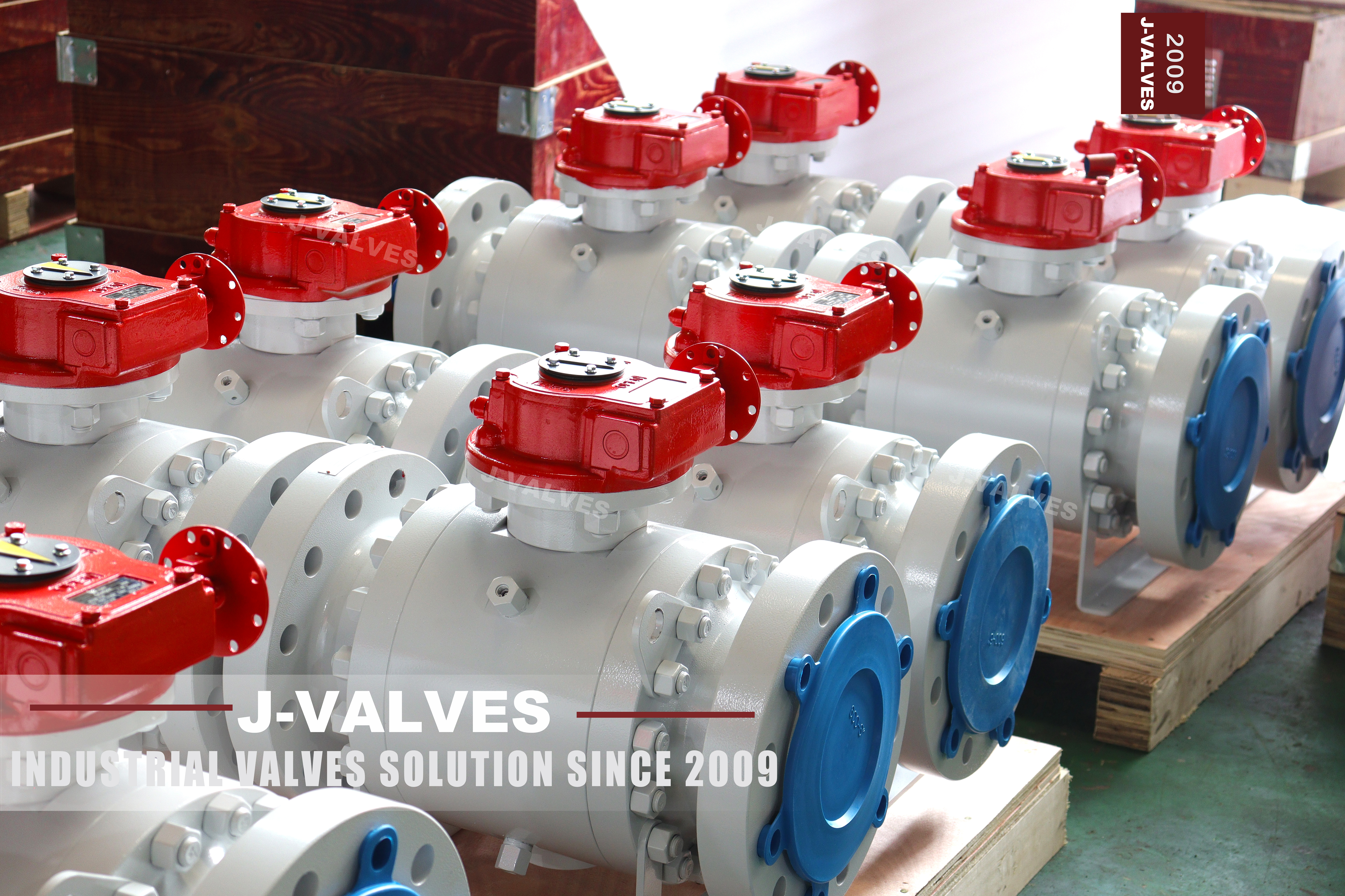
This is a range page rather than a single size: half an inch to fifty six inch, Class 150 to 2500, which API 6D writes as PN20 to PN420. The body is forged and split into three parts, the ball turns on an upper and a lower trunnion, and both ends are flanged to ASME B16.5 with either a raised face or a ring groove. Every size in that grid shares one architecture; what changes along the grid is the gasket, the seat, the operator and whether a forging of that size can be made at all.
The name on the page is API6D, and that is the standard the valve is bought against. The parameter block also lists API 608 and ASME B16.34, which is not wrong but is often read as if the three were interchangeable. They are not. One sets the pressure boundary, one sets what the valve has to do in a pipeline, and one is a general industrial standard that a pipeline project does not accept in place of the first.
Design and Construction
The three parts are a centre body and two side bodies, drawn together by studs and nuts. The centre body carries the ball, both seat rings and the trunnion bearings; the side bodies carry the flange and the end of the bore. Undo the studs and a side body comes away, which exposes one seat without disturbing the other. That is the whole reason the three piece pattern survives in pipeline service, where a two piece body would need the line split to reach the same seat.
The ball is not carried by the seats. It sits on a trunnion above and below, in metal backed bearings, so the pressure load goes into the body through the bearings and the seats only have to seal. That is why the torque of this valve barely moves as the pressure rises, and why a fifty six inch build can still be turned by a gearbox rather than by a bigger actuator.

Material Options
A105 is the default body grade: forged carbon steel, normalised, and the cheapest thing that will hold the pressure at ambient temperature. It is the right answer for water, oil, gas and steam up to the point where the medium turns corrosive or the site turns cold; then the body moves to A350 LF2 for low temperature, or to A182 F304, F316, F316L for process duty, or to F51 and F53 duplex where chlorides and stress corrosion are the issue.
Every one of those grades is a forging, not a casting, and that is a real constraint at the top of the size range: a fifty six inch body has to start as a billet big enough to be hollowed out, and not every mill will press one. Where a size cannot be forged economically the same drawing is quoted in cast CF8M instead, which is a different product with a different certificate.
| Component | Standard Material | Optional Upgrade | Service Notes |
|---|---|---|---|
| Body and side bodies | ASTM A105 forged carbon steel, normalised | A350 LF2, A182 F304 or F316, F51 or F53 duplex | three pieces, two bolted joints |
| Ball | A182 F304 with electroless nickel plating | F316, hard chrome, tungsten carbide, cobalt alloy hardfacing | carried on trunnions, ground and lapped |
| Trunnion and bearings | Surface hardened forged stem material | 17-4PH, nickel alloy | takes the pressure load off the seats |
| Stem | A182 F316 | F316L, 17-4PH | blowout proof, anti static, keyed to the ball |
| Seat ring | RPTFE | nylon, PEEK, F316 with cobalt alloy hardfacing | spring loaded, self relieving |
| Body gasket | Spiral wound stainless with graphite filler | ring type joint metal ring | new gasket at every joint opening |
| Packing | PTFE V-ring set | flexible graphite for high temperature | adjustable gland |
| Body studs and nuts | A193 B7 with A194 2H | B7M with 2HM, B8M with 8M | tightened in three passes |
| Operator | Lever or worm gear, set by the size and class | pneumatic, electric, hydraulic, pneumatic-hydraulic | mounting pad and stem top machined for actuation |
Technical Specifications
The envelope is one half to fifty six inch, Class 150 to 2500, three piece forged body, full or reduced bore, flanged RF or RTJ to ASME B16.5, face to face to ASME B16.10, lever or worm gear, tested to API 598 and API 6D. The table on this page states the declared limits; the drawing for the size and class ordered states the actual dimensions, because wall thickness and flange drilling both change with the class.
Two fields in that table are frequently misread. The temperature band is not a property of the class: it is set by the body grade and then narrowed again by the seat compound, so a valve with an RPTFE seat does not reach the top of the body grade band. And the pressure designation PN is a label from the API 6D table, not a flange rating, so PN420 on a ring joint flange does not mean a PN420 flange exists in EN 1092-1.
| Item | Value |
|---|---|
| Nominal size | 1/2 to 56 inch (DN15 to DN1400) |
| Pressure class | Class 150 to 2500 (PN20 to PN420) |
| Body construction | three piece forged, two bolted joints |
| Body and side bodies | ASTM A105 forged carbon steel |
| Body options | A350 LF2, A182 F304, F316, F316L, F51, F53 |
| Ball | A182 F304 with electroless nickel plating |
| Ball options | hard chrome, tungsten carbide, cobalt alloy hardfacing |
| Trunnion | upper and lower, in metal backed bearings |
| Stem | A182 F316, blowout proof and anti static |
| Seat | RPTFE, spring loaded and self relieving |
| Seat options | nylon, PEEK, F316 with cobalt alloy hardfacing |
| Packing | PTFE V-ring set, adjustable gland |
| Packing option | flexible graphite for high temperature |
| Body studs | ASTM A193 B7 |
| Nuts | ASTM A194 2H |
| Body gasket | spiral wound stainless with graphite filler |
| Gasket option | ring type joint metal ring |
| End connection | flanged RF to ASME B16.5 |
| End options | RTJ flanged, butt weld to ASME B16.25 |
| Bore | full bore or reduced bore |
| Face to face | ASME B16.10 for the size and class |
| Operator | lever or worm gear, set by the size and class |
| Operator options | pneumatic, electric, hydraulic, pneumatic-hydraulic |
| Design standard | API 6D |
| Pressure boundary standard | ASME B16.34 |
| General standard also listed | API 608, for the sizes sold to plant duty |
| Pressure test | API 598 and API 6D, shell 1.5 times, seat 1.1 times |
| Fire test | API 607 where ordered |
| Anti static | spring loaded path from ball to stem to body |
| Cavity relief | self relieving seat to the upstream side |
| Material certificate | EN 10204 3.1 per heat |
| Marking | size, class, body material, heat number, temperature limits |
| Temperature band | set by the body grade, then narrowed by the seat compound |
Standards and Compliance
ASME B16.34 is the pressure boundary standard. It gives the minimum wall for each size and class and the pressure temperature rating for the material group the body belongs to. Nothing in API 6D replaces it; 6D refers to it. When a buyer asks whether a valve will hold 100 bar at 300 degrees, the answer comes out of the B16.34 table for that group, and the seat compound decides whether the valve can be at that temperature at all.
API 6D is the pipeline valve standard and it adds the things a plant standard does not ask for: a body cavity that can be vented and drained, an anti static path from ball to stem to body, a stem that cannot be blown out, a defined marking, and a documented pressure test. API 608 is the general industrial ball valve standard. It is listed on this page because smaller sizes are also sold against it, but a pipeline order does not accept it in place of 6D.
| Requirement | Standard | What J-VALVES Supplies |
|---|---|---|
| Pressure boundary | ASME B16.34 | minimum wall and the pressure temperature rating for the material group |
| Pipeline valve requirements | API 6D | cavity relief, anti static, stem retention, marking, test record |
| General ball valve standard | API 608 | listed for the sizes also sold to plant duty, not a substitute for 6D |
| Flanges and ring grooves | ASME B16.5 | RF facing or ring joint groove by class and size |
| Face to face | ASME B16.10 | long pattern for the class and size |
| Butt weld ends where ordered | ASME B16.25 | end preparation shown on the drawing |
| Pressure testing | API 598 and API 6D | shell at 1.5 times, seat at 1.1 times, both directions |
| Material certificate | EN 10204 3.1 | per heat, with the test record against the serial number |
Manufacturing Process
The forging is normalised, inspected and then machined. The bore, the seat pocket and the flange facing are cut from the same setting wherever the geometry allows, because the seat has to sit square to the ball axis and the flange has to sit square to the bore; a valve machined in three settings will seal on the bench and weep in service once the line pulls on it. The ring groove, where one is ordered, is cut last and checked against a gauge rather than by eye.
Assembly is where the two body joints are made up. Each joint gets a new gasket, either a spiral wound stainless ring with a graphite filler or a metal ring for a ring joint, and the studs go down in a crossing pattern in three passes to the figure on the drawing. The gearbox or the lever is fitted after the shell test, so that a failure at pressure does not damage the operator.

Quality Control and Testing
Every valve is shell tested at one and a half times its rating with both body joints assembled, then seat tested at one point one times in each direction. On a trunnion valve the seat test has to be run both ways because the two seats are independent: a valve that holds from one side has proved one seat and nothing about the other. The cavity is also checked for relief, since a blocked relief path is the failure that cracks a body in service.
The documentation is part of the product. A 6D valve ships with a material certificate to EN 10204 3.1 per heat, a pressure test record referencing the serial number, and a nameplate carrying the size, the class, the body material, the heat number and the temperature limits. If the nameplate and the certificate disagree, the valve is not a 6D valve no matter what the drawing says.
| Step | What Is Checked | Standard or Acceptance |
|---|---|---|
| Incoming forging | chemical composition, mechanical properties, ultrasonic testing | 3.1 certificate against the ordered grade |
| Machining | bore, seat pocket, flange facing square to the bore axis | drawing tolerance, checked on the face |
| Ball | sphericity, surface finish, plating or hardfacing thickness | checked against the seat ring |
| Flange | bolt circle, facing finish, ring groove profile | ASME B16.5 for the class ordered |
| Body joints | stud grade, gasket type, tightening sequence and final load | torque figure on the drawing, three passes |
| Shell test | body and both joints at 1.5 times the rating | API 598, no leak, held for the specified time |
| Seat test | each seat separately, in both directions, at 1.1 times | API 598 and API 6D, no visible leak |
| Cavity relief | seat relief path proved open before despatch | API 6D requirement for a trunnion valve |
| Marking | size, class, body material, heat number, temperature limits | nameplate read back against the certificate |

Applications and Industry Service
The duty is isolation on transmission and gathering lines, station piping, meter runs, pump and compressor suction and discharge, and the block valve in front of a control valve. It is used wherever the line has to be blocked and the cavity bled to prove the block, which is what the double block and bleed arrangement is for, and wherever the valve will be opened for inspection without cutting the pipe.
It is the wrong valve for throttling, for slurries that will pack the cavity, and for anything that attacks the body grade. Above Class 900 it is also the wrong valve if the buyer expects to change a seat with the line still full: the side body comes off, but the line has to be supported, drained and proved before the studs are loosened, which is a shutdown whether or not the valve stays bolted in place.

Installation, Operation and Maintenance
Set the valve with the stem vertical or horizontal, never inverted, and support the pipe on both sides so the valve is not carrying the line. Check the two flange faces for parallelism before the studs are drawn up, because a joint closed on a gap puts a bending load into the body that no wall thickness calculation covered. Leave the valve fully open or fully closed; a ball parked at forty five degrees will pass debris into the seat pocket and will not seal again without lapping.
For a seat change, isolate, vent and drain, take the line load off the spool, then undo the side body studs in the reverse of the tightening pattern. The gasket and the ring are replaced, never reused, and the seat pocket is cleaned and measured before the new seat goes in. The stem packing can be changed with the line under pressure only if the drawing shows a backseat; otherwise the line comes down.
How to Specify and Order
An order for this valve has to settle eight things: size, class, body grade, bore, end connection with facing, seat compound, operator, and the standard it is bought against. A typical line reads: twelve inch, Class 600, body A105, full bore, RF flanged to ASME B16.5, RPTFE seat, worm gear, API 6D with 3.1 certificate and API 598 test record. Change RF to RTJ and the flange, the gasket and the stud length all change with it.
Two lines are worth adding even when the enquiry form does not ask. State the medium and the design temperature, because those two decide whether the seat stays RPTFE or moves to PEEK or to a metal seat, and state whether the valve will be actuated, because the mounting pad and the stem top are machined for that at build time. Adding them later means a new valve, not a new bracket.
FAQ
Q: Is this valve built to API 6D or to API 608?
A: API 6D is the governing standard and the one the valve is bought against. API 608 is a general industrial ball valve standard and it is listed on the page because smaller sizes in this range are also sold to plant duty. A pipeline order that names API 6D does not accept API 608 in its place, because 608 does not carry the cavity relief, anti static, stem retention and marking requirements that 6D does.
Q: What does ASME B16.34 cover that API 6D does not?
A: B16.34 covers the pressure boundary: the minimum wall thickness for each size and class, and the pressure temperature rating for the material group the body belongs to. API 6D refers to B16.34 for that and adds the functional requirements. So the answer to how much pressure the valve holds at a given temperature comes from B16.34, and the answer to how it is tested and marked comes from 6D.
Q: Why is the temperature range not written as one fixed band?
A: Because it is not a property of the pressure class. The body grade sets one band, and the seat compound cuts it back: RPTFE is far below the top of the A105 band, and a metal seat reaches higher than either. The band is quoted for the build ordered, and the drawing and the certificate carry the figure for that build.
Q: Can a seat be changed without taking the valve out of the line?
A: The side body can be removed with the valve still bolted in place, which exposes one seat and the ball. In practice the line still has to be isolated, vented, drained and supported before the studs are loosened, so it is a shutdown. The saving is the pipe cut and the re-alignment, not the shutdown itself.
Q: What has to be on the nameplate of an API 6D valve?
A: Size, pressure class, body material, heat number, and the temperature limits, together with the manufacturer and the standard. It has to agree with the material certificate and the test record, because the three are read together during an incoming inspection. A valve whose plate and certificate disagree is rejected before it is installed, whatever its condition.
Q: Is PN420 the same as a PN420 flange?
A: No. PN420 is the API 6D pressure designation that sits against Class 2500, and it is a label on a valve. EN 1092-1 has its own ladder of PN values and PN420 is not on it, so a Class 2500 ring joint flange does not match any European PN flange and the two cannot be bolted together with an adapter ring.


Hot Products


News
Ball Valves in A Kraft Pulp Mill: Black Liquor, Green Liquor And The Cost of Choosing The Alloy by Habit
White liquor at pH 14 cracks carbon steel welds, black liquor sets solid below 100 C, green liquor dregs grind seats: alloy choice and torque in a kraft mill.
Read More
Slug Flow And Ball Valves: What Actually Arrives At The Seat
A slug is liquid mass with momentum, not a pressure spike. What changes at the seat, in the cavity and at the actuator when liquid reaches a ball valve.
Read More
Ball Valves in Direct Lithium Extraction: PH 1 Eluate, Gypsum Scale And 438,000 Cycles in Twenty-Five Years
Direct lithium extraction swings valves from pH 1 eluate to pH 12 caustic, 48 column switches a day and gypsum scale. Materials, seats and torque.
Read More
Ball Valves in Geothermal Brine: Silica Scale, Chloride Cracking And The Cooling Trap
Why geothermal brine destroys ball valves: retrograde silica scale, calcite at the flash point, chloride cracking above 60 C and the 250 C seat limit.
Read More