


CHINA J-VALVES Offers Various High-quality I ndustrial Ball Valves
J-VALVES, a distinguished professional ball valve manufacturer rooted in China, takes pride in its extensive product portfolio. Our offerings span a wide range, including trunnion-mounted ball valves, floating ball valves, high-temperature ball valves, high-pressure ball valves, metal-sealed ball valves, ultra-low temperature ball valves, DBB ball valves, Three-way And Four-way Ball Valve, and fully welded ball valves. Each product is a testament to our commitment to precision engineering and reliable performance. Meticulously crafted, they are designed to not only meet but exceed the most stringent industrial demands, ensuring stable operation even under extreme conditions. This enables us to provide our clients with high-value services and makes our valves widely sought-after in industries.
Product Category
Contact Us


Pressure Class: ASME Class 150 to 2500 / PN20 to PN420
Design Standard: API 6D, ASME B16.34
Body Construction: Two piece and three piece side entry, bolted
Body Material: WCB, LCC, CF8M, CF3M, F316, F51, A350 LF2
Ball: F316 or CF8M, hard chrome or ENP plated
Seat: PTFE, RPTFE, PEEK, nylon, or metal seated
Seat Design: Single piston self-relieving, double piston DIB-1, DIB-2
Trunnion Bearing: PTFE-lined stainless, PEEK, or bronze-backed PTFE
Stem: F316 or 17-4PH, anti-blowout, anti-static below 10 ohm
End Connection: Flanged RF/RTJ to B16.5 and B16.47, butt weld to B16.25
Test Standard: API 6D, API 598, API 607, API 6FA, ISO 15848-1
Operation: Lever, gear, pneumatic, electric, gas over oil
-
Q347F
-
J-VALVES

A trunnion mounted ball valve carries the ball on two fixed journals, so line pressure goes into bearings and the seats are left with a sealing duty only. Every figure below follows from that split: bearing pressure, seat contact stress, breakaway torque, and the actuator somebody has to buy.
Conditions are stated with each number. Soft seated, clean medium, 20 °C unless a row says otherwise.


What a Trunnion Design Buys You in Numbers
Take DN300 at Class 300, where both designs are still quoted. The port is 300 mm, the area 0.0707 m², and at the 5.1 MPa rating the thrust on a closed ball is 361 kN, about 36 tonnes one way.
In a floating valve that load lands on the downstream seat ring: 320 mm mean diameter, 12 mm wide face, 0.0121 m², so 30 MPa. Filled PTFE creeps above 15 MPa at ambient and extrudes over the retaining gap above 20 MPa. The seat does not wear out; it is squeezed out of its pocket at full differential.
A fixed ball valve puts the same 361 kN into two journals. The bottom journal is 90 mm by 100 mm, a projected area of 0.009 m², so 180 kN and 20 MPa each. That is inside the 25 MPa allowance of a PTFE-lined bearing at 20 °C and outside its 16 MPa allowance at 120 °C, which is why a hot-service order arrives with PEEK or a 105 mm journal.
Torque follows. The floating valve breaks away at 3200 to 3800 Nm at full differential because pressure loads its own seat; the trunnion version needs 900 to 1000 Nm because the seat only holds spring preload. That is a 12:1 gear at 210 N of rim force against 28:1 plus an actuator, and the actuator costs 2.2 to 2.8 times more, or 5 to 8 percent of valve cost.
| DN300 Class 300 | Floating | Trunnion | Cause of the gap |
|---|---|---|---|
| Seat thrust at 5.1 MPa | 361 kN on the seat | 361 kN into two journals | Same load, different receiver |
| Peak seat stress | 30 MPa, pressure driven | 4 to 6 MPa, spring set | Stress stops tracking pressure |
| Breakaway torque | 3200 to 3800 Nm | 900 to 1000 Nm | Small piston area only |
| Operator | 28:1 gear plus actuator | 12:1 gear, hand wheel | 360 N rim force limit |
| Bare weight | 240 kg | 380 kg | Journals, cover, heavier body |
| Price index | 1.00 | 1.30 | Machining hours, not mass |
The real saving is that one seat geometry now covers Class 150 to 2500, so the spare kit is the same part at 20 bar and at 100 bar.
Bearing Loads and Stem Torque, Calculated
Four steps give a bearing estimate that survives review.
Ball weight. A DN600 ball, 634 mm outside diameter, 12 mm wall, holds about 0.015 m³ of steel, so 130 kg with the stem boss. Buoyancy. It displaces 0.133 m³, which is 133 kg of water, so a liquid-filled line leaves the bottom journal almost unloaded while gas service puts the full 130 kg on it. A valve tested on water and installed on gas therefore starts its life at a bottom bearing load the shop calculation did not predict.
Seat reaction. The disc springs are set to 0.6 to 1.0 MPa on a face of 0.029 m², giving 23 kN per seat at zero pressure. Piston assist at 6.8 MPa on 40 cm² adds 27 kN, so about 50 kN per side at full differential.
Torque. T = 2μNr with μ near 0.06 on chrome-plated 316 and r = 0.33 m gives 1980 Nm, plus 250 to 400 Nm of stem and packing friction, against a published 6100 Nm for DN600 Class 600. The gap is the wider real contact band and the piston area on the high side.
Two consequences belong in a specification. Torque is linear in contact stress, so a helium-tight seat needing 2.5 to 3 times the stress of a water-tight one doubles the actuator. And torque is not proportional to pressure: at 10 percent of rating a trunnion ball valve still needs 45 to 60 percent of rated torque.
Master Data Table, 2 to 36 Inch
One basis for every row: Class 300, full bore, flanged RF to B16.5 and B16.47, two piece body, WCB, chrome-plated F316 ball, RPTFE seat, gear above 8 inch, torque at 20 °C on clean water at the class rating, weight bare, price index against the 2 inch valve ex-works.
| Size | DN | Bore mm | Cv | Torque Nm | Weight kg | Face to face mm | Index |
|---|---|---|---|---|---|---|---|
| 2 in | 50 | 51 | 480 | 65 | 38 | 216 | 1.00 |
| 4 in | 100 | 102 | 1900 | 170 | 95 | 305 | 2.00 |
| 6 in | 150 | 152 | 4300 | 320 | 180 | 403 | 3.40 |
| 8 in | 200 | 203 | 7600 | 640 | 310 | 502 | 5.60 |
| 10 in | 250 | 254 | 12000 | 1000 | 480 | 568 | 8.50 |
| 12 in | 300 | 305 | 17200 | 1500 | 680 | 648 | 12.5 |
| 16 in | 400 | 406 | 30500 | 2600 | 1250 | 838 | 24.0 |
| 20 in | 500 | 508 | 47700 | 4200 | 2000 | 991 | 40.0 |
| 24 in | 600 | 610 | 68800 | 6100 | 3100 | 1143 | 62.0 |
| 30 in | 750 | 762 | 107000 | 10500 | 5200 | 1372 | 105 |
| 36 in | 900 | 914 | 155000 | 15000 | 7800 | 1549 | 150 |
Torque is a single clean cycle at ambient. Multiply by 1.3 to 1.5 for an aged seat or a valve stood closed over a month, 1.8 to 2.5 for metal seated, 1.5 for solids, 1.5 to 2.0 below −29 °C, and use the product of the factors that apply. From 2 to 36 inch torque rises 230 times and weight 205 times, so lifting gear becomes the constraint before the actuator does.
Four Seat Configurations and Their Pressure Directions
A seat configuration answers one question: when cavity pressure exceeds line pressure, where does the fluid go?
| Configuration | Seals against | Cavity pressure acts on | Relief path and consequence |
|---|---|---|---|
| Single piston, upstream seated | Bore pressure, seal face | Back of the carrier, equal area | Lifts the seat, relieves upstream. Bidirectional, no external relief. Default for liquid. |
| Single piston, downstream seated | Reverse pressure | Seal side, adds load | Relieves through the opposite seat only. Tank farm outlets where reverse flow is the design case. |
| Double piston DIB-1 | Line pressure, both faces | Both faces, load adds | No relief either way. External thermal relief mandatory; each seat testable at the bleed. |
| Double piston with spring preload and body relief | Line pressure, both faces | Both faces plus 0.8 MPa spring | Relief only through a set 25 bar body valve. Metering and custody transfer. |
| DIB-2, one of each | One bidirectional, one not | Depends which faces the cavity | Relief one way only. One barrier proven, the other still self-relieving. |
Water at 20 °C has a bulk modulus near 2.2 GPa and expands 2.1 × 10⁻⁴ per degree, so a liquid-full cavity gains 0.45 MPa per degree: ten degrees of solar gain is 4.5 MPa on a DN600 body with a 0.09 m³ cavity. A self-relieving seat lifts a few hundred kPa above line pressure. A DIB-1 seat turns the body gasket into the relief device.
Gas inverts the risk. A cavity at 100 bar loses 0.3 MPa per degree of cooling, so after a cold night it sits below line pressure and draws process fluid past the packing on the next cycle.
Body Joints: Bolt Count, Gasket and Alignment
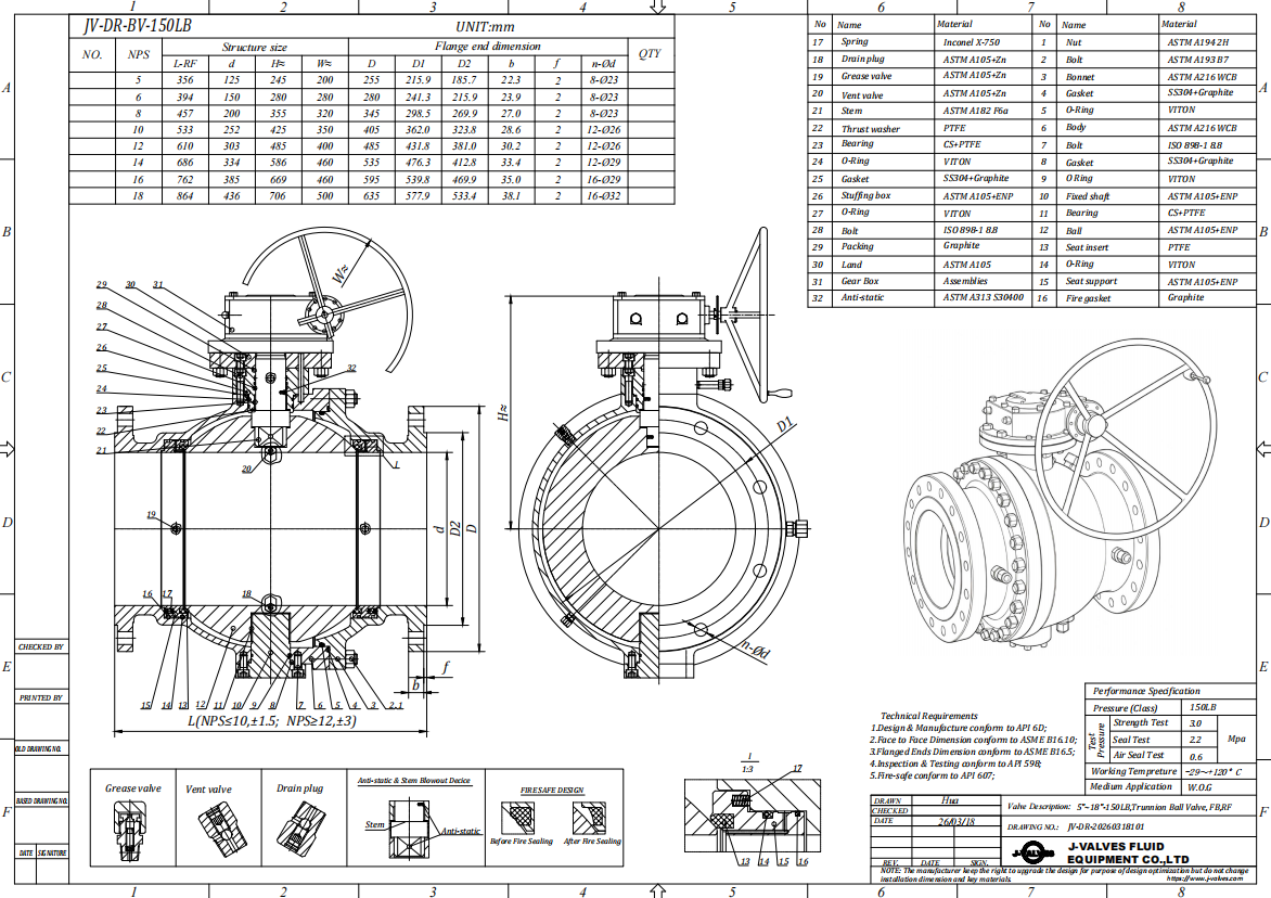
Bolt count on a trunnion mounted ball valve follows gasket seating load, not pressure end load, and climbs fast on a two piece body: DN50 8 × M16, DN100 12 × M20, DN150 16 × M24, DN200 20 × M24, DN300 24 × M30, DN400 28 × M33, DN600 32 × M36, DN900 36 × M42. Studs are A193 B7 with A194 2H nuts, B7M at 22 HRC for sour duty, A320 L7 below −29 °C.
Gaskets follow class. Spiral wound 316L with graphite filler and a carbon steel outer ring covers Class 150 to 600; from Class 900 the joint is a ring type joint in soft iron or 316L matched to groove hardness. Graphite sheet suits water below 200 °C and little else, because it has no recovery under thermal cycling.
Alignment decides whether the gasket lives. Two dowels locate the closure, and the joint gap is checked with a feeler at four points, 0.10 mm maximum, before any stud is tightened. Studs come up in three passes at 30, 60 and 100 percent in a star pattern, plus a second final pass, because each stud relaxes as its neighbours load. Dry threads scatter plus or minus 25 percent; with molybdenum disulphide at k = 0.16, M24 lands near 480 Nm, M30 near 950 Nm, M36 near 1650 Nm.
Three field errors recur. A compressed gasket is reused and loses 20 to 30 percent of its recovery. An RTJ groove is wire brushed, which rounds the crest that does the sealing. One side is preloaded before the other, so elastic interaction drops the first studs by 15 to 25 percent and the far side opens under pressure. None of the three shows up in an ambient hydrotest.
Stem, Bearings and the Materials Behind Them
Bearing choice is set by temperature and cycle count. A PTFE and glass liner in a stainless shell carries 25 MPa of projected pressure at 20 °C, 15 MPa at 150 °C and 8 MPa at 200 °C, at a friction coefficient near 0.05. PEEK carries 45 MPa to 200 °C, needs a 0.15 to 0.3 µm journal finish and costs three to four times as much. Bronze-backed PTFE takes the highest load and suits large slow-turn valves at 0.08 to 0.12 friction.
Journal diameter is not free. Torsional shear runs as 16T divided by πd³, so a 70 mm F316 stem at 2400 Nm sees 36 MPa, about half the allowable, and the same stem at 5000 Nm reaches 74 MPa and forces 80 mm or 17-4PH. The same arithmetic is why the bottom journal of a 36 inch valve is long rather than a short pin: projected area, not diameter, sets liner pressure.
Anti-blowout is a machined shoulder under the gland flange, proven by a pull test with the packing removed and the body pressurised. A replacement stem turned without that shoulder passes the same hydrotest and is still unsafe, so the feature belongs on the drawing and in the spare parts description.
Static discharge is a spring plunger bridging stem and body, held below 10 ohm and measured before and after the fire test. Graphite packing conducts by accident; replace it with PTFE and the path disappears.
Failure Modes Seen in the Field
These eight are the returns that arrive with a story attached, on a trunnion mounted ball valve that was usually specified correctly.
| Symptom | Mechanism | Field action | Prevention |
|---|---|---|---|
| Body joint weeps after a warm day | Cavity liquid expands 0.45 MPa per °C, lifts the closure and extrudes the gasket face | Bleed the cavity, re-torque to 100 percent in star pattern, change the gasket if the ring is crushed | Self-relieving seat, or a 25 bar body relief on every DIB-1 order |
| Seat leak that starts slowly | Particles rolled between insert and ball plough a groove along the sweep path | Cycle twice at low differential to flush, then re-test; a deep groove needs a seat kit | Upstream filtration, metal seat, or a scraper edge on the retainer |
| Torque doubles in a year | Sand reaches the bottom journal, mixes with grease and laps the liner | Purge and regrease the bottom cover, measure torque before and after | Sealed and greased cover, journal wiper, or a top entry body |
| Damp trace at the stem | Packing takes a set under cycling, the follower loses preload, a path opens at the stem wall | Re-tighten the gland in quarter turns at zero pressure; live-load washers if it returns | Graphite packing under Belleville load, ISO 15848-1 Class BH |
| Actuator strokes, valve still passes | Stop bolt set on actuator travel, not ball position: the ball sits 5 to 8 degrees off seat | Set the closed stop with the body drained and a leak test running, then lock and mark it | Commission against a measured leak, not the indicator plate |
| Paint blisters in patches | Weld spatter left under the primer; moisture enters the holiday and lifts the film | Strip, blast to Sa 2.5, re-prime and re-top inside the recoat window | Profile 50 to 75 µm, DFT 250 to 350 µm, 5 kV holiday test |
| Ball locked after a shutdown | Deposit cements ball to seat, or thermal contraction pinches the seat at low temperature | Warm within rating, torque the stem top only, never the gear housing | Seat clearance sized for the cold case, drain before long shutdowns, cycle quarterly |
| Seat O-ring nibbled | Elastomer extrudes into the carrier gap above roughly 60 percent of rating | Fit a seat kit, check the carrier for a burr before refitting | Back-up ring, or a PEEK insert where high differential is the design case |
Two are selection errors and six are commissioning errors, which is the proportion the return records show.
A Selection Decision Tree
Six judgements settle the configuration of a trunnion mounted ball valve, and the thresholds are the useful part.
Above DN200 or below? Below DN200 with a differential under 2.5 MPa, price a floating valve first. At DN200 and above, or above 2.5 MPa at any size, continue.
Differential above 60 percent of rating? Yes means near-full piston load: back-up ring, or PEEK above 100 °C. No means a standard RPTFE insert.
Solids above 500 mg/L, or particles harder than 3 Mohs? Yes goes to a metal seat with a scraper edge and a 68 to 72 HRC ball overlay, and the torque multiplier becomes 1.8 to 2.5.
More than one cycle a day? Yes means PEEK or bronze-backed bearings, a stem sized on fatigue, and a stated cycles-per-hour figure on the actuator datasheet. No allows a PTFE liner and a hand gear.
Buried or in a pit? Yes moves a trunnion ball valve to a fully welded body with an extended stem, because a bolted body underground has three joints nobody can reach.
DBB in the isolation philosophy? Yes requires double piston DIB-1 seats, a cavity bleed and an external relief, and the relief belongs in the valve budget, not the piping budget.
The order is by cost of being wrong, not frequency. Item 6 wrong adds hardware, item 5 wrong adds an excavation, item 3 wrong adds a seat kit every eight months for the life of the line.
Materials for Sour and Cold Service
Material on a trunnion mounted ball valve is usually decided by one of two clauses rather than by corrosion theory: a minimum design temperature below −29 °C, or an H2S partial pressure that puts the valve inside NACE MR0175.
| Grade | Standard | Range | Sour service | What decides it |
|---|---|---|---|---|
| WCB | ASTM A216 | −29 to 425 °C | Acceptable at 22 HRC, PWHT usually required | Cheapest body, no impact test unless asked |
| LCC | ASTM A352 | −46 to 345 °C | Acceptable at 22 HRC after PWHT | Charpy 27 J at −46 °C is why it exists |
| A350 LF2 | ASTM A350 | −46 to 343 °C | Acceptable at 22 HRC | Forged bodies, Class 900 and above |
| CF8M | ASTM A351 | −196 to 538 °C | Acceptable if solution annealed and verified | Cast austenitic, ferrite affects cracking |
| F316 | ASTM A182 | −196 to 538 °C | Acceptable, cold worked bar may exceed | Forged stems and small bodies |
| F51 duplex | ASTM A182 | −29 to 300 °C | Acceptable within its hardness limit | Chloride resistance, sigma above 300 °C |
The 22 HRC limit is the clause that changes drawings. It covers body, closure, ball and stem, and it is measured after welding and heat treatment rather than taken from the mill certificate, because hard facing and repair welds are where it goes wrong. B7M at 22 HRC max is a different purchase from B7 at 35 HRC; both fit the same nut and only one belongs on a sour line.
Cold service adds a constraint unrelated to toughness. From 20 °C to −46 °C, PTFE contracts about 0.6 percent linearly, so the insert shrinks off the ball and a valve that held 6 bar air in the shop can leak at 2 bar in the plant. The spring stack needs travel to follow that, and BS 6364 is where the requirement is written down.

Testing and the Inspection Test Plan
An ITP earns its keep when the witness points sit where a defect can still be fixed. On a trunnion mounted ball valve that means PMI before machining, hardness before assembly, and the seat test after the shell test, because body strain from the shell test can disturb a seat already accepted.
| Operation | Inspection or test | Reference | Level |
|---|---|---|---|
| Incoming material | PMI on body, closure, ball, stem, every heat | ASTM A751, EN 10204 3.1 | H |
| Casting or forging | Visual 100 percent, UT above 50 mm section, MT on repairs | MSS SP-55, ASME B16.34 | W |
| Overlay and hard facing | Bond, thickness, procedure qualification | ASME IX, ASME B16.34 | W |
| Heat treatment | Hardness survey after PWHT, 22 HRC max on sour orders | NACE MR0175, ISO 15156 | H |
| Machining | Bore, flange facing, RTJ groove, face to face, trunnion centres | ASME B16.10, B16.5, B16.47 | R |
| Assembly | Gasket lot, stud torque log by serial, stem alignment | Internal procedure, ISO 5211 | W |
| Shell test | 1.5 times the 38 °C rating, 10 minutes, no leak | API 6D, API 598 | H |
| Seat test, each seat | 1.1 times rating, cavity open and vented, both directions | API 6D | H |
| Low pressure seat | 5.5 to 6.9 bar air, bubble count over hold time | API 598 | W |
| Anti-static, blowout | Below 10 ohm, stem pull with packing removed under pressure | API 6D | W |
| Coating | Preparation, DFT 250 to 350 µm, 5 kV holiday test | ISO 12944, internal spec | R |
| Final and packing | Marking, tag plate, flange protection, document pack | API 6D, EN 10204 3.1 | R |
H is hold, W is witness, R is document review. Marking every line H buys a four-week delay and nothing else; the three worth holding are PMI, hardness after heat treatment, and the two pressure tests.
Site Installation: What Goes Wrong Before First Cycle
Most first-year failures are installation failures, and five cover the majority.
Misalignment. Flanges that are parallel but offset 3 mm put a bending moment into the body joint that no preload absorbs; the gasket unloads on one side and weeps at the first thermal cycle. Align pipe to 0.5 mm at the face and 0.3 mm per 100 mm of flange diameter for parallelism, and never pull a gap with studs.
Stud preload. A wrench set to the drawing value on dry threads delivers about 70 percent of the intended load, with plus or minus 25 percent scatter. Lubricate, torque in three passes, then repeat the final pass: on a DN600 joint it usually finds four or five studs low.
Support. Above DN400 a trunnion mounted ball valve is a structural element. A bare DN600 Class 300 body weighs 3.1 tonnes before the actuator; unsupported, that weight reaches the mating flanges as bending and opens the joint at the bottom. Support the valve on its own saddle, not on the pipe.
Hot re-tightening. A joint at 200 °C loses preload to differential expansion, since studs grow more than the flange pack. Re-torque at temperature after the first cycle and after the first cool-down, record both, and never tighten a live joint.
Water left after the hydrotest. Water expands about 9 percent on freezing and the pressure rise is not gradual; a closed cavity will split a body or lift a closure over one winter. Drain through the bleed, blow until no mist comes out, and leave the valve half open if the site is unheated.
Where the Cost Actually Sits
On a DN300 Class 300 valve, material is 32 to 38 percent of ex-works price, machining 18 to 22, assembly and testing 8 to 12, paint and documentation 5, actuator 15 to 25 when supplied. At DN600 material is nearer 45 percent; at DN150 it is under 30 and machining leads.
The size step is steep and predictable: price scales roughly with diameter to the power 2.4, so DN300 to DN400 adds about 70 percent and DN300 to DN600 about 4.5 times, the same exponent that governs weight.
Two non-standard items carry a fixed engineering charge. A non-standard face to face needs a new pattern or fixture and a first-article check: 8 to 15 percent at DN300, nearer 15 at DN750. An extended stem adds 6 to 12 percent at mid size and less when large, because it changes the bracket and actuator mount rather than the mass.
The actuator share moves most: 10 to 15 percent at DN150, 35 to 45 percent at DN600 with spring return, and a gas-over-oil system at DN900 can exceed the valve. Batch breaks are modest: 5 to 19 pieces about 6 percent against a single piece, 20 to 49 about 12, 50 and above about 18.

Against Gate, Globe, Butterfly and Plug
Each row closes with the case where another valve wins.
| Criterion | Trunnion ball | Gate | Globe | Butterfly | Plug |
|---|---|---|---|---|---|
| Pressure drop, open | Nil, highest Cv per bore | Low, above a ball | 3 to 5 times a ball | 0.3 to 0.6 of a ball | Low, near full port |
| Tight shut-off, both ways | Yes, both seats, rate A soft | No, direction dependent | No, one way | Moderate, elastomer dependent | Yes, with a sleeve |
| Solids | With metal seat and scraper | Solids jam the wedge pocket | Poor, seat in the flow | Poor at the disc edge | Fair, the sleeve wipes |
| Space | Shortest at the bore | Tall bonnet, long travel | Short face, tall bonnet | Shortest, wafer style | Short, tall actuator |
| Relative cost DN300-300 | 1.0 | 0.9 to 1.1 | 1.1 to 1.3 | 0.35 to 0.5 | 1.2 to 1.5 |
| Maintenance in line | Seat kit and packing, body stays | Repack only; a seat needs the line cut | Trim in line, bonnet off | Disc and liner in line | Sleeve in line |
| Where it wins | Isolation, pigging, high differential | Cheap clean water and steam isolation | Throttling, never isolation | Large low pressure, tight space | Abrasive slurry with a changeable sleeve |
The conclusion is narrow. For isolation at Class 300 and above, on gas or a pigged line, this is the default, and the alternatives cost more over ten years even when they cost less at the order. For throttling it is the wrong valve: a ball half open puts the whole differential across an unsupported seat edge and erodes it in weeks.

What to Send with an Enquiry
Ten items turn an enquiry into a quotation without a round of questions. Each changes the drawing.
Line class sheet, tag number and piping material class.
Shut-off differential, and whether the valve closes against flow.
Solids: mg/L, particle size, hardness, and whether the line is pigged.
H2S and CO2 partial pressure, chloride in ppm, if any is present.
Design temperature at both ends, plus ambient at the actuator including solar gain.
Cavity relief philosophy: self-relieving seats or a body relief valve with a set pressure.
Stroke time and cycles per day, since both decide actuator and bearing liner.
Piping loads at the flanges, or a statement that the valve is independently supported.
Paint system and DFT, insulation, fire-safe and fugitive-emission certificates.
Documentation: EN 10204 3.1, ITP level, third-party inspector, spare seat kits.
Delivery is 4 to 8 weeks depending on configuration and material availability, and any non-standard dimension is drawn and approved before machining. An enquiry for a trunnion mounted ball valve that answers items 1, 2 and 5 gets a firm price; a size and a class alone gets a range and a question.
Hot Products


News
Ball Valves in Geothermal Brine: Silica Scale, Chloride Cracking And The Cooling Trap
Why geothermal brine destroys ball valves: retrograde silica scale, calcite at the flash point, chloride cracking above 60 C and the 250 C seat limit.
Read More
Ball Valve Face To Face Dimensions: Why A Correctly Ordered Replacement Still Does Not Fit
A 6 inch Class 150 ball valve can be 267 or 305 mm face to face and both are compliant. How B16.10, EN 558 and flange drilling decide whether it fits.
Read More
Ball Valve Stem Key And Keyway: What Gives Way First, And What The Handle Cannot Tell You
Between the handle and the ball there are four fits. Which one shears, which one cracks, and how a few degrees of lost motion hides a valve that never seated.
Read More
Ball Valve Datasheet: Six Blocks That Decide Whether Two Quotes Are Comparable
A ball valve datasheet only works when six blocks are fixed: pressure basis, bore, temperature ceiling, test, end connection, operator. How each is written.
Read More