


CHINA J-VALVES Offers Various High-quality I ndustrial Ball Valves
J-VALVES, a distinguished professional ball valve manufacturer rooted in China, takes pride in its extensive product portfolio. Our offerings span a wide range, including trunnion-mounted ball valves, floating ball valves, high-temperature ball valves, high-pressure ball valves, metal-sealed ball valves, ultra-low temperature ball valves, DBB ball valves, Three-way And Four-way Ball Valve, and fully welded ball valves. Each product is a testament to our commitment to precision engineering and reliable performance. Meticulously crafted, they are designed to not only meet but exceed the most stringent industrial demands, ensuring stable operation even under extreme conditions. This enables us to provide our clients with high-value services and makes our valves widely sought-after in industries.
Product Category
Contact Us


-
J-VALVES-Q47F
-
J-VALVES
Overview of the J-VALVES 30 Inch 900LB A105 Trunnion Ball Valve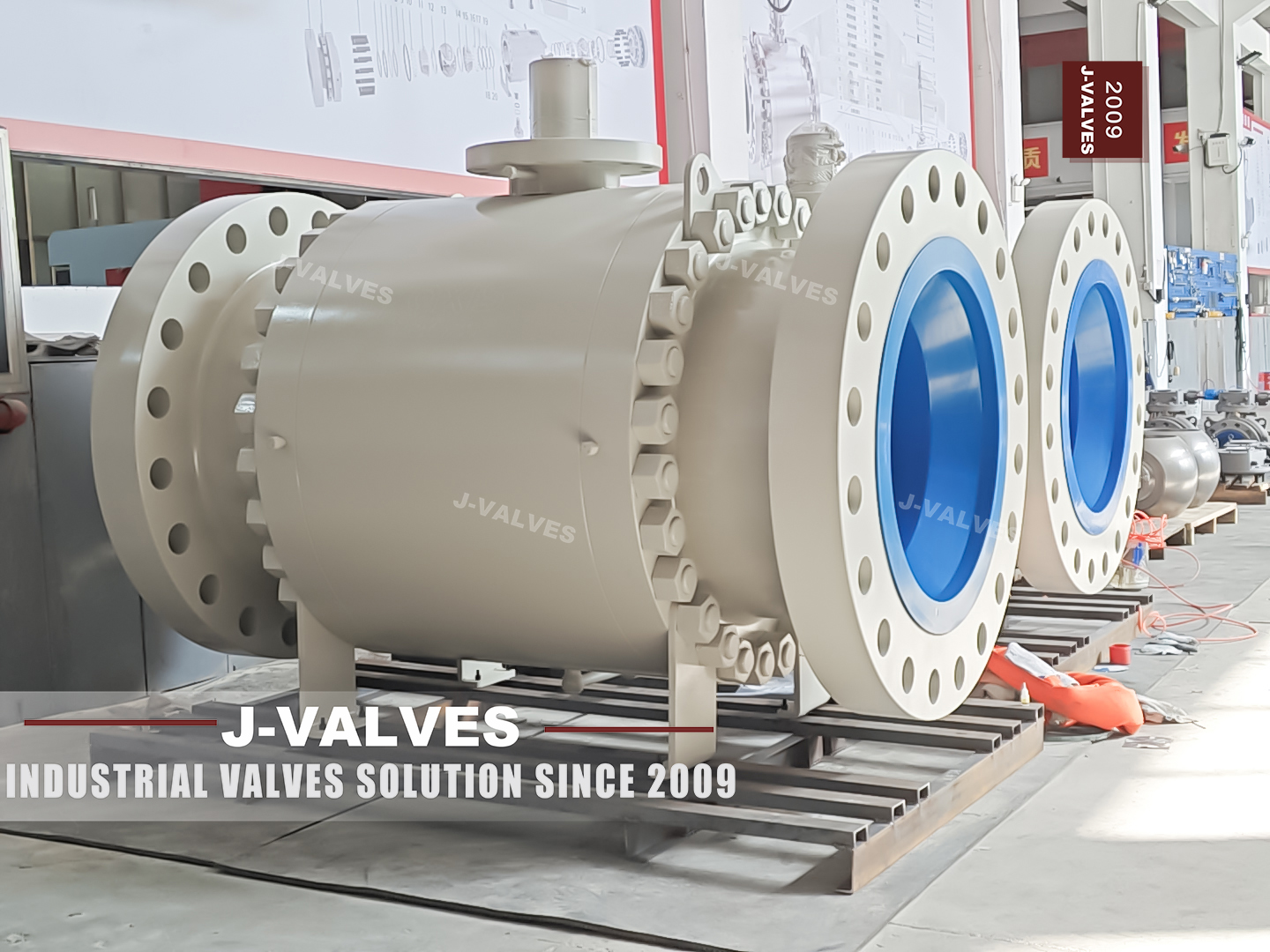
This is a thirty inch full bore valve: DN750, Class 900, which API 6D writes as PN150. The body is ASTM A105 forged carbon steel in three bolted pieces, the ends are ring type joint flanges to ASME B16.5, and the ball is carried on upper and lower trunnions so that it turns in place instead of being pushed downstream by the pressure. A worm gear with a handwheel is the standard operator, and the whole assembly is built to be lifted by crane.
At this size the valve stops being a component and becomes a piece of plant. A thirty inch Class 900 body is heavy enough that it is lifted with a crane rather than by two fitters, the operator is a gearbox with a handwheel because no lever can produce the torque, and the flange joint is a ring type joint because a raised face gasket is not reliable at this pressure and this diameter.
Those four facts decide how the valve is bought, shipped and installed, and they are what this page is about. The sealing principle is the same as on a six inch valve; what changes is that every load is multiplied by the bore and every tolerance is multiplied by the diameter, so the parts that were secondary at DN150 become the design drivers at DN750.
Design and Construction
In a trunnion mounted valve the ball does not float. It is held between two trunnions, one above and one below, running in bearings that take the load the pressure puts on the ball. Because the ball cannot move, the seats have to move instead: each seat is a piston that the line pressure pushes against the ball, and the seal is made at the seat face rather than by the ball being driven into it.
That is what makes a large valve operable. On a floating valve the whole pressure load becomes friction on the seat and the torque climbs with the cube of the bore; on a trunnion valve the load goes into the bearings and the torque stays within what a gearbox can deliver. At DN750 this is not a refinement, it is the only way the valve can be turned by one person on a handwheel.
Each seat can be single piston effect or double piston effect, and the difference shows up during maintenance and during cavity relief. With double piston effect both seats seal against pressure from either side, which is what a double block and bleed duty needs; with single piston effect the upstream seat is pushed clear and the cavity vents to the upstream side. The choice belongs in the order, because it changes the seat parts.
The body is three pieces with two bolted joints, one each side of the centre section. At this diameter each joint is a ring of large studs closing a gasketed face, and it is the part of the valve most likely to leak if it is assembled carelessly. The reward is that the ball, seats and trunnion bearings can be reached without cutting a thirty inch pipeline, which on a transmission line is the difference between a shutdown and a repair.

Material Options
A105 is the specified body grade: forged carbon steel, normalised, with good toughness and a rating band that runs from minus 29 to plus 425 degrees Celsius. A350 LF2 is the low temperature alternative for service down to minus 46 degrees, and A182 F316 or F316L is the stainless upgrade where the medium is corrosive. At DN750 the body parts are large, so the form each part takes is fixed on the drawing before the order is released, not chosen at the machine.
The trim is where the wear sits. Ball in A105 with electroless nickel plating as standard, hard chrome where the medium is mildly abrasive, and tungsten carbide or cobalt alloy hardfacing where sand or catalyst fines are present. Stem in 17-4PH precipitation hardening stainless, with a nickel alloy 718 stem for the highest torque duties. Seat in PEEK, in metal with a flexible graphite seal, or in nickel alloy 718 with tungsten carbide for abrasive service.
| Component | Standard Material | Optional Upgrade | Service Notes |
|---|---|---|---|
| Body and end caps | ASTM A105 forged carbon steel | A350 LF2, A182 F316 or F316L | three pieces, two bolted joints |
| Ball | A105 with electroless nickel plating | hard chrome, tungsten carbide, cobalt alloy hardfacing | carried on trunnions, ground and lapped |
| Trunnion and bearings | Surface hardened A105 | 17-4PH | takes the pressure load off the seats |
| Stem | 17-4PH precipitation hardening stainless | nickel alloy 718 | blowout proof, keyed to the ball |
| Seat ring | PEEK | metal with flexible graphite, nickel alloy 718 with tungsten carbide | single or double piston effect |
| Body gasket | Ring type joint metal ring | soft iron, low carbon steel, F316 plated | new ring at every joint opening |
| Packing | Flexible graphite with wire reinforcement | Not applicable | fire safe configuration |
| Body studs | ASTM A193 B7 with A194 2H nuts | B7M with 2HM, B8M with 8M | taken up in stages to the specified load |
| Operator | Worm gear with handwheel | pneumatic-hydraulic, electric, hydraulic | pad and stem top machined for actuation |
Technical Specifications
Everything on this page is sized from the flange. DN750 full bore, ring type joint flanges to ASME B16.5, Class 900 rating, and a face to face length from ASME B16.10 that decides whether the valve drops between the two spools already welded on site. Three forged A105 sections carry the bore; a gearbox with a handwheel turns it, because no lever of usable length will break a trunnion ball out at this diameter. Butt weld ends to ASME B16.25 can replace the flanges, and the length then comes off the drawing. Testing is to API 598 and API 6D.
Three choices have to be settled before a price means anything. Full bore or reduced bore, because it changes the ball, the body and the weight; ring type joint or raised face, because it changes the flange machining and the gasket; and gear only or geared with an actuator mounting flange, because a valve that will later be automated has to be built with the pad and the stem top for it.
| Item | Value |
|---|---|
| Nominal size | 30 x 30 inch full bore (DN750) |
| Pressure class | Class 900 (PN150) |
| Body construction | three piece, two bolted joints |
| Ball support | trunnion mounted, upper and lower bearings |
| Body material | ASTM A105 forged carbon steel |
| Body options | A350 LF2, A182 F316, A182 F316L |
| Material group | ASME B16.34 group 1.1 carbon steel |
| Rating at 38 C | Class 900 = 153 bar |
| Temperature range | minus 29 to plus 425 C for A105 |
| Ball | A105 with electroless nickel plating |
| Ball options | hard chrome, tungsten carbide, cobalt alloy hardfacing |
| Trunnion | surface hardened A105 |
| Trunnion option | 17-4PH |
| Stem | 17-4PH precipitation hardening stainless |
| Stem option | nickel alloy 718 |
| Seat | PEEK |
| Seat options | metal with flexible graphite, nickel alloy 718 with tungsten carbide |
| Seat effect | single or double piston effect, stated on the order |
| Body gasket | ring type joint metal ring |
| Body studs | ASTM A193 B7 with A194 2H nuts |
| Stud options | B7M with 2HM, B8M with 8M |
| End connection | ring type joint flange to ASME B16.5 Class 900 |
| End option | butt weld to ASME B16.25 |
| Face to face | ASME B16.10 |
| Wall thickness | ASME B16.34 |
| Design standards | ASME B16.34, API 6D and API 608 |
| Fire safety | API 607 where ordered |
| Pressure testing | API 598 and API 6D, shell and seat |
| Operator | worm gear with handwheel |
| Actuation options | pneumatic-hydraulic, electric, hydraulic |
| Cavity relief | per API 6D, seat effect stated on the order |
| Marking | size, class, A105 and heat number on the body and nameplate |
| Documentation | EN 10204 3.1, test record, general arrangement drawing |
Standards and Compliance
ASME B16.34 sets the wall thickness and the pressure temperature rating. A105 is a carbon steel in material group 1.1: Class 900 corresponds to 153 bar at 38 degrees, and the group is rated up to 425 degrees, above which the material is not to be used because of graphitisation rather than because the wall would fail. API 6D adds the pipeline valve requirements, including the cavity relief and the anti static provisions.
The ring type joint is not a preference at this size, it is what the flange standard provides for. ASME B16.5 gives the groove dimensions and the ring gasket sits in a confined groove, so the seal is made by metal to metal contact and the bolt load compresses the ring rather than a soft gasket. API 598 and API 6D between them set the shell and seat tests, and the fire test to API 607 is added where the project asks for it.
| Requirement | Standard | What J-VALVES Supplies |
|---|---|---|
| Wall thickness and rating | ASME B16.34 | group 1.1 carbon steel, Class 900 = 153 bar at 38 C |
| Pipeline valve requirements | API 6D | cavity relief, anti static, marking |
| Ball valve specifics | API 608 | blowout proof stem, nameplate content |
| Flanges and ring grooves | ASME B16.5 | Class 900 ring type joint dimensions |
| Face to face | ASME B16.10 | long pattern for the class and size |
| Butt weld ends where ordered | ASME B16.25 | end preparation drawing |
| Pressure testing | API 598 and API 6D | shell at 1.5 times, seat at 1.1 times |
| Material certificate | EN 10204 3.1 | certificate per heat, with impact test where ordered |
Manufacturing Process
The body parts are machined on a boring mill large enough to cut the bore, the seat pockets and the joint faces in one setting. That matters more at this size than at any other: a joint face that is not flat and parallel over a thirty inch diameter will leak no matter how much torque is put on the studs, and the error cannot be corrected by tightening. Flatness is measured on the face, not inferred from the finished valve.
The ball is machined, ground and lapped, then plated or hardfaced, and checked for roundness against the seat rings it will run against. Assembly is the centre section on stands, seats and trunnions in, ball lowered in with the crane, end caps on, studs taken up in a cross pattern in stages to the specified load, then the gearbox fitted and the travel stops set so the ball seats exactly at open and closed.

Quality Control and Testing
Every valve is shell tested at one and a half times the rating and seat tested at one point one times, to API 598 and API 6D. On a thirty inch valve the shell test is a slow business: the body has to be filled, vented, brought up in steps and held long enough for the water to stop moving, and the two bolted joints are watched separately because a weep there is a body leak, not a seat leak.
The material and dimensional record is issued with the valve. Ultrasonic testing of the forgings, chemical composition and mechanical properties per heat, hardness of the ball and the seat facing, flange groove dimensions to ASME B16.5, face to face to ASME B16.10, and the operating torque measured with the gearbox fitted. That torque figure is what an actuator has to be sized on, and it cannot be estimated from the bore.
| Step | What Is Checked | Standard or Acceptance |
|---|---|---|
| Incoming forging | chemical composition, mechanical properties, ultrasonic testing | EN 10204 3.1 against A105 |
| Machining | bore, seat pocket, joint face flatness and parallelism | drawing tolerance, measured on the face |
| Ball | roundness, surface finish, plating or hardfacing thickness | drawing range, checked against the seat ring |
| Flange | ring groove dimensions, bolt circle, facing finish | ASME B16.5 Class 900 |
| Body joints | stud grade, gasket, tightening sequence and final load | specified torque in three passes |
| Shell test | body and both bolted joints at 1.5 times | API 598, no leak, held for the specified time |
| Seat test | each seat in both directions at 1.1 times | API 598 and API 6D, no visible leak |
| Torque | breakaway and running torque with the gearbox fitted | recorded and issued for actuator sizing |
| Gearbox | travel stops at open and closed, indicator setting | ball seats exactly at both ends of travel |

Applications and Industry Service
The duty is main line isolation on transmission pipelines, compressor station suction and discharge, meter runs, storage terminal headers and large seawater or cooling water lines where the pressure is high and the volume flow is large. In those places the valve is normally fully open or fully closed for years at a time, and the reason to buy a good one is that the day it has to close, it has to close completely. A pigging run has to pass through the bore without meeting a seat edge, which is the other reason the port is full and the cavity is kept out of the flow path.
It is the wrong valve for throttling or for modulating control. At thirty inch the flow energy is high enough to damage a seat that is held part open, and a ball valve used that way will lose its seal long before its design life. Where control is needed, the ball valve isolates and a separate control valve does the regulating, which is how these stations are actually built.

Installation, Operation and Maintenance
Lift the valve on the body lugs with a spreader, never on the gearbox or the stem, and never on the flange bolt holes. Support the pipe on both sides so that the valve body does not become the pipe support, and check that the flanges are parallel before the studs are drawn up: pulling a thirty inch joint closed with the bolts puts a bending load into the body that no pressure test will reveal.
A ring type joint uses a new ring every time the joint is opened, and the groove is inspected for damage before the new ring goes in. Studs are lubricated and taken up in a cross pattern in at least three passes to the specified torque. After the first thermal cycle the joint is checked again, because relaxation on a joint this size is normal and re torquing once is part of commissioning, not a sign of a fault.
How to Specify and Order
Write the size, the class, the body grade, the bore, the facing, the seat effect, the operator and the test. A typical line reads: 30 inch, Class 900, body A105, full bore, ring type joint flanges to ASME B16.5, double piston effect seats, worm gear with handwheel, tested to API 598 and API 6D. If the line will be pigged, say so, because full bore is the requirement and reduced bore will not pass a pig.
Also state the medium, the design temperature, whether an actuator will be fitted now or later, and the transport limits at site. A thirty inch valve may have to be shipped in one piece, and the lifting points and the sea fastening are part of the delivery. Sending those details with the enquiry avoids a valve that arrives sound and cannot be lifted into position.
FAQ
Q: What does 30x30 mean in the product name?
A: It means full bore at both ends: a thirty inch bore through a thirty inch valve, with thirty inch flanges on both sides. A reduced bore valve would be written 30x24 or similar, with a thirty inch flange and a smaller bore through the ball. The distinction matters because only a full bore valve passes a pig, and a reduced bore valve cannot be converted into one later.
Q: Why ring type joint flanges instead of raised face?
A: Because at Class 900 and thirty inch a soft gasket is not a reliable seal. A ring type joint uses a metal ring confined in a groove, so the seal is metal to metal and the bolt load compresses the ring rather than squeezing a sheet. The cost is that the groove has to be undamaged and a new ring goes in every time the joint is opened.
Q: Is A105 the right body material at this size?
A: A105 is the grade specified on this valve and it is a forging grade with a rating band from minus 29 to plus 425 degrees. At DN750 the body parts are large, so the form each part takes is fixed on the drawing before release. If a foundry route such as A216 WCB is proposed as an alternative, it has to be agreed in writing as a material substitution, not assumed.
Q: Can the valve be actuated instead of geared?
A: Yes, and it should be decided at the order stage. The gearbox is replaced by a mounting interface for a pneumatic-hydraulic, electric or hydraulic actuator, and the stem top is machined for the drive. Retrofitting on site means changing the gearbox adaptor and often the stem, on a valve that weighs several tonnes and is already in the line.
Q: What is the temperature limit?
A: Minus 29 to plus 425 degrees Celsius for an A105 body. The upper limit is a material limit rather than a wall thickness limit: above 425 degrees carbon steel is subject to graphitisation, so the answer is not a thicker body but a different grade, such as F11 or F22 low alloy, or an austenitic stainless.
Q: How is a valve this size tested?
A: Shell test at one and a half times the rating and seat test at one point one times, to API 598 and API 6D. The body is filled and vented, brought up in steps and held long enough for the water to settle, and the two bolted joints are watched separately from the seats. Torque is measured with the gearbox fitted and issued for actuator sizing.


Hot Products


News
Ball Valves in Geothermal Brine: Silica Scale, Chloride Cracking And The Cooling Trap
Why geothermal brine destroys ball valves: retrograde silica scale, calcite at the flash point, chloride cracking above 60 C and the 250 C seat limit.
Read More
Ball Valve Face To Face Dimensions: Why A Correctly Ordered Replacement Still Does Not Fit
A 6 inch Class 150 ball valve can be 267 or 305 mm face to face and both are compliant. How B16.10, EN 558 and flange drilling decide whether it fits.
Read More
Ball Valve Stem Key And Keyway: What Gives Way First, And What The Handle Cannot Tell You
Between the handle and the ball there are four fits. Which one shears, which one cracks, and how a few degrees of lost motion hides a valve that never seated.
Read More
Ball Valve Datasheet: Six Blocks That Decide Whether Two Quotes Are Comparable
A ball valve datasheet only works when six blocks are fixed: pressure basis, bore, temperature ceiling, test, end connection, operator. How each is written.
Read More