


CHINA J-VALVES Offers Various High-quality I ndustrial Ball Valves
J-VALVES, a distinguished professional ball valve manufacturer rooted in China, takes pride in its extensive product portfolio. Our offerings span a wide range, including trunnion-mounted ball valves, floating ball valves, high-temperature ball valves, high-pressure ball valves, metal-sealed ball valves, ultra-low temperature ball valves, DBB ball valves, Three-way And Four-way Ball Valve, and fully welded ball valves. Each product is a testament to our commitment to precision engineering and reliable performance. Meticulously crafted, they are designed to not only meet but exceed the most stringent industrial demands, ensuring stable operation even under extreme conditions. This enables us to provide our clients with high-value services and makes our valves widely sought-after in industries.
Product Category
Contact Us


-
J-VALVES-Q347F
-
J-VALVES
Overview of the J-VALVES 14 Inch Gear Operated Trunnion Ball Valve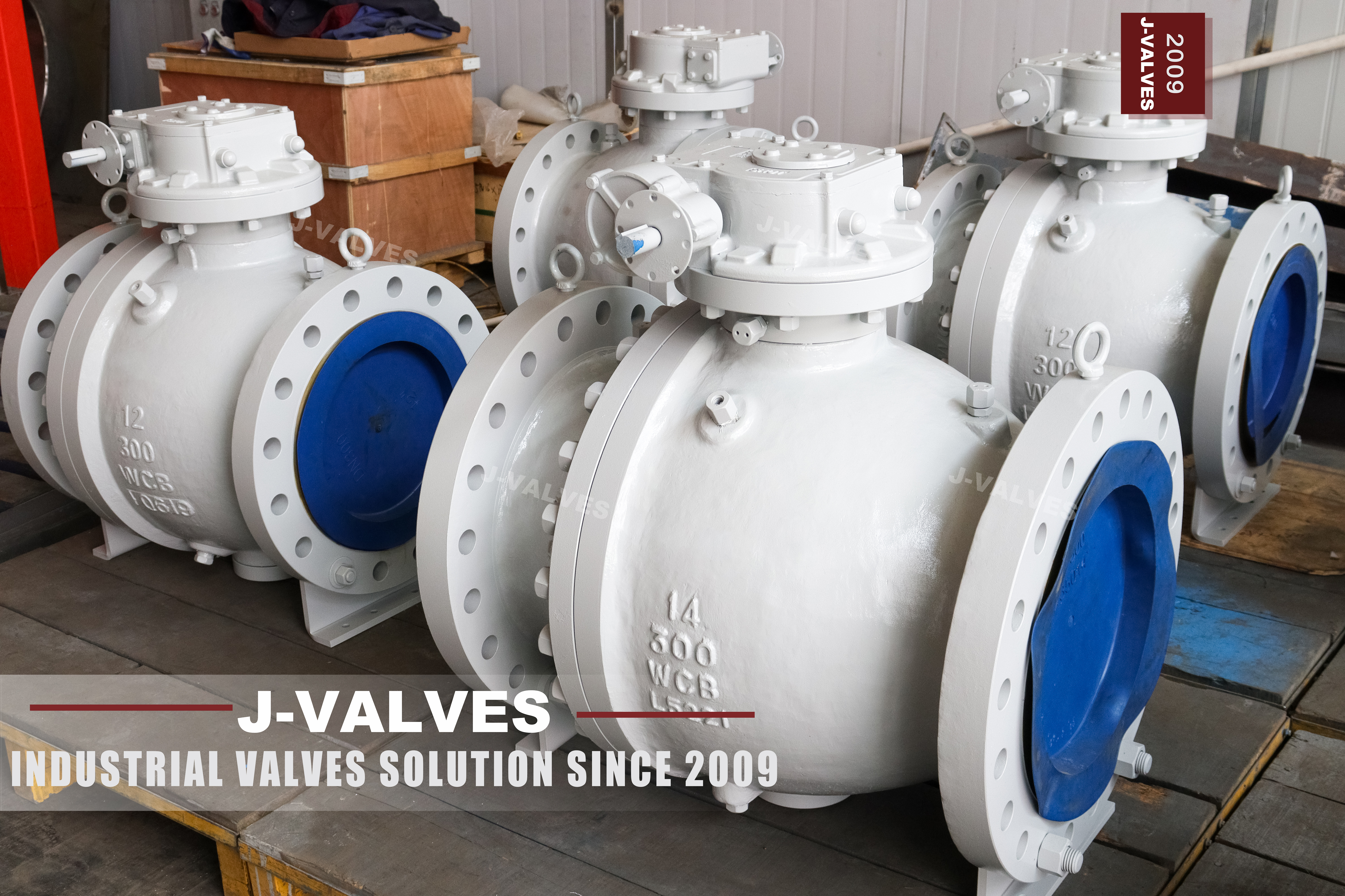
This is a fourteen inch Class 300 two piece trunnion mounted ball valve with a worm gear operator and a handwheel. The body is cast A216 WCB, the ball runs on a trunnion at the bottom and the stem at the top, and the seats are spring loaded and self relieving. The gear is not an accessory bolted on at the end: it is a build item, and the ratio is chosen against the measured torque of the assembled valve.
The original page did not mention the gear at all, although the product photograph is named for a gear operated valve. That is a search problem before it is a description problem: buyers looking for a large bore valve specify the operator, because at fourteen inch a bare stem is not a product anyone can use. The operator is now in the product name, the title and the attributes.
Design and Construction
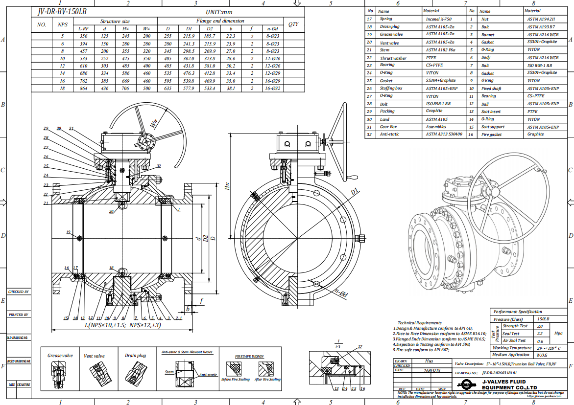
The body splits at one joint with the end cap downstream, and the joint sits on the low pressure side while the valve is closed. The ball is located by a trunnion at the bottom of the body and by the stem at the top, so it rotates in place rather than being pushed along the axis by line pressure. That is what keeps the operating torque inside a range a gearbox can handle at this bore size.
Each seat is pushed onto the ball by springs and relieves if cavity pressure rises above line pressure, so the valve seals in both directions and does not need an external cavity vent. The gearbox sits on an ISO 5211 pad on the neck, drives the stem through a keyed coupling, and carries a position indicator on top so that a partly open valve is visible from the walkway rather than being inferred from the handwheel.
Material Options
WCB is the right body for water, oil and gas at Class 300, and at DN350 the casting has to be sound at the joint face because that is the largest machined area on the valve. Radiography is available on request and is worth asking for on a valve this size, since a shrinkage cavity at the joint face is a leak that appears under test rather than in service.
The ball and trunnion take the wear, and at fourteen inch the ball is heavy enough that its own weight matters. The trunnion bearing carries that weight plus the seat load, which is why the bearing is a PTFE and graphite composite rather than a plain bush: it keeps the torque low enough that the gear ratio stays sensible. A hard chrome or ENP ball is standard; a stainless overlay is specified for abrasive service.
| Component | Standard Material | Optional Upgrade | Service Notes |
|---|---|---|---|
| Main body | ASTM A216 WCB | Impact tested WCB for low temperature | Carries the trunnion bearing at the bottom |
| End cap | ASTM A216 WCB | Same heat where required | Carries the downstream seat |
| Ball | WCB with ENP or hard chrome | Stainless overlay for abrasive service | Held on the trunnion, does not travel |
| Trunnion | A105 surface hardened | 17-4PH | Takes the seat load on a bearing |
| Bearing | PTFE and graphite composite | Stainless backed bush | Keeps the torque inside the gear rating |
| Stem | 17-4PH | A105 with ENP | Blowout proof, keyed to the ball |
| Seat | PTFE or RPTFE | PPL, PEEK, metal with graphite | Spring loaded and self relieving |
| Packing | PTFE V rings | Flexible graphite | Adjustable at the gland |
| Joint gasket | Spiral wound, graphite filler | PTFE envelope for clean service | Single use item |
| Operator | Worm gear with handwheel | Bevel gear or actuator | Ratio sized against the measured torque |
Technical Specifications
Three numbers on the drawing matter more than the rest. DN350 is the bore and the flange size, both full port. Class 300 sets the wall, the flange drilling and the test pressures. The face to face length to ASME B16.10 is long at this size, and it is the dimension that decides whether the valve fits into an existing pipe run, so it is measured rather than assumed.
The gear ratio is the fourth number and it is derived rather than chosen. It comes from the measured breakaway torque at the rated pressure divided by the input torque a person can apply comfortably, and it changes if the seat compound changes. A gear selected from a table before the seat is decided is a gear that may have to be changed after the first test, which is a schedule problem on a valve this size.
| Item | Value |
|---|---|
| Product type | Two piece flanged trunnion mounted ball valve |
| Nominal size | 14 inch, DN350 |
| Pressure class | Class 300 (marked 300LB), PN50 in the API 6D designation |
| Body material | ASTM A216 WCB cast carbon steel |
| Body construction | Two piece, one bolted joint, end cap downstream |
| Ball support | Trunnion mounted, upper and lower bearing |
| Ball | WCB or A105 with ENP, hard chrome, or a stainless overlay |
| Stem | 17-4PH, or A105 with ENP |
| Trunnion | A105 surface hardened, or 17-4PH |
| Seat | PTFE or RPTFE, -29 to 180 C |
| Seat option | PPL to 280 C, PEEK to 260 C, metal with graphite to 425 C |
| Seat design | Spring loaded, both seats independently energised |
| Cavity relief | Self relieving through the seat |
| Packing | PTFE V rings, flexible graphite option |
| Body joint gasket | Spiral wound with graphite filler |
| End connection | Flanged raised face, ASME B16.5 Class 300 |
| End option | Butt weld ends to ASME B16.25 |
| Face to face | ASME B16.10, held on the drawing |
| Bore | Full port, DN350 through the ball |
| Operator | Worm gear, handwheel, with a position indicator |
| Operator note | The gear is a build item, not an accessory added later |
| Design standard | ASME B16.34, API 6D, API 608 |
| Test standard | API 598, API 6D |
| Fire safe | API 607 with the seat compound supplied |
| Anti static | Ball to body continuity, measured per valve |
| Temperature range | -29 to 425 C body, ceiling set by the seat |
| Media | Water, oil, gas, process lines up to DN350 |
| Installation note | Pipe support on both sides, the valve is not a support |
| Marking | Size, class, material and heat number on the body |
| Traceability | EN 10204 3.1 certificate with the heat number |
Standards and Compliance
At fourteen inch the standards that carry weight are the ones about load rather than about geometry. ASME B16.34 sets the wall that has to hold Class 300 pressure across a large diameter, API 6D sets the cavity relief rule that keeps the body from being split by trapped pressure, and ISO 5211 sets the pad the gearbox bolts onto. API 608 then supplies the ball valve details and API 598 the test.
The operator adds one interface that has to be documented: the ISO 5211 pad size and the drive. On a valve supplied with a gear, the pad is still there underneath, and recording its size at the time of order is what makes a later conversion to a pneumatic or electric actuator possible without replacing the valve or machining a new bracket.
| Requirement | Standard | What J-VALVES Supplies |
|---|---|---|
| Wall and rating | ASME B16.34 | Cast wall tabulated for Class 300 at DN350 |
| Valve design | API 6D and API 608 | Pipeline design plus the ball valve specifics |
| Flange drilling | ASME B16.5 Class 300 | Raised face, twelve bolt pattern at DN350 |
| Face to face | ASME B16.10 | Length on the signed drawing |
| Pressure test | API 598 | Shell 1.5 times and seat 1.1 times the rating |
| Fire test | API 607 | Certificate against the seat compound |
| Cavity relief | API 6D requirement | Self relieving seat, direction marked |
| Gear operator | ISO 5211 interface | Pad and drive size stated on the drawing |
| Material certificate | EN 10204 3.1 | Heat number traced from the casting |
Manufacturing Process
The castings are normalised, then machined as a pair so the bore and the seat pockets line up across the joint. At DN350 the machining is done on a horizontal borer rather than a lathe, and the trunnion bore at the bottom of the body is cut in the same setting as the seat pockets, because a trunnion a few hundredths off centre loads the bearing on one side and shows up as a heavy handwheel.
The flange is drilled last from the ASME B16.5 table for Class 300 at DN350, and the twelve bolt pattern is indexed off the bore centre line. The valve is then assembled, torqued, tested and only afterwards fitted with the gearbox, so that the torque measurement is taken on the valve itself rather than through the gear.

Quality Control and Testing
Testing is the standard set for a trunnion valve plus two size specific checks. The shell test is run with the joint assembled and torqued, and at this diameter the joint has a long gasket path, so the test is held for the full time rather than shortened. The seat test runs in both directions and the cavity relief is checked before painting.
The size specific checks are the face to face length, measured against the drawing rather than a catalogue, and the gear torque, measured at the handwheel input and converted back to the stem to confirm the ratio. A gear that is correct on paper and heavy in the hand is a gear that was sized from a table figure, and the measured torque is what catches it before the valve ships.
| Step | What Is Checked | Standard or Acceptance |
|---|---|---|
| Chemistry | WCB range, carbon and manganese | Spectrographic analysis per heat |
| Casting | Porosity at the joint face and seat pockets | Visual and penetrant, radiography on request |
| Flange drilling | Twelve bolt pattern against ASME B16.5 | Gauged, recorded per valve |
| Face to face | Length against the drawing at DN350 | Measured, recorded with the gauge used |
| Shell test | Body and joint under pressure | 1.5 times the rating, held to API 598 |
| Seat test | Both directions | 1.1 times the rating, no visible leakage |
| Gear torque | Breakaway torque through the gear | Measured, gear ratio confirmed against it |
| Cavity relief | Seat lift at the designed differential | Checked on assembly, recorded |
| Anti static | Ball to body continuity | Measured in ohms per valve |

Applications and Industry Service
The valve is used on water transmission, oil and gas gathering, plant cooling water headers and process isolation where the line is fourteen inch and the valve is operated occasionally. At this size the operator is almost always a gear or an actuator, because a lever long enough to break the seat load would be a hazard on a walkway.
It is the wrong valve where the line will be pigged and the seat pockets present a ledge, where the medium carries chlorides, or where the valve has to modulate. It is also a poor choice where the pipe run cannot take the face to face length of a trunnion valve, since at DN350 that length is substantial and a shorter pattern valve may be the only thing that fits the space.

Installation, Operation and Maintenance
At fourteen inch the valve is a heavy item and the installation is a lifting job, not a two person job. Pipe supports go on both sides and the valve is not used to pull the flanges together; a WCB flange at this size is stiff enough to distort a gasket under an uneven pull, and the leak appears at the first thermal cycle rather than at commissioning.
The gearbox needs its own attention: the input shaft is greased at the intervals in the manual, and the position indicator is set with the valve as the reference rather than with the gear end stops. A seat change is a joint job and at this size the ball is lifted out with a sling, which means the space in front of the valve has to be planned for at the design stage rather than discovered at the shutdown.
How to Specify and Order
Replacing a valve at this size is a project rather than a purchase, so the order starts with a site measurement instead of a specification sheet. The gap between the existing flanges, the bolt circle on them, and the space available for lifting the ball out all constrain what can be supplied, and only after those are known do size, class, trim and operator come into it. A valve built to the class but not to the gap sits on a pallet while the line waits.
Ask for the material certificate to EN 10204 3.1, the pressure test record, the cavity relief check and the measured torque through the gear. Where a later actuator conversion is possible, record the ISO 5211 pad size and the drive now. Spares worth holding are a joint gasket, a seat and O ring kit, and a gearbox input seal, which is the part that fails first on a valve that is operated rarely.
FAQ
Q: Why does a 14 inch ball valve need a gear operator?
A: Because the breakaway torque at this bore size is beyond what a hand lever can apply comfortably, and a lever long enough to do it would be a hazard on a walkway. The worm gear multiplies the input torque, and its ratio is chosen against the measured torque of the assembled valve rather than against a catalogue figure.
Q: Is Class 300 the same as PN50?
A: Yes. API 6D clause 7.2 lists PN50 against Class 300. The valve is marked with the class and flanged to ASME B16.5 Class 300, which at DN350 is a twelve bolt pattern and is not the same as a PN50 flange to EN 1092-1.
Q: Can the gear be replaced with an actuator later?
A: Yes, if the ISO 5211 pad size and the drive are recorded at the time of order. The pad is under the gear on every valve of this design, so a pneumatic or electric actuator can be fitted later without machining a new bracket, provided the torque is known.
Q: Does this valve need a cavity relief vent?
A: No. The seats are self relieving, so pressure trapped in the body cavity lifts a seat and escapes to the low pressure side. That is an API 6D requirement for this design and the relief direction is marked on the body.
Q: How much space is needed in front of the valve for a seat change?
A: Enough to lift the ball out of the body with a sling, which at fourteen inch means planning the access at the design stage rather than at the shutdown. The end cap comes off the downstream side, so the space is needed on that side and not above the valve.
Q: Is a two piece body suitable at this size?
A: Yes. A two piece body has one joint and one gasket to manage, and at Class 300 the joint is well within what a bolted flange can hold. A three piece body would add a second joint for service access that a valve of this size does not need, since the ball is lifted out with a sling either way.


Hot Products


News
Ball Valves in Geothermal Brine: Silica Scale, Chloride Cracking And The Cooling Trap
Why geothermal brine destroys ball valves: retrograde silica scale, calcite at the flash point, chloride cracking above 60 C and the 250 C seat limit.
Read More
Ball Valve Face To Face Dimensions: Why A Correctly Ordered Replacement Still Does Not Fit
A 6 inch Class 150 ball valve can be 267 or 305 mm face to face and both are compliant. How B16.10, EN 558 and flange drilling decide whether it fits.
Read More
Ball Valve Stem Key And Keyway: What Gives Way First, And What The Handle Cannot Tell You
Between the handle and the ball there are four fits. Which one shears, which one cracks, and how a few degrees of lost motion hides a valve that never seated.
Read More
Ball Valve Datasheet: Six Blocks That Decide Whether Two Quotes Are Comparable
A ball valve datasheet only works when six blocks are fixed: pressure basis, bore, temperature ceiling, test, end connection, operator. How each is written.
Read More