


CHINA J-VALVES Offers Various High-quality I ndustrial Ball Valves
J-VALVES, a distinguished professional ball valve manufacturer rooted in China, takes pride in its extensive product portfolio. Our offerings span a wide range, including trunnion-mounted ball valves, floating ball valves, high-temperature ball valves, high-pressure ball valves, metal-sealed ball valves, ultra-low temperature ball valves, DBB ball valves, Three-way And Four-way Ball Valve, and fully welded ball valves. Each product is a testament to our commitment to precision engineering and reliable performance. Meticulously crafted, they are designed to not only meet but exceed the most stringent industrial demands, ensuring stable operation even under extreme conditions. This enables us to provide our clients with high-value services and makes our valves widely sought-after in industries.
Product Category
Contact Us


-
J-VALVES-Q47F
-
J-VALVES
Overview of the J-VALVES 6 Inch 900LB Three Piece Trunnion Ball Valve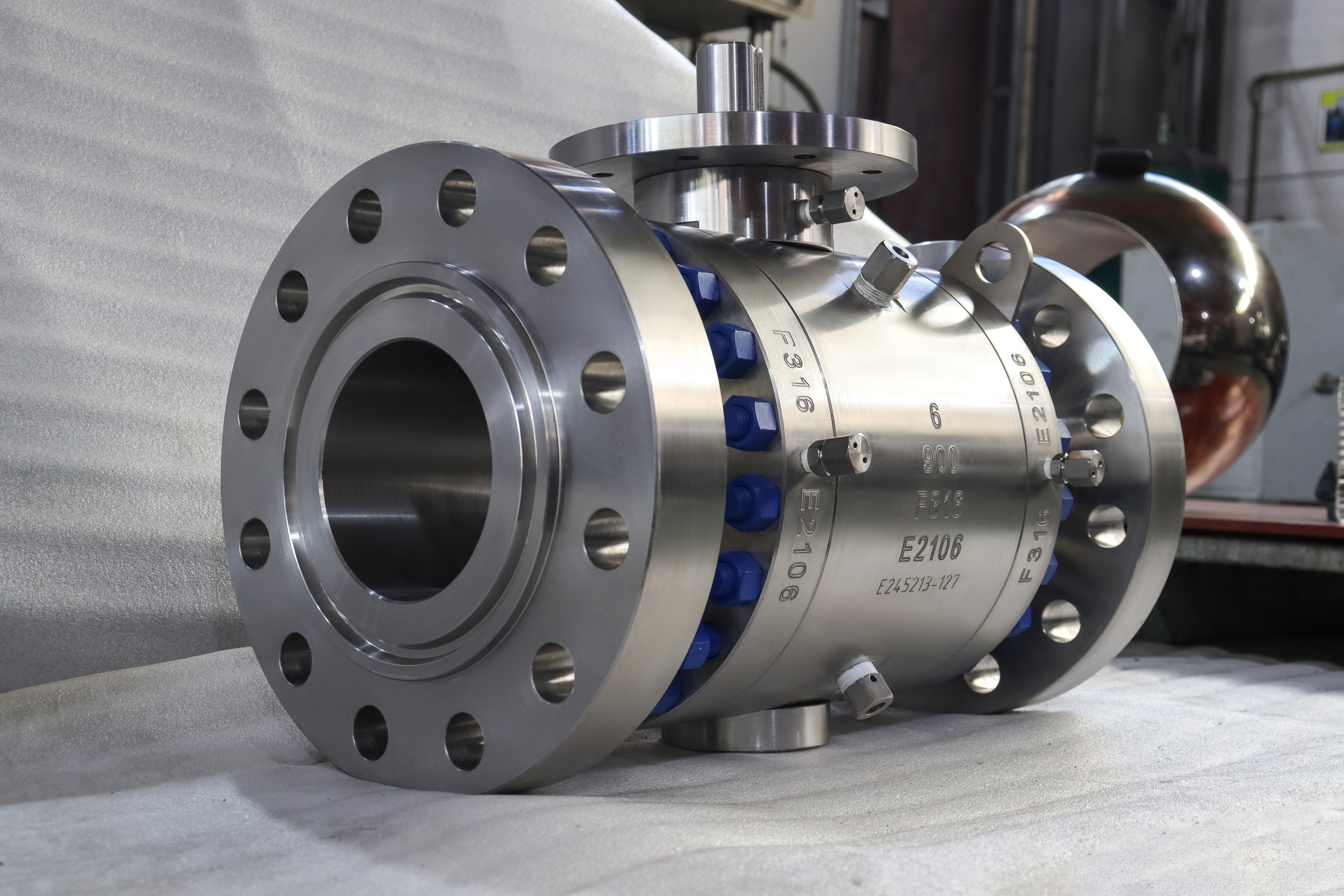
This is a six inch Class 900 trunnion mounted ball valve built in three pieces: a centre section carrying the stem, the packing and both seat pockets, and two end pieces that clamp it between the pipe flanges. The body is F316 stainless, the ball is carried on a trunnion rather than floating, and the seats are spring loaded and self relieving. It is the valve to specify when the line needs to be serviced without being cut.
The three piece layout exists for one reason: the centre section comes out complete. On a two piece valve a seat change means splitting the body and lifting the end cap, which is fine in a workshop but awkward between two flanges that are already bolted to pipe. On this valve the two joints open, the centre drops out with the ball and both seats in it, and the pipe stays where it is.
Design and Construction
The centre section carries everything that wears. Both seat pockets are machined into it from one setting, so the two seats are coaxial by manufacture rather than by assembly, and the ball sits between them without shimming. The stem passes through the top of the centre section and is retained by a shoulder above the packing, so it cannot be ejected with the gland released.
The ball is located by a trunnion at the bottom and the stem at the top, and the seats are pushed onto it by springs. That means the valve seals in both directions independently, the seat load does not rise with line pressure, and the operating torque stays low enough for a lever at six inch Class 900. The seats also relieve, so pressure trapped in the cavity lifts a seat rather than straining the body, which is why no external vent is fitted.

Material Options
F316 is the forged 316 grade, and the reason to use it here rather than a casting is the wall at Class 900: a forging carries the section without the porosity risk that a casting of the same thickness has. A CF8M casting is available at lower classes where the wall is thicker and the risk is lower, and the two are dimensionally interchangeable on this pattern.
The trim is where the money goes. A PTFE seat stops at 150 C, RPTFE at 180 C and PPL at 280 C, so the temperature of the line decides the seat before the pressure does. A hardfaced metal seat reaches the 425 C body limit and is the right choice for steam and for any duty where the soft seat would extrude. The bolting is stainless B8 or B8M because carbon steel studs in a stainless flange corrode at the thread and gall on removal.
| Component | Standard Material | Optional Upgrade | Service Notes |
|---|---|---|---|
| Centre section | ASTM A182 F316 forging | A351 CF8M casting at lower class | Carries the stem, packing and both seat pockets |
| End pieces | ASTM A182 F316 forging | Same heat as the centre where required | Two joints instead of one |
| Ball | F316, hard chrome or ENP | Alternate hardfacing on request | Trunnion mounted, does not travel with pressure |
| Trunnion | Surface hardened F316 | 17-4PH | Takes the seat load on a bearing |
| Stem | 17-4PH | F316 with ENP, 718 for severe service | Blowout proof, keyed to the ball |
| Seat | PTFE or RPTFE | PPL, hardfaced metal | Spring loaded, self relieving |
| Packing | PTFE V rings | Flexible graphite | Adjusted at the gland on the centre section |
| Joint gaskets | Spiral wound, graphite filler | PTFE envelope for clean service | Two per valve, both single use |
| Bolting | A193 B8 or B8M stainless | B7 where the flange is carbon steel | Stainless into stainless galls without lubricant |
| Operator | Lever | Worm gear, actuator | Gear becomes practical above 8 inch |
Technical Specifications
At Class 900 the flange facing changes: ring type joint becomes the normal choice, because a flat gasket at this pressure is pushed outward faster than the bolts can hold it. That is the single most common ordering error on this valve, and it is not visible until the gasket is being fitted. The face to face length follows ASME B16.10 and is held on the drawing rather than inferred.
The bore is full DN150, so the valve adds no restriction and the pressure drop across it is negligible. The temperature band is minus 29 to 425 C for the body, but the assembled valve is limited by whichever seat compound was ordered, and the test pressures scale with the class: shell at one and a half times 900LB and seat at one and a time. The table below is what the valve is built and tested against.
| Item | Value |
|---|---|
| Product type | Three piece flanged trunnion mounted ball valve |
| Nominal size | 6 inch, DN150 |
| Pressure class | Class 900, PN150 in the API 6D designation |
| Body material | ASTM A182 F316 forged stainless, or A351 CF8M cast |
| Body construction | Three piece, two bolted joints, centre section removable |
| Ball support | Trunnion mounted, upper and lower bearing |
| Ball | F316, hard chrome plated or ENP |
| Stem | 17-4PH, F316 with ENP, or 718 where ordered |
| Trunnion | Surface hardened F316 or 17-4PH |
| Seat | PTFE, RPTFE, PPL, or a hardfaced metal seat |
| Seat design | Spring loaded, both seats independently energised |
| Cavity relief | Self relieving through the seat |
| Packing | PTFE V rings, flexible graphite option |
| Body joint gasket | Spiral wound with graphite filler, two joints |
| End connection | Flanged, raised face or ring type joint, ASME B16.5 Class 900 |
| End option | Butt weld ends to ASME B16.25 |
| Face to face | ASME B16.10, held on the drawing |
| Bore | Full port, DN150 through the ball |
| Design standard | ASME B16.34, API 6D, API 608 |
| Test standard | API 598, API 6D |
| Fire safe | API 607 with the seat compound supplied |
| Anti static | Ball to body continuity, measured per valve |
| Temperature range | -29 to 425 C body, ceiling set by the seat |
| Media | Water, process liquid, gas, weak acids, food and pharmaceutical lines |
| Operation | Lever at this size, gear from 8 inch upward |
| Operation option | Pneumatic or electric actuator to ISO 5211 |
| Mounting | ISO 5211 pad on the centre section |
| Service access | Ball and both seats with the centre section out |
| Marking | Size, class, material and heat number on the body |
| Traceability | EN 10204 3.1 certificate with the heat number |
Standards and Compliance
A three piece valve has two pressure boundary joints, and that is the fact the standards care about most here. API 6D treats each joint as part of the pressure envelope, so both are tested and both are documented, and ASME B16.34 sets the wall that both have to carry at Class 900. API 608 then adds the details that do not depend on the joint at all: the anti static path, the blowout proof stem and the nameplate.
The three piece design adds one compliance point that a two piece valve does not have: two pressure boundary joints instead of one, and therefore two gaskets that have to be the right material and correctly torqued. That is a documentation item as much as an engineering one, because a joint gasket that is not on the certificate is a joint that cannot be traced at an audit.
| Requirement | Standard | What J-VALVES Supplies |
|---|---|---|
| Wall and rating | ASME B16.34 | Wall tabulated for Class 900 in austenitic material |
| Valve design | API 6D and API 608 | Pipeline design plus the ball valve specifics |
| Flange drilling | ASME B16.5 Class 900 | Ring type joint is the usual facing at this class |
| Face to face | ASME B16.10 | Length on the signed drawing |
| Pressure test | API 598 | Shell 1.5 times and seat 1.1 times the rating |
| Fire test | API 607 | Certificate against the seat compound |
| Cavity relief | API 6D requirement | Self relieving seat, direction marked |
| Material certificate | EN 10204 3.1 | Heat number traced from the forging |
| Butt weld option | ASME B16.25 | Where the line is welded rather than flanged |
Manufacturing Process
The centre section and the two end pieces are forged from the same grade and machined as a set. The joint faces are cut first, then the three pieces are bolted together and the bore and both seat pockets are cut through the assembly, which guarantees that the bore runs true across both joints. Machining the pieces separately and relying on dowels works, but the tolerance stack is larger than the seat preload can absorb.
The trunnion bore is machined in the same setting as the seat pockets, because a trunnion that is a few hundredths off centre loads the bearing on one side and shows up as a stiff valve rather than as a leak. The flange is drilled last from the ASME B16.5 table for Class 900 at six inch, and the facing is cut to the ring joint groove profile where RTJ is ordered.

Quality Control and Testing
Both joints are tested, not just the body. The shell test is run with the centre section assembled and torqued to the drawing, so that a joint that is going to weep does it on the bench rather than in the plant. A three piece valve has twice the joint area of a two piece one, and the second joint is the one that gets less attention during assembly.
The cavity relief check is specific to the trunnion design and is run before the valve is painted: the cavity is pressurised with the valve closed and the seat is watched for lifting at the designed differential. Torque is measured at the rated pressure and issued with the drawing, because on a six inch Class 900 valve the difference between a comfortable lever and a two handed one is small and the actuator selection depends on the measured figure.
| Step | What Is Checked | Standard or Acceptance |
|---|---|---|
| Chemistry | F316 against the certificate, molybdenum included | Spectrographic analysis per heat |
| Grade identity | F316 against 304 or duplex on the finished body | Positive material identification on every body |
| Joint faces | Flatness of both joint faces | Checked on a surface plate before assembly |
| Shell test | Centre section and both joints | 1.5 times the rating, held to API 598 |
| Seat test | Both directions, both seats | 1.1 times the rating, no visible leakage |
| Cavity relief | Seat lift at the designed differential | Checked on assembly, recorded |
| Torque | Breakaway torque at the rated pressure | Measured, issued with the drawing |
| Anti static | Ball to body continuity | Measured in ohms per valve |
| Centre section fit | Bore alignment across both joints | Checked with the joints closed and torqued |

Applications and Industry Service
The valve is used on process lines in chemical plants, food and pharmaceutical service where a stainless body is required, water systems at high pressure, and gas lines where Class 900 is the specification. Its advantage is the service access: on a skid where the pipe is welded or where breaking a flange is a day of work, taking the centre section out is a two hour job.
It is the wrong valve for chlorides at temperature, where a super austenitic or duplex grade is the answer rather than 316. It is wrong for a line that will be pigged if the seat pockets present a ledge, and it is wrong where the two extra joints are seen as two extra leak paths with no service requirement to justify them.

Installation, Operation and Maintenance
The valve is installed with the flow arrow matching the marked relief direction, and both joints torqued in a cross pattern to the figure on the drawing. On a stainless flange, studs are lubricated before assembly, because dry stainless into stainless galls and a galled stud has to be cut out of a flange that is part of the valve. The valve is not a pipe support.
A seat change is the reason to buy this design. Isolate, drain, open both joints, lift the centre section out, and the ball and both seats are on the bench. Both joint gaskets are replaced, the seat O rings are replaced, and the trunnion bearing is inspected while the centre is out. The packing can be adjusted in service at the gland, but replacing it is a centre section job.
How to Specify and Order
An order needs size, class, material, flange facing, seat compound and the end connection. For this valve that is six inch, Class 900, F316, ring type joint, PTFE seat, flanged. Where the line is welded, butt weld ends to ASME B16.25 replace the flanges and the face to face length is measured over the weld ends instead.
Ask for the material certificate to EN 10204 3.1, the pressure test record covering both joints, the cavity relief check and the measured torque. Spares worth ordering with the valve are a pair of joint gaskets, a seat and O ring kit and a set of packing rings; on a three piece valve the gaskets are the item that stops it being reassembled, and they are cheap.
FAQ
Q: What is the advantage of a three piece trunnion ball valve?
A: The centre section comes out complete with the ball and both seats, so the valve can be serviced without cutting the line or removing the end connections from the pipe. On a welded or hard to reach skid that turns a day of work into a couple of hours, at the cost of a second pressure boundary joint.
Q: Is Class 900 the same as PN150?
A: Yes. API 6D clause 7.2 lists PN150 against Class 900. The valve is marked with the class and flanged to ASME B16.5 Class 900, which at six inch is normally a ring type joint facing rather than a raised face.
Q: Why is a ring type joint used at Class 900?
A: Because a flat gasket is pushed outward by the internal pressure faster than the bolts can hold it at this class. A ring joint confines the gasket in a groove so it cannot be extruded. The facing is not interchangeable with a raised face, and getting it wrong is not visible until the gasket is being fitted.
Q: Does this valve need a cavity relief vent?
A: No. The seats are self relieving, so pressure trapped in the body cavity lifts a seat and escapes to the low pressure side. That is an API 6D requirement for this design and the relief direction is marked on the body.
Q: Can the seats be replaced without removing the valve from the line?
A: The centre section can be taken out with the end pieces left bolted to the pipe, which is as close as a flanged valve gets. The line still has to be isolated, drained and vented first, and both joint gaskets are replaced when it goes back together.
Q: What temperature can this valve take?
A: The body is rated from minus 29 to 425 C, but the assembled valve is limited by the seat. PTFE stops at 150 C, RPTFE at 180 C, PPL at 280 C, and only a hardfaced metal seat reaches the 425 C body limit. Order by the operating temperature rather than by the body rating.


Hot Products


News
Ball Valves in Geothermal Brine: Silica Scale, Chloride Cracking And The Cooling Trap
Why geothermal brine destroys ball valves: retrograde silica scale, calcite at the flash point, chloride cracking above 60 C and the 250 C seat limit.
Read More
Ball Valve Face To Face Dimensions: Why A Correctly Ordered Replacement Still Does Not Fit
A 6 inch Class 150 ball valve can be 267 or 305 mm face to face and both are compliant. How B16.10, EN 558 and flange drilling decide whether it fits.
Read More
Ball Valve Stem Key And Keyway: What Gives Way First, And What The Handle Cannot Tell You
Between the handle and the ball there are four fits. Which one shears, which one cracks, and how a few degrees of lost motion hides a valve that never seated.
Read More
Ball Valve Datasheet: Six Blocks That Decide Whether Two Quotes Are Comparable
A ball valve datasheet only works when six blocks are fixed: pressure basis, bore, temperature ceiling, test, end connection, operator. How each is written.
Read More