


CHINA J-VALVES Offers Various High-quality I ndustrial Ball Valves
J-VALVES, a distinguished professional ball valve manufacturer rooted in China, takes pride in its extensive product portfolio. Our offerings span a wide range, including trunnion-mounted ball valves, floating ball valves, high-temperature ball valves, high-pressure ball valves, metal-sealed ball valves, ultra-low temperature ball valves, DBB ball valves, Three-way And Four-way Ball Valve, and fully welded ball valves. Each product is a testament to our commitment to precision engineering and reliable performance. Meticulously crafted, they are designed to not only meet but exceed the most stringent industrial demands, ensuring stable operation even under extreme conditions. This enables us to provide our clients with high-value services and makes our valves widely sought-after in industries.
Product Category
Contact Us


-
J-VALVES-Q47F
-
J-VALVES
Overview of the J-VALVES Thirty Inch PN150 Large Bore Three Piece Trunnion Ball Valve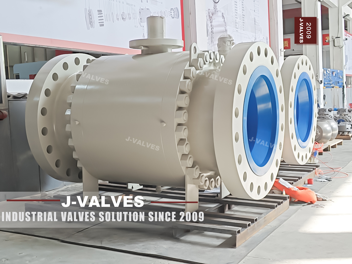
This is a three piece trunnion mounted ball valve at thirty inch, Class 900, with ring joint flanged ends, a bare stem on a machined mounting pad and two steel legs welded under the body. The ball is full bore, so the flow path through the valve is thirty inch like the pipe it sits in. Two facts about this size are missing from most data sheets, including the one this page replaces. The first is that ASME B16.5 stops at NPS 24, so a thirty inch flange is not a B16.5 flange at all; it comes from ASME B16.47, which is published in two series that do not interchange.
The second is that a body this size is normally a casting or a fabrication rather than a single forging, whatever grade is printed in the material row. The legs are the third fact, and they are visible in every photograph of the valve. At this size the valve is a structural item in the piping system: its weight goes into steel, its centre of gravity goes into the stress analysis, and the flange bolts are there to seal rather than to carry. Large bore exists for two reasons and neither of them is pressure.
A full bore valve passes a pig, so a line can be cleaned and inspected without being cut, and a large port keeps the velocity down at the flow the line was designed for. Both are pipeline arguments rather than process arguments, which is why a valve this size is specified by the transmission engineer and bought against a line class rather than against a differential pressure. The money in it sits in the flange and in the mass of metal, not in the trim.
Design and Construction
Three pieces at this size means a centre body weighing as much as a small vehicle and two end caps that come off along the pipe axis. The ball, both seats and both trunnion bearings stay in the centre section, which is the only reason the two bearing bores can be machined in one setup and keep their alignment after a rebuild. The trunnion arrangement is what makes a thirty inch valve operable at all. The shafts carry the ball, so the seat load comes from the seat springs and the pressure, not from the ball being pushed downstream.
Without that, the torque at this diameter and this class would be beyond any hand operator and most actuators. The legs are welded to the lower body and are the interface with the structure, not with the pipe. The top of the valve is a machined pad with a bare stem: no gearbox and no lever are fitted in the standard build, because the operator at this size is a project decision that depends on the torque measured on the finished valve.
The end caps staying on the pipe flanges is the whole point of the design, and it is also a load case the pipe support has to be checked for. With the centre section lifted out, the caps are still bolted to the line, cantilevered, and heavier than anything the support saw during installation. A support designed for the assembled valve can be marginal in that condition. That is a question for the piping designer rather than the valve supplier, and it is worth raising before the support is detailed rather than after.

Material Options
The material row is where the product form question has to be settled. A105 is a forging grade; a thirty inch body is usually cast or fabricated, and the certificate should say which, because the two have different defect spectra and different inspection. The seat deserves the sentence it usually does not get. PEEK is a capable material and it is the standard here, but a PEEK seat carries a permitted leakage rate rather than a bubble tight claim, and at Class 900 the leakage acceptance is the thing a buyer should be reading rather than the pressure number.
At this bore the ball is heavy, and the trunnion is what makes the valve operable at all: the shafts take the load so the seats only have to seal. The consequence for the order is that the operator is a project decision rather than an accessory. Turning torque scales with the bore and with the seat load, it is measured on the finished valve, and a gearbox or an actuator chosen from a catalogue figure is chosen for a valve that may not be the one delivered. The correct sequence is the valve, then the measurement, then the operator.
The seat arrangement at this bore is a decision with a consequence that is easy to miss. A double piston effect seat seals in both directions and cannot relieve the cavity, so trapped liquid that warms has nowhere to go; a single piston seat relieves upstream and gives up the second barrier. Both are legitimate and both are ordered by name. What is not legitimate is to offer piston seats on a page and leave the relief question to be discovered at commissioning, because by then the seats are made.
| Component | Standard Material | Optional Upgrade | Service Notes |
|---|---|---|---|
| Body and end caps | A105 forging as ordered | A216 WCB casting, A350 LF2 for low temperature | Product form must be named on the certificate at this size |
| Ball | A105 with ENP or hard chrome | Solid F316, or tungsten carbide HVOF | Coated carbon ball and solid stainless ball are different valves |
| Trunnion shafts | Surface hardened A105 or 17-4PH | Nickel based alloy for high temperature | Shaft load at this size is the design driver |
| Stem | 17-4PH precipitation hardening | Nickel based alloy | Hardness limit under NACE MR0175 in sour service |
| Seat | PEEK | Metal seat with flexible graphite, or carbide faced | Seat choice sets both temperature and leakage acceptance |
| Packing | Flexible graphite with wire reinforcement | Pure graphite braided | Graphite is the default at this class, not an upgrade |
| Gasket | Ring joint gasket, octagonal or oval | Soft iron, low carbon steel, or F316 per the duty | RTJ only; there is no flat gasket option at this size |
| Bolting | A193 B7 or B7M with A194 2H or 2HM | B8M with 8M nuts for corrosive duty | B7M and 2HM for sour service |
Technical Specifications
The table below states the size, the class and the flange standard separately, because at NPS 30 they no longer follow from one another. The flange table changes at this diameter, and the series has to be named on the order. The flange row is the one to take to a meeting. Two valves can both be described as thirty inch Class 900 ring joint and still not bolt to the same pipe, because B16.47 series A and series B differ in outside diameter, bolt circle, bolt count and bolt size at the same nominal size and class.
A quote that does not name the series is a quote that has not been finished. The face to face row is deliberately not a standard number. Where the size and class are tabulated, the table applies; where they are not, the length is a drawing dimension and both parties have to agree it before the pipe is cut. Three numbers a buyer will look for are deliberately not in the table.
There is no mass, no lifting point coordinate and no operating torque, because all three depend on the body product form, the trim ordered and the seat type, and all three are measured on the finished valve. On a valve this size that is not academic: the mass decides the crane, the lifting points decide the sling, and the torque decides the operator. All three are on the signed general arrangement drawing rather than on a web page.
| Item | Value |
|---|---|
| Type | Three piece trunnion mounted ball valve, side entry |
| Nominal size | 30 inch, DN750, full bore |
| Pressure class | Class 900 |
| Pressure designation | PN 150, the designation API 6D clause 7.2 writes against Class 900 |
| Shell rating | ASME B16.34 at Class 900, read at design temperature |
| Body material | A105 as ordered; product form stated on the certificate |
| End connection | Ring joint flanged to ASME B16.47, series named on the order |
| Flange note | ASME B16.5 stops at NPS 24, so no B16.5 flange exists at this size |
| Face to face | On the signed drawing; B16.10 tabulated only where the size and class are listed |
| Trunnion | Upper driven shaft, lower locating shaft in a bolted bottom cover |
| Support | Two steel legs welded under the body |
| Operator interface | Bare stem on a machined mounting pad |
| Temperature, body | Per the material group of the grade supplied |
| Temperature, valve | Set by the seat and the packing ordered |
| Product standard | API 6D with ASME B16.34 for the pressure boundary |
| Test standard | API 598 and API 6D |
| Fire test | API 607 and ISO 10497 when specified |
Standards and Compliance
Compliance at this size is mostly about scope. API 6D applies and ASME B16.34 governs the pressure boundary, while API 608 does not reach Class 900 at any size and the flange standard is not the one printed on the original sheet. The ring joint deserves one line of its own, because it is the only part of a flanged joint that is bought separately. The groove is machined into the valve flange and the ring is a consumable that arrives with the pipe, and the ring number has to match the groove.
That is a conversation to have at order rather than at site. The legs are structural welds on a pressure part, and that combination is what makes them a documentation item rather than a workshop detail. The welding procedure has to be qualified, the welders qualified to it, and the examination of the welds recorded; where the wall and the material call for it, stress relief follows welding. Where the purchaser's specification calls for it, the examination is witnessed, and the acceptance criterion is written into the order rather than left to the works.
None of that appears on a certificate of material, so a valve can arrive with a correct 3.1 certificate and no evidence that the parts holding it up were welded to a procedure anybody approved. Fire qualification is the row that says band rather than valve. API 607 is a type test on a representative valve, so at thirty inch the band the certificate was qualified on has to cover this size and class, and a certificate written for a six inch valve is not automatically evidence for this one. The difference is invisible unless somebody reads the scope printed on it.
| Requirement | Standard | What J-VALVES Supplies |
|---|---|---|
| Pressure boundary design | ASME B16.34 | Wall thickness and material group on the drawing |
| Product standard | API 6D | Design, marking and documentation to the pipeline valve standard |
| Product standard, note | API 608 does not apply | Flanged scope stops at Class 600, this valve is Class 900 |
| Flange drilling | ASME B16.47 | Series named on the drawing and on the order |
| Ring joint detail | ASME B16.20 | Ring groove dimensions and ring type agreed at order |
| Pressure testing | API 598 and API 6D | Shell at 1.5 times rating, seat at 1.1 times rating |
| Fire qualification | API 607 and ISO 10497 | Certificate covering the size and class band ordered |
| Material certification | EN 10204 3.1 | Grade and product form named, heat numbers on all pressure parts |
Manufacturing Process
At this size the body is a casting or a fabrication rather than a single forging, and the drawing says which. Either way the machining sequence starts with the body joint faces and the two trunnion bores in one setup, because everything downstream depends on those three features being square to each other. The legs are welded after the body is machined and before the coating, with the weld procedure and the inspection agreed at order. A leg welded after coating is a leg with a bare patch around it, and that patch is where the paint system fails first. Assembly of a valve this size is a lifting job.
The ball is set on the lower trunnion, the seats are fitted, the caps are closed and the joint bolts are tensioned in a controlled sequence. The valve is then turned through a quarter turn under pressure with the actuator or the gearbox fitted, and the torque recorded. Whether the body is cast or fabricated at this size is a real choice with different consequences, and the certificate should say which was supplied. A casting needs a pattern, a sound wall and a repair policy; a fabrication needs a weld map, qualified procedures and post weld treatment. Both are legitimate, and the buyer is entitled to know which one is in the crate, because the inspection route and the repair options differ.
A data sheet that names the grade and stops there has not answered the question. Not every machine shop can bore and face a body this size, and that is a delivery question disguised as a technical one. The body has to be set up so that both joint faces and both trunnion bores are cut without losing the alignment between them, which needs a machine and a fixture rather than a big lathe and patience. It is worth asking where that operation is done, because a body that has been machined in two setups can be within every individual tolerance and still put the ball axis out of square to the joints.

Quality Control and Testing
The sequence below is the same as for a smaller trunnion valve with three additions that this size forces: a dimensional record of the flange rather than a go and no go check, an inspection of the leg welds, and a hydrostatic test whose duration and water volume are planned rather than improvised. The flange record is the step that saves the most money. Measuring the outside diameter, the bolt circle and the bolt count on the finished valve and writing them on a sheet takes minutes, and it catches a series mismatch before the valve is on a ship rather than after it is on a jetty.
Test volume changes the test rather than the standard. A body this size takes time to fill, to bring to pressure and to drain, and the reading at the end of a short hold says less than it would on a small valve, because a small leak moves the needle slowly against a large volume. The answer is a hold long enough for the drop to mean something, recorded with start and end readings rather than a tick in a box.
The shell test covers the body, both joints, the bottom cover and the leg welds, and the legs are the part most often left out, because they are not the pressure boundary and yet they are welded to it. The body is drained and dried as soon as the test is over, since a wet carbon steel cavity will flash rust before the paint goes on and no coating will hold over it.
| Step | What Is Checked | Standard or Acceptance |
|---|---|---|
| 1 Incoming material | Grade, product form, heat identity | Certificate matches the stamping, form named |
| 2 Body dimensional | Bore, joint faces, trunnion bores, leg positions | Drawing, all features recorded |
| 3 Flange record | Outside diameter, bolt circle, bolt count, ring groove | ASME B16.47 series named on the order |
| 4 Leg welds | Weld procedure, visual, and the inspection agreed | Project specification for the weld class |
| 5 Shell test | Body, two body joints, bottom cover | API 598, 1.5 times rating, no leakage |
| 6 Seat test | Both seats, both directions | API 598, 1.1 times rating, acceptance per seat type |
| 7 Operating test | Quarter turn under pressure, torque recorded | Full travel, no ball lift, torque on the record |
| 8 Records | Stamping, heat traceability, dimensional and test sheets | Document pack issued with the valve |

Applications and Industry Service
Large bore high pressure isolation is the duty: transmission and station piping, high pressure gas headers, produced water and injection manifolds, and the mainline block valves on a large line where the size is dictated by throughput rather than by the branch. Because the bore is full, this valve can pass a pig, which is a real difference from the reduced bore valves in the same range. If the line will ever be cleaned, gauged or inspected by a tool, the full bore is not a preference, it is a requirement, and it has to be ordered as such. What it does not do is worth stating.
It is an isolation valve and not a control valve, throttling on a PEEK or metal seat will damage the seating surfaces, and a valve this size should not be ordered without deciding how it will be operated and how it will be lifted. Duties at this size are transmission and storage rather than process: gas and liquid pipelines, pump station suction and discharge headers, tank farm manifolds, and the isolation points either side of a metering or regulating station. In all of them the valve stands fully open or fully closed for years at a time, and pigging is written into the pipeline specification rather than offered as an option.
The other requirement that appears here and not below is structural: the valve enters the pipe stress model with a mass and a centre of gravity, and the support design follows from that. Three smaller valves are sometimes proposed against one valve this size, and the comparison is not only about price. Three valves give isolation in steps and a measure of redundancy; one valve gives a single full bore path for a pig and one set of flanges to leak. What decides it is usually the pigging requirement and the space, because a pig run cannot step down through three bodies, and a station with three large valves needs three times the support steel. That is a piping layout question, and it belongs in the enquiry rather than in the valve specification.

Installation, Operation and Maintenance
Set the valve on its legs and shim them until the flange faces are parallel to the pipe flanges before any bolt is tightened. The legs carry the weight and the bolts seal the joint; doing it the other way round puts the weight into the bolts and the bending into the body joints, and that shows up later as a joint that weeps after the first thermal cycle. Lifting points are the body, never the gearbox, the stem or the mounting pad. A thirty inch valve swung from its stem is a bent stem and a scrapped actuator interface. Plan the lift with the centre of gravity from the drawing rather than with a sling around whatever looks convenient.
Maintenance above the body is limited to the stem packing, which can be adjusted with the line under pressure once the cavity is vented. Everything else needs the valve isolated and drained: the end caps, the seats, the ball and the bottom cover are all pressure boundary items, and the cavity volume at this size holds a lot of liquid. The installation is a rigging sequence before it is a piping one. Set the valve on its legs, shim to the structure, and only then bring the flange bolts up, so the weight is carried by steel and the bolts do what they were designed for.
Lift on the body with slings rated for the load and never on the stem, the lever boss or the pad, because those parts are sized for torque rather than for weight. A valve this size dropped once is a valve that will not hold, whatever the test sheet said before it fell. Two things make the first installation different from every later one: the shims and the record of them. Shim packs under the legs are what actually carry the valve, and if nobody writes down what was used, the next person to lift the valve out puts it back on a different stack and the flange bolts take a load they were never meant to take. Photographing the stack before the bolts go in is the cheapest reliability measure on the site.
How to Specify and Order
Six fields decide the valve and four of them are unusual at this size. Size and bore, full or reduced. Class and flange standard, with the B16.47 series named. Ring type and gasket material. Body product form, forging, casting or fabrication, because the certificate has to match it. Seat type, which fixes the leakage acceptance. And the operator package, with the mounting pad size, the stem dimensions and whether a gearbox or an actuator is fitted.
The documents to ask for by name are the EN 10204 3.1 certificate with the product form stated, the API 598 and API 6D test records with the operating torque, the fire certificate for the size and class band, the weld procedure and inspection record for the legs, and the general arrangement drawing with the leg height, the lifting points and the face to face length. At this size the drawing is the specification. The enquiry should carry five things beyond the size and class: the B16.47 series, the facing and its groove, the face to face agreed for the drawing, the leg height and the lifting points, and the operator interface.
Every one of them is a drawing item rather than a catalogue item, and every one of them is cheaper to settle at the bid stage than after the castings are made. The general arrangement drawing is the specification at this size, and the purchase order should say so. Where the buyer and the works will disagree later is almost always the length. The face to face is a drawing item at this size, so there is no table to appeal to, and two drawings that were approved at different revisions can both be genuine. Keeping the approved revision number on the purchase order, and quoting it in the certificate pack, is the cheapest form of protection available. It costs a line of text and it settles the argument before it starts.
FAQ
Q: Why is the flange not ASME B16.5 at thirty inch?
A: Because B16.5 stops at NPS 24. A thirty inch flange comes from ASME B16.47, which is published in series A and series B, and the two differ in outside diameter, bolt circle, bolt count and bolt size at the same size and class.
Q: What does 30 x 30 inch mean?
A: Both numbers are thirty inch, so the valve is full bore rather than reduced. A reduced bore would be written as a pair of different sizes, and the flanges would still follow the larger one.
Q: Is the body a forging?
A: The grade is A105 as ordered, and the product form has to be named on the certificate. At this size the body is normally a casting or a fabrication, so the certificate should say which rather than leave it to be inferred from the grade.
Q: Why does the valve have legs?
A: Because at thirty inch the valve is a structural item. The legs carry the weight into the structure so the flange bolts only have to seal, and the centre of gravity goes into the pipe stress model rather than being hung on the flanges.
Q: Does API 608 apply at Class 900?
A: No. API 608 covers flanged valves to Class 600, so no size at Class 900 falls inside it. The product standard here is API 6D, with ASME B16.34 for the pressure boundary.
Q: Can this valve pass a pig?
A: Yes, because the bore is full. That is a real difference from the reduced bore valves in the same range, and it is the reason a line that will be cleaned or inspected needs the full bore written into the order.


Hot Products


News
Ball Valves in Geothermal Brine: Silica Scale, Chloride Cracking And The Cooling Trap
Why geothermal brine destroys ball valves: retrograde silica scale, calcite at the flash point, chloride cracking above 60 C and the 250 C seat limit.
Read More
Ball Valve Face To Face Dimensions: Why A Correctly Ordered Replacement Still Does Not Fit
A 6 inch Class 150 ball valve can be 267 or 305 mm face to face and both are compliant. How B16.10, EN 558 and flange drilling decide whether it fits.
Read More
Ball Valve Stem Key And Keyway: What Gives Way First, And What The Handle Cannot Tell You
Between the handle and the ball there are four fits. Which one shears, which one cracks, and how a few degrees of lost motion hides a valve that never seated.
Read More
Ball Valve Datasheet: Six Blocks That Decide Whether Two Quotes Are Comparable
A ball valve datasheet only works when six blocks are fixed: pressure basis, bore, temperature ceiling, test, end connection, operator. How each is written.
Read More