


CHINA J-VALVES Offers Various High-quality I ndustrial Ball Valves
J-VALVES, a distinguished professional ball valve manufacturer rooted in China, takes pride in its extensive product portfolio. Our offerings span a wide range, including trunnion-mounted ball valves, floating ball valves, high-temperature ball valves, high-pressure ball valves, metal-sealed ball valves, ultra-low temperature ball valves, DBB ball valves, Three-way And Four-way Ball Valve, and fully welded ball valves. Each product is a testament to our commitment to precision engineering and reliable performance. Meticulously crafted, they are designed to not only meet but exceed the most stringent industrial demands, ensuring stable operation even under extreme conditions. This enables us to provide our clients with high-value services and makes our valves widely sought-after in industries.
Product Category
Contact Us

-
J-VALVES-Q347F
-
J-VALVES
Overview of the J-VALVES 8" PN420 F11 High Pressure High Temperature Flange Ball Valve
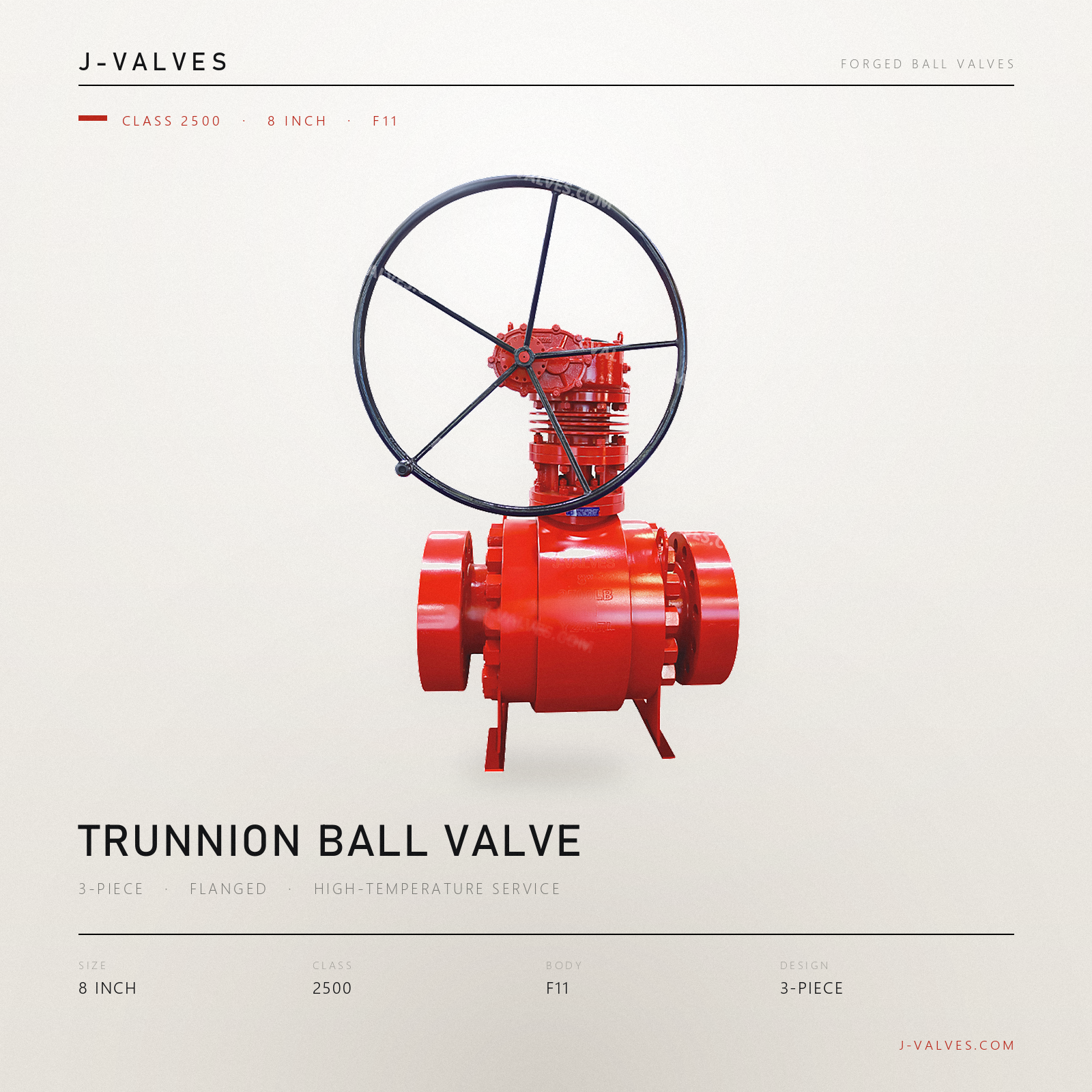
This is a three piece side entry trunnion mounted ball valve in NPS 8, Class 2500, with a forged 1.25Cr-0.5Mo body and ring joint flanged ends. The plate on the body reads 8, 2500LB and F11, with a serial number below. PN 420 is the same rating written the way API 6D clause 7.2 writes it, so the title of this page and the stamp on the valve describe one valve, not two. It is built for steam, hydrocarbon and hydrogen lines that run hot enough that carbon steel has already run out of allowable stress.
The chrome moly body is the reason this valve exists, and it is the one thing the original listing gets backwards. F11 sits in ASME B16.34 group 2.1, which runs from -29 °C to 593 °C. Carbon steel sits in group 1.1, where the standard carries a note that above 425 °C the carbide phase can convert to graphite. The listing prints -29 °C to +425 °C as the range for F11, which is the carbon steel number, and then writes in the description that the body suits service above 540 °C. Both sentences are on the same page.
Three things on that page need separating before anything else can be discussed: the temperature range, the list of design standards, and the menu of seat options. Each of them is contradicted by another line on the same page, and the contradictions do not point in one direction. The temperature line understates what the body can do, so it costs sales rather than safety. The standards block overstates what has been certified, which is the more serious of the two. The seat menu contradicts the standards block in the same paragraph.
Design and Construction
The body is split into three pieces, a centre section and two end closures, so there are two bolted body joints on the pressure boundary of a Class 2500 valve. Each joint carries its own gasket and its own ring of heavy studs. At this rating the studs are large and the preload is high, and the two joints are the parts of the valve most likely to weep after a few thermal cycles. A three piece body is chosen for access to the ball and seats, and this is what that choice costs in a valve this size.
The ball is carried on upper and lower trunnions. From NPS 6 upward the two trunnions run in separate bearing blocks rather than in the primary body, and at NPS 8 this is the arrangement in use. The thrust from line pressure goes into the bearings, not the stem, which is why an operator with a handwheel can move the valve at all. The trunnions rotate in metal backed self-lubricating bearings, and the stem is separate from the ball so that it carries no side load from the pressure acting on the closed ball. That separation also makes the anti blow out feature meaningful: the stem is retained by the body cover, so cavity pressure cannot push it out even with the gland removed for repacking.
Above the body the bonnet is extended, and the extension carries a stack of four thin discs that act as cooling fins. The photograph shows them plainly between the gland area and the gearbox, and the original listing never mentions them, offering extended bonnets only as an option for cryogenic or high temperature service. Their job is to interrupt the path that heat takes up the stem, so that the packing, the gearbox grease and the handwheel sit at a temperature the materials there can tolerate. On a valve rated to 593 °C this is not decoration.

Material Options
A182 F11 is a forged low alloy steel with 1.00 to 1.50 percent chromium and 0.44 to 0.65 percent molybdenum, supplied normalized and tempered. The chromium gives it oxidation resistance and the molybdenum gives it creep strength, and the combination is what holds allowable stress at temperatures where plain carbon steel has none left. It is not a stainless steel: it will not survive a wet chloride environment, and it is not the right answer for a line that is hot but not very hot. F22 takes over where F11 runs out, and the two belong to the same family. Between them they cover the high temperature band up to 593 °C, so the choice between F11 and F22 is made on creep margin rather than corrosion.
The ball, seat rings and stem are inside the valve and no photograph resolves them. The listing names specific hard facing products and specific high temperature alloys for these parts, and those names are trade names rather than standard designations. What the page can state is the class of material: a cobalt based hard facing on the seating surfaces, and a precipitation hardening or nickel based alloy for the stem. The actual grade belongs on the EN 10204 3.1 certificate, matched to the heat number stamped beside F11.
Body joint bolting on a high temperature valve is a material decision of its own. A193 B16 is a chromium molybdenum vanadium steel made for flanged joints that operate hot, and it is the usual choice above the range where B7 starts to relax. Bolting relaxes under sustained temperature and load even when it is correct, which is why the joint needs a hot re-torque after the first heat up. The ring gasket is a B16.20 metal ring, octagonal or oval, in soft iron or low alloy depending on the line.
| Component | Standard Material | Optional Upgrade | Service Notes |
|---|---|---|---|
| Body and bonnet | ASTM A182 F11 (1.25Cr-0.5Mo) forging, normalized and tempered | A182 F22 where the design temperature passes the F11 ceiling | Plate reads F11; class as certified |
| Ball | Corrosion resistant alloy, hard faced | Alternative facing per order | Inside the cavity, not resolved by the photograph |
| Seat ring | Metal seat, hard faced and lapped to its own ball | Soft seat only below the packing limit | Matched pair, do not interchange |
| Stem | High temperature alloy, anti blow out, retained by the body cover | — | Gland renewable with the valve in line |
| Trunnion bearings | Metal backed self-lubricating | — | Two separate bearing blocks at this size |
| Body joint bolting | ASTM A193 B16 | — | Relaxes at temperature, hot re-torque after first heat up |
| Ring joint gasket | Soft iron or low alloy ring, ASME B16.20 | — | Groove form matters as much as the ring |
| Packing | Flexible graphite, live loaded | Inhibited grade for oxidising service | Oxidises above 450 °C in air |
| End connection | RTJ flanged to ASME B16.5, Class 2500 | — | No EN 1092-1 flange exists at this rating |
Technical Specifications
The size and class pair fixes most of the geometry. NPS 8 at Class 2500 is comfortably inside ASME B16.5, which covers Class 2500 up to NPS 12, so every dimension of both end flanges can be looked up rather than calculated. That matters more than it sounds: at NPS 14 and above there is no published Class 2500 flange dimension in B16.5 or B16.47, and the flanges must be designed rather than selected. B16.47 starts at NPS 26 and carries no Class 2500 row. Face to face follows ASME B16.10, and the ring groove follows B16.20. The RTJ designation is worth stating explicitly on the enquiry, because a raised face flange in the same size and class is a different end preparation and cannot be substituted late in the order without re-machining both ends.
PN 420 appears next to Class 2500 because API 6D clause 7.2 lists them as one row of one table. The practical consequence is that there is no European flange at this level: EN 1092-1 stops at PN 400, so a PN 400 flange cannot be bolted to this valve and will not be offered as an equivalent. A supplier who quotes a PN 400 counterpart is quoting a flange with a different bolt circle, a different bolt count and a different thickness. The mating flange on the line side has to be an ASME B16.5 Class 2500 flange with a matching ring groove.
Operating torque, flow coefficient, mass and overall length in millimetres are deliberately absent. Each of them depends on the seat type, the differential pressure, the hard facing actually applied and the temperature, and none of those are fixed until the order is. Quoting a number before the trim is settled produces an actuator that is undersized in one direction or a support that is wrong in the other. These values are measured on the assembled valve and issued with the signed general arrangement drawing, which is also the document the piping stress analysis needs.
| Item | Value |
|---|---|
| Size | NPS 8, DN 200 |
| Pressure class | Class 2500 |
| Pressure designation | PN 420, the Class 2500 row of API 6D clause 7.2 |
| Body material | ASTM A182 F11 (1.25Cr-0.5Mo) forging |
| B16.34 group | Group 2.1, -29 °C to +593 °C |
| Body construction | Three piece, side entry, two bolted body joints |
| Ball support | Trunnion mounted, upper and lower, two bearing blocks |
| Bore | Full bore |
| End connection | RTJ flanged, ASME B16.5 |
| Ring groove | ASME B16.20 |
| Face to face | ASME B16.10, value from the signed drawing |
| Temperature, body | -29 °C to +593 °C per B16.34 group 2.1 |
| Temperature, packing | +450 °C in oxidising service, inhibited grade above |
| Design standard | API 6D and ASME B16.34 |
| Test standard | API 598 |
| Operator | Worm gear with handwheel |
Standards and Compliance
ASME B16.34 is the document that decides what this valve may be used for. F11 is listed in group 2.1, with a temperature range of -29 °C to 593 °C, and the allowable pressure falls as temperature rises across that range. The same standard places carbon steel in group 1.1 with a 425 °C note about graphitisation, which is the boundary that makes F11 worth its price. Reading a group 1.1 rating against an F11 body is the most common error in high temperature valve procurement, and it is the error this listing makes in print. The two groups do not share a rating curve at any temperature above 425 °C, and the gap between them widens as the temperature climbs toward the F11 ceiling.
API 6D applies and is the design and testing reference for this valve. API 608 does not apply, for two independent reasons. Its flanged scope stops at Class 600, so Class 2500 is outside it before size is considered, and clause 1.7 places trunnion valves fitted with double piston effect seats outside the standard altogether. The listing cites API 608 and then offers double piston seats in its own seat table, which is a citation that excludes the preferred option on the same page.
Three more items on that page are not licences for this valve at all. API 6DSS is the subsea pipeline specification and API 6A PSL 4 is a wellhead specification, and neither describes a ring joint flanged valve for a land based steam or process line. The pressure class block also lists API 2000 to 15000, which are wellhead working pressures from a different standard family and have no meaning for a Class 2500 flanged valve. A buyer who checks any of these against the API monogram directory will not find this valve under them.
| Requirement | Standard | What J-VALVES Supplies |
|---|---|---|
| Shell rating at temperature | ASME B16.34 group 2.1 | Rating applied per grade, not one range shared by the family |
| Product design and marking | API 6D | Design, marking and documentation to API 6D |
| Pressure test | API 598 | Shell at 1.5 times and seat at 1.1 times rated pressure, ambient |
| Flange dimensions | ASME B16.5, Class 2500 | Both end flanges to B16.5 in NPS 8 |
| Ring joint groove | ASME B16.20 | Groove machined to profile and recorded as a dimension |
| Face to face | ASME B16.10 | Dimension stated on the signed drawing |
| Material certificate | EN 10204 3.1 | Certificate matched to the heat number on the plate |
| Fire test | API 607 on request | Tested configuration stated on the certificate |
| Not applicable | API 608, 6DSS, 6A PSL 4 | Not claimed, because none of the three covers this valve |
Manufacturing Process
The body pieces start as forgings rather than castings, which is normal at Class 2500 where section thickness and soundness both matter. Each piece is normalized and tempered to develop the creep properties the grade is bought for, and the heat treatment is recorded against the heat number that later appears on the plate. Machining follows heat treatment, because a forged and tempered piece moves, and a body joint face that is cut before the final temper will not stay flat once it has been through the furnace.
Seat pockets and the stem bore are weld overlaid with a cobalt based hard facing. On a metal seated valve at this rating the overlay is a structural element: it has to resist galling through repeated seating at full differential and it has to be repairable, because replacing a body is not an option. Preheating before overlay and post weld heat treatment afterwards are both required on 1.25Cr-0.5Mo, and the heat treatment is what restores the heat affected zone rather than simply relieving it.
The dimensional work decides whether the valve seals. The ring groove is machined to the B16.20 profile, and a groove that is slightly out of form will seal in the shop and weep after the first thermal cycle. Both body joint faces are machined for flatness and checked for parallelism, the two end flanges are checked for concentricity with the bore, and the stud holes are checked for position because a bolt that has to be forced into its hole cannot be brought to the specified preload. All of these are dimensional records rather than visual inspections, and each one is tied to the serial number of the valve rather than to the batch it came from.

Quality Control and Testing
Every valve gets a shell test and a seat test to API 598, with the shell at one and a half times the rated pressure and the seat at one and one tenth. Both are done at ambient temperature and both are recorded against the serial number. A valve that passes these tests is sound as a pressure vessel, which is a real result at Class 2500. It is not proof that the valve will seal at 540 °C, and the difference between those two statements is where most high temperature surprises come from. The test pressure is derived from the ambient rating of the class, not the rating at design temperature, which is why the figure on the certificate can look generous beside the operating pressure.
The reason is that a metal seat at temperature changes shape. The ball grows, the seat ring grows, the body grows, and they do not grow by the same amount, so the interference that produced a tight seal at 20 °C is a different interference at 540 °C. That is why the clearance between seat and ball is set from the design temperature and why the hard facing has to tolerate the resulting contact stress. The only ways to verify it are a hot test on the assembled valve or a design already proven at that temperature.
Documentation for this valve runs alongside the tests. The 3.1 certificate ties the F11 plate to the heat number and reports chemistry and mechanical properties, positive material identification confirms the alloy actually poured, hardness is recorded on the weld overlay, and the ring groove profile is recorded as a dimension rather than as a pass or fail. The drawing carries the mass, the centre of gravity and the dimensions this page does not print, and those are the numbers the installation is designed around.
| Step | What Is Checked | Standard or Acceptance |
|---|---|---|
| Incoming material | Chemistry and mechanical properties against the heat number | EN 10204 3.1 certificate |
| Alloy identification | Body grade and overlay alloy | Matches the grade stamped on the plate |
| Overlay hardness | Seat pocket and stem bore | Value recorded on the drawing |
| Ring groove profile | Groove form, depth and width | ASME B16.20 profile |
| Body joint faces | Flatness and parallelism | Drawing tolerance |
| End flange alignment | Concentricity with the bore, stud hole position | ASME B16.5 |
| Shell test | Body and both joints | API 598, 1.5 times rated, ambient |
| Seat test | Both seats, both directions | API 598, 1.1 times rated, ambient |
| Final marking | Plate data against the certificate | Grade, class, size and heat number agree |

Applications and Industry Service
The main application is superheated and saturated steam in power generation, where the line runs between roughly 450 °C and the F11 ceiling and where the pressure class is high enough that carbon steel has no allowable stress left. Main steam isolation, high pressure bypass and boiler outlet service all sit in that window. The same valve appears in refinery hydroprocessing, where the combination of temperature, pressure and hydrogen partial pressure rules out carbon steel entirely, and where the same reasoning has kept chrome moly in service for decades. The distinction that matters in a power plant is between the main steam line, which stays hot continuously, and the start up and bypass lines, which cycle; the cycling lines test a metal seat hardest.
Hydrogen service deserves its own sentence, because it is where F11 is most often chosen and least often checked. At elevated temperature and hydrogen partial pressure, carbon steel is attacked and the damage is internal and invisible until it fails. API 941 publishes the curves that define where each alloy may be used, and 1.25Cr-0.5Mo has a limited window there rather than an unconditional approval. The operating temperature and the hydrogen partial pressure have to be read together against those curves before this valve is ordered, not after.
There is also a band of service where F11 is the wrong purchase. Below about 425 °C, carbon steel is cheaper and perfectly adequate, and buying F11 buys nothing that the line needs. Above 593 °C the answer is F22 or a 9Cr grade, not a thicker F11 and not a longer delivery. And in wet corrosive service, chlorides or sour water, the low alloy body is the wrong material family regardless of temperature. This valve is a narrow, specific answer to a narrow, specific problem.

Installation, Operation and Maintenance
The first heat up is the step that decides whether the body joints stay tight. A193 B16 studs relax as the flange assembly reaches temperature, and the preload that was correct cold is no longer correct hot. The joint is brought up to temperature slowly, allowed to equalise, and then re-torqued to the drawing values while it is still warm. Skipping this step produces a weep at the first body joint that is then blamed on the gasket rather than on the procedure that skipped the re-torque.
Packing on a graphite system needs attention at temperature for a different reason. Graphite is stable to well beyond the rating of this valve in an inert atmosphere, but in air it oxidises from about 450 °C, and the loss is progressive and invisible from outside. Where the packing sees that temperature, an inhibited grade or a purged stuffing box is the answer, and neither is expensive compared with a leak found on a hot line. The gland is adjustable and the upper stem seal can be replaced with the valve in service and the cavity vented.
Mechanically, a valve of this size and class is a structural element of the line rather than a fitting hanging between two flanges. The welded support feet visible under the body exist because the mass has to be carried by a structure, and the piping stress analysis needs the mass and the centre of gravity from the drawing before the supports are detailed. A Class 2500 ring joint has very little tolerance for bending, and no amount of bolt preload compensates for a flange being levered by unsupported pipe.
How to Specify and Order
Eight lines close this valve, and the original listing answers four of them. One: size and bore, NPS 8 full bore. Two: class and designation, Class 2500 and PN 420 together with the API 6D reference. Three: flange facing and ring number. Four: body grade as stamped, F11, confirmed by certificate with the class stated. Five: seat effect, single or double piston, because the two behave differently when trapped liquid expands. A double piston seat gives a barrier from both sides but cannot relieve the cavity itself, so liquid service needs a relief device or a change to single piston. Six: operator type. Seven: design temperature and the hydrogen partial pressure if hydrogen is present. Eight: test standard and certificates required.
The design temperature matters more on this valve than on most, because it is the input that decides whether F11 is the right grade at all. A specification that says Class 2500 and F11 but omits the temperature has not specified the valve; it has specified a shape. The same body in F22 costs more and covers a different band, and the decision between them cannot be made from the size and class alone. Temperature, pressure and hydrogen partial pressure are one combined input, not three. Written as separate lines on an enquiry they get answered separately, and a quotation that satisfies each line on its own can still describe a valve that cannot be built.
What ships is the valve, the 3.1 certificate matched to the plate, the hardness record on the overlay, the shell and seat test records, the ring groove dimensional record, and the drawing that carries the mass, the centre of gravity and the dimensions this page deliberately does not print. The plate reads 8, 2500LB and F11, the certificate explains them, and the drawing dimensions them. Those three documents have to agree with each other and with the serial number before the valve leaves the shop.
FAQ
Q: Is PN 420 the same as the 2500LB stamped on the valve?
A: Yes. API 6D clause 7.2 lists seven pressure designations against seven ASME classes: PN 20, 50, 64, 100, 150, 250 and 420 against Class 150, 300, 400, 600, 900, 1500 and 2500. PN 420 is therefore a designation rather than a conversion, and the number 420 is not a pressure in bar at any temperature. The plate on this valve reads 2500LB, the enquiry may say PN 420, and both refer to the same Class 2500 rating. The practical consequence is on the flange side: EN 1092-1 stops at PN 400, so there is no European flange at this level and the mating flange has to be ASME B16.5 Class 2500 with a matching ring groove.
Q: The listing says -29 °C to +425 °C. Is that right for an F11 body?
A: No, and the error runs in the direction that costs sales rather than safety. The -29 °C to +425 °C bracket is the carbon steel group 1.1 range in ASME B16.34, where the standard also notes that above 425 °C the carbide phase can convert to graphite. A182 F11 is a 1.25Cr-0.5Mo forging and sits in group 2.1, whose range runs from -29 °C to 593 °C. The listing contradicts itself on the same page, stating in the description that the body suits service above 540 °C. F11 is bought precisely for the band above 425 °C where carbon steel has no allowable stress left.
Q: Why is API 608 wrong on this valve?
A: Two independent reasons. First, scope: API 608 covers flanged ball valves in Classes 150, 300 and 600 only, so Class 2500 is outside it before size is considered. Second, clause 1.7 places trunnion ball valves fitted with double piston effect seats outside the standard altogether. The original listing cites API 608 on the same page as a seat table that offers double piston seats, so it cites a document that excludes its own preferred option. What actually applies here is API 6D for the product and ASME B16.34 for the shell rating.
Q: What are the fins on the bonnet for?
A: They interrupt the path that heat takes up the stem. The valve runs at a metal temperature where the packing, the gearbox grease and the handwheel would all be outside their own limits if they sat directly on the body, so the bonnet is extended and the extension carries a stack of thin discs that add surface area and a break in the conduction path. Four discs are visible in the photograph. The original listing never mentions them and offers extended bonnets only as an option for high temperature service, which is the opposite of what the photograph shows.
Q: When should this valve be chosen instead of carbon steel or F22?
A: F11 is the answer between roughly 425 °C and 593 °C. Below that band carbon steel is cheaper and fully adequate, and buying F11 buys nothing the line needs. Above 593 °C the answer is F22 or a 9Cr grade, not a thicker F11 and not a longer delivery. And in wet corrosive service, chlorides or sour water, the low alloy body is the wrong material family regardless of temperature, which is where a duplex or austenitic body takes over. The band is narrow and specific, and the design temperature is what puts a line inside or outside it.
Q: Does a three piece body cause problems at Class 2500?
A: It puts two bolted joints on the pressure boundary instead of none, and at this rating the studs are large and the preload is high. That is the price of being able to open the body and reach the ball and seats without cutting the valve out of the line. The maintenance consequence is that A193 B16 bolting relaxes as the assembly reaches temperature, so the joints need a hot re-torque after the first heat up. Skipping that step produces a weep at a body joint that then gets blamed on the gasket rather than on the procedure.


Hot Products


News
Ball Valves in Geothermal Brine: Silica Scale, Chloride Cracking And The Cooling Trap
Why geothermal brine destroys ball valves: retrograde silica scale, calcite at the flash point, chloride cracking above 60 C and the 250 C seat limit.
Read More
Ball Valve Face To Face Dimensions: Why A Correctly Ordered Replacement Still Does Not Fit
A 6 inch Class 150 ball valve can be 267 or 305 mm face to face and both are compliant. How B16.10, EN 558 and flange drilling decide whether it fits.
Read More
Ball Valve Stem Key And Keyway: What Gives Way First, And What The Handle Cannot Tell You
Between the handle and the ball there are four fits. Which one shears, which one cracks, and how a few degrees of lost motion hides a valve that never seated.
Read More
Ball Valve Datasheet: Six Blocks That Decide Whether Two Quotes Are Comparable
A ball valve datasheet only works when six blocks are fixed: pressure basis, bore, temperature ceiling, test, end connection, operator. How each is written.
Read More