


CHINA J-VALVES Offers Various High-quality I ndustrial Ball Valves
J-VALVES, a distinguished professional ball valve manufacturer rooted in China, takes pride in its extensive product portfolio. Our offerings span a wide range, including trunnion-mounted ball valves, floating ball valves, high-temperature ball valves, high-pressure ball valves, metal-sealed ball valves, ultra-low temperature ball valves, DBB ball valves, Three-way And Four-way Ball Valve, and fully welded ball valves. Each product is a testament to our commitment to precision engineering and reliable performance. Meticulously crafted, they are designed to not only meet but exceed the most stringent industrial demands, ensuring stable operation even under extreme conditions. This enables us to provide our clients with high-value services and makes our valves widely sought-after in industries.
Product Category
Contact Us


-
J-VALVES-Q47F
-
J-VALVES
Overview of the J-VALVES Class 300 Two Piece WCB Trunnion Ball Valve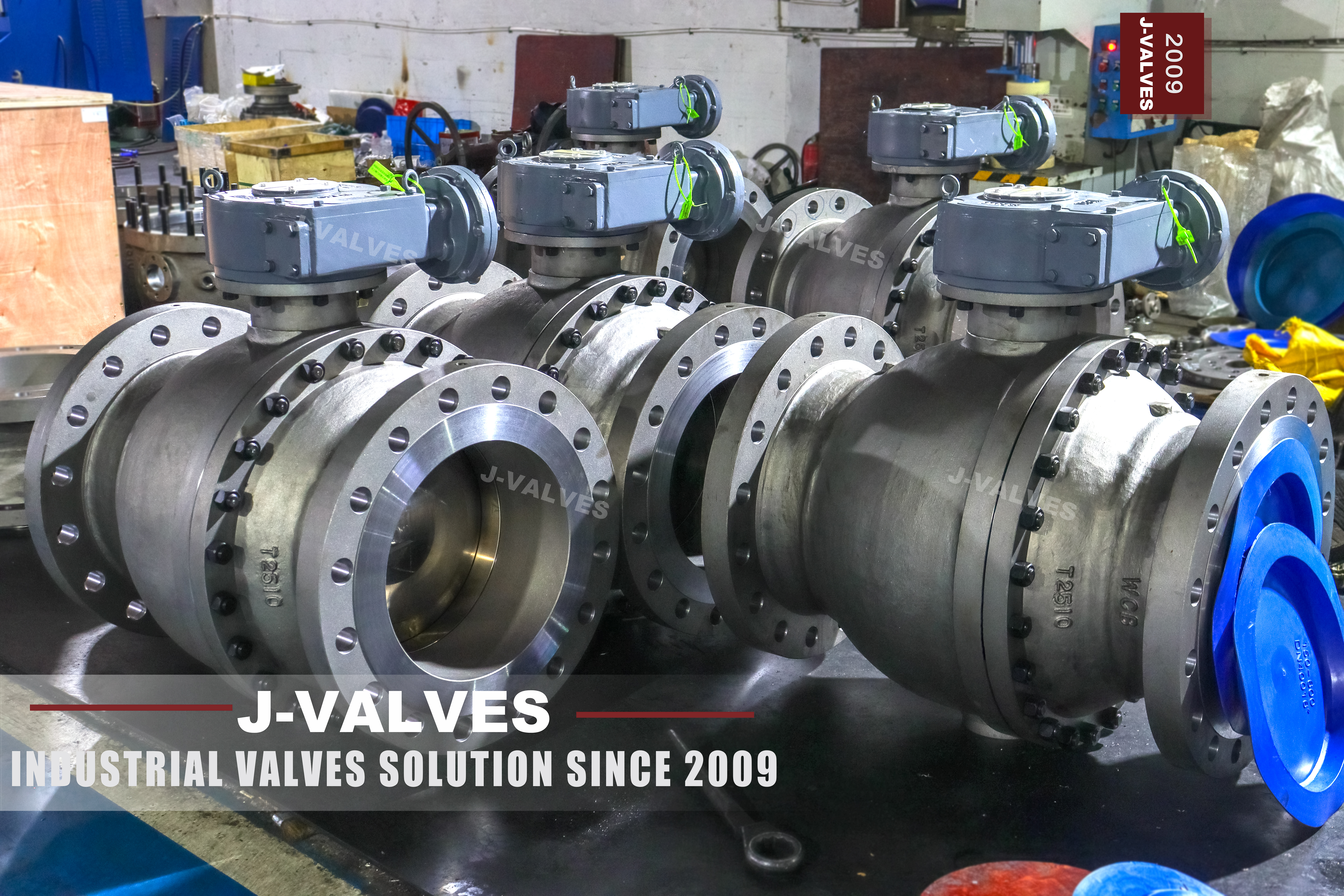
This is an NPS 8 valve in ASME Class 300, cast from ASTM A216 WCB carbon steel, built on a two piece side entry body with a full bore, raised face flanged ends drilled to ASME B16.5, and a bare stem on an ISO 5211 top flange. The ball is carried on an upper and a lower trunnion, so the thrust of the line pressure goes into bearings instead of into the seats, and the seats are spring energised pistons that give double block and bleed, with anti static bonding and a fire safe design to API 607.
The name on the page deserves a paragraph, because it is the reason this valve gets quoted wrong. "ANSI 8 PN50" is two numbers doing two different jobs. The 8 is a size, NPS 8 or DN200. The 300 is the pressure class, and 300 is what the casting is stamped. PN 50 is neither a second size nor a second class; it is the ISO name for Class 300. The nameplate on the body reads 8, 300 and WCB on three lines, and there is no fourth line saying PN 50, because PN 50 is a conversion and not a marking.
What follows from that is the most useful single fact on this page: there is no PN 50 flange in EN 1092-1. The European rating series steps from PN 40 to PN 63 with nothing in between, and PN 50 survives only as the approximate match for Class 300 in ISO 7005 and as the metric designation in the pressure class table of API 6D clause 7.2. A requisition that says PN 50 flanged is therefore asking for an ASME Class 300 flange wearing an ISO name, and that flange has to be drilled to B16.5: 381 mm outside diameter, 330.2 mm bolt circle, twelve holes of 25.4 mm for 7/8 inch studs. Section 5 sets that out with the comparison that matters, which is why a PN 40 flange is not a substitute even though both have twelve holes.
The rest of the design is what the size demands. On an NPS 8 floating ball valve the seat would have to hold the whole thrust of the line pressure over an area that grows with the square of the bore, and the torque needed to turn the ball against that seat would long since have passed the point where a lever is sensible. A trunnion takes the thrust out of the seat and puts it into bearings, which is why every 8 inch Class 300 ball valve in pipeline service is trunnion mounted, and why the operator on this build is a gear unit.
The valve is designed to ASME B16.34 for wall thickness and pressure temperature rating, with API 6D as the product standard, ASME B16.5 for the end flanges and ASME B16.10 for the length. The cold working pressure of a Class 300 WCB body is 51.1 bar at 38 degrees C, against 19.6 bar for Class 150 and 102.1 bar for Class 600. Where a line is designed above what Class 150 carries but does not justify Class 600, this is the class that gets specified.
Design and Construction
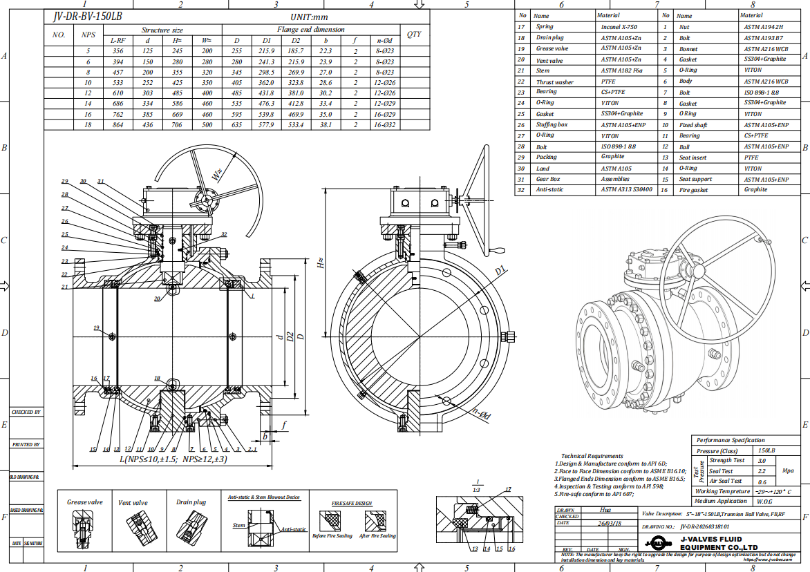
The body is split once. One end cap is bolted to the main body on a circle of studs with nuts, and the photograph shows that joint plainly: a full circle of studs standing proud of the joint face, nuts on the cap side, and a small socket screw on the joint line at mid height. Everything else lives in the single main casting — both seat pockets, the lower trunnion bearing, the stem neck, the ISO 5211 top flange, the cavity drain at the bottom and the sealant port on the side. Two piece, or 2PC in the trade, means exactly that: one pressure boundary joint instead of the two a three piece body carries.
That single joint is the whole argument for the pattern, and it cuts both ways. A two piece body has one gasketed joint under line pressure where a three piece body has two, one bolted circle to torque instead of two, and less metal to lift at NPS 8. The cost appears at maintenance: to reach the ball and the seats the end cap has to come off along the pipe axis, so the line has to give that space, either by breaking the far side of the joint or by taking out a spool. A three piece body leaves both end bodies on their pipe flanges and lifts the centre section out between them. The two piece body is the cheaper valve to buy and the more awkward one to work on, and that trade belongs in the purchase decision rather than in the catalogue.
Inside, the ball is held between an upper and a lower trunnion. The lower trunnion sits in a bearing at the bottom of the body, the upper one in the neck under the stem, and both run in metal backed, self lubricating bearings. The ball is inserted through the open end before the cap is closed, which is why the seat pockets can be machined as full circles in one body. The important consequence is that the trunnions, not the seats, take the side load the line pressure puts on the ball; the seats only have to seal, and the torque needed to turn the ball stays low enough for a gear unit at this size.
The stem is a separate part. It passes through the neck, is retained by the body so that it cannot be blown out, and does not touch the ball, so the side load on the ball never reaches it. The seal above it is a stack rather than a single ring: two O rings and a graphite gasket, which is the triple barrier arrangement, and the upper packing can be replaced with the valve in service once the cavity has been vented. A sealant injection fitting is standard on the stem.
The seats are pistons in their pockets, pushed against the ball by a ring of coil springs. The springs give the initial sealing force at atmospheric pressure; as the pressure rises it acts on the back of the seat and adds to that force in proportion. On the standard single piston effect seat, pressure trapped in the body cavity pushes the downstream seat away from the ball, so the cavity relieves itself into the low pressure side — which is what makes the standard build safe in liquid service, where a full cavity can be pushed open by thermal expansion. If double piston effect seats are ordered instead, both seats are pushed towards the ball by whatever is in the cavity, the valve seals both ways and holds a double barrier, and the cavity can no longer relieve itself: an external relief device becomes mandatory. That choice is a line item on the order, not a detail.
Double block and bleed follows from the same parts. With the valve closed and both seats sealing, the cavity is isolated from both sides; open the drain and what comes out — or does not — tells you whether both seats hold. Because the drain sits at the lowest point of the body it also empties the cavity before the joint is broken, and anti static bonding runs a conductive path from ball to stem to body.
Material Options
WCB is the right body material for this size and this duty, and it is also the reason the temperature range on the data sheet needs reading twice. ASTM A216 WCB is a cast carbon steel in group 1.1 of ASME B16.34, good from minus 29 degrees C to 425 degrees C, and it is cast rather than forged because a DN200 body is large enough that casting is the economical route. Above 425 degrees C the answer is a chromium molybdenum casting rather than a thicker wall.
The ball is the wear part. The standard build is a carbon steel ball, A105N or WCB, with hard chromium plating, which suits water, oil and gas and gives a hard surface against the seat; a 304 or 316 stainless ball is the option for corrosive media or where the customer's specification forbids a plated carbon ball. The ball grade that ships is written on the EN 10204 3.1 certificate, and the plating thickness belongs on the drawing, because that is the number that decides how long the ball lasts.
The stem is 17-4 PH by default, with 316 stainless as the option: a strength and corrosion trade, since 17-4 PH gives a harder stem in a smaller section and 316 is safer in chloride bearing service. Neither choice changes the pressure class.
The seat compound is where the valve's real temperature limit is set. RPTFE is standard, PPL and nylon are the higher temperature and higher abrasion options, and a metal seat with a cobalt alloy overlay is the option for the top of the temperature range and for abrasive service. The seat is the softest thing in the pressure boundary: a valve with a thermoplastic seat cannot be sold against the 425 degrees C that the WCB body allows, and a data sheet that prints minus 29 to plus 425 as one range is quoting the shell and not the valve. Shell and seat are two lines, not one.
The bearings are 440C stainless with self lubricating bushes, with a nickel alloy, UNS N06625, as the upgrade. Stem packing is flexible graphite, with a low emission arrangement to ISO 15848 on request. No trademarked alloy name appears in this specification: a brand name reads as a commitment to one supplier, and the standard designation is what a purchaser can check on a certificate.
| Component | Standard Material | Optional Upgrade | Service Notes |
|---|---|---|---|
| Body and end cap | ASTM A216 WCB cast carbon steel | A352 LCB for low temperature, A351 CF8M for corrosive media | Group 1.1 of ASME B16.34, minus 29 to 425 degrees C, cast in one main body plus one end cap |
| Ball | A105N or WCB, hard chromium plated | 304 or 316 stainless steel | Ball is the wear part; plating thickness stated on the drawing, grade on the 3.1 certificate |
| Stem | 17-4 PH precipitation hardening stainless | 316 stainless steel | Independent of the ball, anti blowout, replaceable packing with the valve in service |
| Seat | RPTFE | PPL, nylon, metal seat with cobalt alloy overlay | The seat compound sets the temperature limit, not the body material |
| Trunnion bearings | 440C stainless, self lubricating | Nickel alloy, UNS N06625 | Carries the side load of the line pressure, keeps operating torque low |
| Stem packing | Flexible graphite | Low emission arrangement to ISO 15848 | Triple barrier with two O rings and a graphite gasket, repackable in service |
| Body joint gasket | Gasket and O ring at the single body joint | Graphite for fire safe duty | One pressure boundary joint on a two piece body, both faces machined as a pair |
| Body joint bolting | Alloy steel studs and nuts | — | Grade declared on the 3.1 certificate, torqued in a cross pattern |
| Anti static device | Spring loaded contact between ball, stem and body | — | Continuity checked on every valve, not sampled |
| Surface finish | Grey primer as photographed | RAL 5015 sky blue on request | Machined flange faces and bore left bare, paint is not a specification of this valve |
Technical Specifications
The row that decides whether this valve fits the line is the flange drilling, not the pressure class. NPS 8 in Class 300 is 381 mm outside diameter on a 330.2 mm bolt circle with twelve holes of 25.4 mm, and the end flange in the front view of the product photograph shows those twelve holes and that proportion of face width. A valve drilled to any other pattern is a different valve, whatever the nameplate says, and the only check that settles it on site is the bolt circle and the hole diameter measured with a tape and a caliper.
The bore is full, taken from table 1 of API 6D rather than from the inside diameter of the pipe. The photograph is useful here because the ratio can be read off it: the bore in the front view measures a little over half the flange outside diameter, which is the full bore proportion for NPS 8, while an 8 x 6 reduced bore build would read about four tenths. That matters because the reduced bore version of this valve exists as a separate product, at the same size and class, and the two are not interchangeable on a line that is pigged: a reduced bore valve is the narrowest point in the run and the pig has to be sized on it.
Face to face is fixed by ASME B16.10, which gives one length for a Class 300 flanged valve at NPS 8. That is one of the advantages of an ASME rated valve over a PN rated one: the European length standard arranges valves by series, so two valves of the same size and rating can differ in length, while B16.10 gives a single number per size and class. It is still stated on the general arrangement drawing, because that is the document a purchaser can hold a supplier to if the valve does not fit the gap on site.
| Item | Value |
|---|---|
| Product type | Two piece side entry trunnion mounted ball valve, full bore, flanged |
| Nominal size | NPS 8, DN200 |
| Pressure class | ASME Class 300, recorded as PN 50 in API 6D clause 7.2 |
| Cold working pressure | 51.1 bar at 38 degrees C, ASME B16.34 group 1.1, WCB |
| Body material | ASTM A216 WCB cast carbon steel |
| End connection | Flanged, raised face as standard, ring type joint on request |
| Flange standard | ASME B16.5, Class 300 |
| Flange drilling | NPS 8 Class 300: 381 mm outside diameter, 330.2 mm bolt circle, 12 holes of 25.4 mm for 7/8 inch studs |
| Face to face | ASME B16.10, Class 300 NPS 8, value on the general arrangement drawing |
| Bore | Full bore to API 6D table 1; reduced bore 8 x 6 is a separate product |
| Body cavity | Self relieving with single piston effect seats, drained at the lowest point |
| Double block and bleed | Standard, cavity drain between the two seats |
| Anti static | Conductive path across ball, stem and body |
| Fire safe | API 607, method identical to ISO 10497 |
| Operation | Bare stem with key on an ISO 5211 top flange; gear unit, pneumatic or electric by order |
| Design standard | ASME B16.34 wall thickness and rating, API 6D product standard |
| Test standard | API 598, shell at 1.5 times and seat at 1.1 times the rating at 38 degrees C |
| Temperature | Body minus 29 to 425 degrees C; the seat compound sets the working limit |
| Support | No body feet on this pattern; the weight passes through the end flanges to the pipe |
| Torque and weight | Measured on the built valve, issued with the signed drawing |
Standards and Compliance
Four documents do the work, and each answers a different question. ASME B16.34 gives the wall thickness and the pressure temperature table, which is where 51.1 bar at 38 degrees C comes from. API 6D is the product standard: it requires double block and bleed, defines the cavity relief requirement, sets the fire safe and anti static requirements and calls up the test regime. ASME B16.5 fixes the end flanges and the drilling, ASME B16.10 fixes the length. The test is API 598, shell at 1.5 times the rating and seat at 1.1 times, and API 607 is the fire test, which is a type test on a representative valve rather than a test on every unit.
The traps on this page all come from the same place — a data sheet written by converting rather than by citing. The first is the equation Class 300 equals PN 50. It is correct, because API 6D clause 7.2 lists seven metric designations opposite the seven ASME classes with Class 300 reading PN 50, and ISO 7005 gives the same approximate match. What is not correct is any assumption that a PN 50 flange therefore exists as a European flange. EN 1092-1 has no PN 50 at all, so a PN 50 order is an ASME order, drilled to B16.5.
The second trap is the assumption that PN 40 will do instead, because it is close and both flanges have twelve holes. It will not. A PN 40 DN200 flange is 375 mm outside diameter on a 320 mm bolt circle with twelve holes of 30 mm; a Class 300 NPS 8 flange is 381 mm on 330.2 mm with twelve holes of 25.4 mm. The outside diameters differ by 6 mm and the bolt circles by 10.2 mm, which a tape will not settle in a dim light, and both flanges have twelve holes, so counting holes settles nothing either. What settles it is the hole: 30 mm against 25.4 mm. The M27 stud that suits the PN 40 holes does not pass through a 25.4 mm hole, and a 7/8 inch stud in a 30 mm hole leaves the joint to be centred by eye. This is a harder version of a familiar error, because counting bolts — the usual field check — gives the same answer for both flanges.
The third trap is ASME B16.47. The body text on the original page offers B16.5 or B16.47 for the end flanges, and at NPS 8 that second option does not exist: B16.47 begins at NPS 26. The same paragraph uses the word ANSI, which is trade shorthand rather than a current standard number, harmless on a factory drawing but not in a requisition, where the standard and the class have to be named.
Two further documents belong on the order rather than in the catalogue. NACE MR0175, with its identical twin ISO 15156, governs material for sour service and is the current designation for what older data sheets still call MR-01-75; if the line carries wet H2S the trim has to be ordered to it. ISO 15848 governs fugitive emissions, and a low emission stem arrangement is a tested design rather than a packing choice, so it is either ordered or it is not claimed.
| Requirement | Standard | What J-VALVES Supplies |
|---|---|---|
| Wall thickness and pressure temperature rating | ASME B16.34, group 1.1 | Body wall calculated and cast to the standard, 51.1 bar at 38 degrees C for Class 300 |
| Product requirements for pipeline valves | API 6D | Double block and bleed, cavity relief, anti static, fire safe, marking and test regime |
| End flanges and drilling | ASME B16.5, Class 300 | NPS 8: 381 mm outside diameter, 330.2 mm bolt circle, 12 holes of 25.4 mm |
| Face to face | ASME B16.10 | Single length per size and class, stated on the general arrangement drawing |
| Pressure test | API 598 | Shell at 1.5 times and seat at 1.1 times the rating at 38 degrees C, with a low pressure gas seat test to API 6D |
| Fire safe | API 607, identical to ISO 10497 | Type tested design, certificate issued with the valve |
| Fugitive emissions | ISO 15848 | Low emission stem arrangement on request, with the test report |
| Sour service | NACE MR0175 and ISO 15156 | Trim and bolting ordered to the standard when the line carries wet H2S |
| Material certificates | EN 10204 3.1 | Certificate per heat, matched to the marking on the body |
| Metric designation | API 6D clause 7.2 and ISO 7005 | Class 300 recorded as PN 50 on documents, flanges still drilled to ASME B16.5 |
Manufacturing Process
The body starts as a sand casting in WCB, from a pattern that puts both seat pockets, the trunnion bore and the neck in the same drag. Castings are cleaned, risers cut back and surfaces inspected before machining, and any weld repair is made to a qualified procedure and re examined afterwards, because an undocumented repair is the one thing a purchaser cannot see in a finished valve.
Machining is where a two piece body earns or loses its reputation. The joint faces of the body and the end cap are machined as a pair against the same reference, so the gasket groove and the stud circle line up when the halves meet; the seat pockets are bored from the joint face, which is possible only because the pocket is a full circle in a body that opens at one end; and the trunnion bore in the neck and the bearing seat at the bottom are machined on one axis, so the ball turns about a line square to the bore. The flange faces are finished to the roughness B16.5 calls for and the stud holes drilled on the bolt circle at 25.4 mm.
Assembly runs from the inside out. The ball is lapped, the seats and spring rings are fitted, the ball and trunnion assembly goes in through the open end, the end cap is closed on its gasket and the studs are torqued in a cross pattern to a figure recorded on the traveller. The stem is fitted from the top, with its thrust bearing, O rings and graphite packing, and the gland is set so that the stem can still be turned by hand before the gear unit or the bare stem cover goes on. Every valve is then turned through a full quarter, both directions, before it goes to test.
The paint line is the one place where the original page and its own photograph disagree. The text specifies sky blue RAL 5015; the photographs show a grey primed body with bare machined faces, and no blue anywhere. On a carbon steel valve a primer and a topcoat are both normal and neither is a technical claim, but a data sheet that promises a colour the photograph contradicts invites the question of what else was copied. The build photographed here is grey primer, and a topcoat colour is an order option.

Quality Control and Testing
Testing starts with the shell at 1.5 times the rating at 38 degrees C, with no leakage through the wall, the joint or the stem seal. The body joint is where this test earns its keep on a two piece valve: a joint that weeps under the shell test will weep in service, and it is the only pressure boundary the pattern adds.
The seat test follows at 1.1 times the rating, each seat with pressure on its own side, and API 6D adds a low pressure gas seat test on top, because a seat that holds water can still leak gas. Double block and bleed is then demonstrated rather than assumed: valve closed, cavity drain open, each side pressurised in turn, drain watched. A valve that passes the seat test but shows pressure at the drain has a problem the standard test would not have found.
The dimensional check decides whether the valve will bolt up, and it is done with a caliper and a bolt circle gauge: outside diameter, bolt circle, hole diameter, hole count, face to face and face squareness. On this size the hole diameter is the number that separates a B16.5 Class 300 flange from a PN 40 lookalike, so it is measured and recorded. Anti static continuity is checked on every valve, and the fire safe and low emission certificates are issued at design level, which is what those standards provide for.
Marking is checked last, because it is what the site reads. The body carries the size, the class, the material grade and a works number, and the nameplate carries the manufacturer, the class, the size and the material, with the heat number tying the valve to its 3.1 certificate. The works number on this casting appears as a short alphanumeric code and is sometimes mistaken for a material grade in photographs; it is not one, and no grade should be read from it.
| Step | What Is Checked | Standard or Acceptance |
|---|---|---|
| Shell test | Body, body joint and stem seal under pressure | API 598, 1.5 times the rating at 38 degrees C, no leakage |
| Seat test | Each seat with pressure on its own side | API 598, 1.1 times the rating, no leakage past the seat |
| Low pressure seat test | Seat tightness with gas after the hydrostatic test | API 6D, low pressure gas, no bubbles |
| Double block and bleed | Both seats closed, cavity drain open, each side pressurised in turn | No flow at the drain with either side under pressure |
| Dimensional check | Outside diameter, bolt circle, hole diameter, hole count, face to face | ASME B16.5 Class 300 NPS 8 drilling, ASME B16.10 length, recorded on the inspection sheet |
| Anti static | Continuity from ball to stem and stem to body | API 6D, measured on every valve with a milliohmmeter |
| Marking and traceability | Size, class, material and works number on the body; nameplate data | API 6D marking, heat number matched to the EN 10204 3.1 certificate |
| Certificate pack | Material, pressure test, fire safe, low emission where ordered | 3.1 certificate per heat, test record, type test certificates |

Applications and Industry Service
This valve belongs on the isolation points of a line that is designed above what Class 150 will carry but does not justify Class 600: gas transmission and distribution stations, meter and regulator runs, pump and compressor discharge, tank farm headers, and water transmission mains where the surge pressure rules out a lighter class.
It is as useful to say where this valve should not be used, because that is where most of the misfits in this class come from. It is not a cryogenic valve: WCB stops at minus 29 degrees C, and a low temperature line needs LCB or an austenitic body, which is a different product and not an option on this one. It is not a subsea valve and not a wellhead valve: the subsea and wellhead standards are different documents with different test regimes, and a page that lists those approvals against a flanged Class 300 valve is describing a catalogue rather than a product. It is not a high temperature valve above the WCB ceiling, where the answer is a chromium molybdenum body. It is not a sour service valve unless the trim is ordered to NACE MR0175. And it is an isolation valve, not a control valve: a ball valve used to throttle will wire draw its seat and lose the tight shutoff it was bought for.
For a European project the practical point is the one in section 5. A piping class sheet may well call this a PN 50 valve, and that is a legitimate way to name it, but the gasket and the studs have to come from the ASME B16.5 list for Class 300 NPS 8 and not from the PN 40 list, because the two flanges are not the same flange. Order the studs with the valve and they will be right; take them off the PN 40 schedule and the joint will not close.
Installation, Operation and Maintenance
Lifting is the first thing to get right at this size. The valve is a two piece casting with no lifting eyes on the photographed build, so the sling goes around the body with a spreader, or through the two end flanges with a bar and soft slings, and never around the stem, the top flange or a fitted gear unit. The top flange is an actuator mounting face; it is not a lifting point and it is not designed to carry the valve's weight.
Support comes second. There are no body feet on this pattern, so the weight of the valve passes through the two end flanges into the pipe, and the pipe either side has to carry it. Put independent supports close to both flanges and do not use the valve as a pipe support: a joint that is holding the valve's weight as well as the line's is a joint that will weep.
Bolting up is straightforward if the parts are right. The gasket goes in dry and centred, the faces are brought together parallel, and the twelve 7/8 inch studs are tightened in a cross pattern in two or three passes. Check the bolt circle and the hole diameter before the studs go in, not after: if the holes are 30 mm rather than 25.4 mm, the valve is a PN 40 pattern and no amount of torque will make the joint right.
Operation is a quarter turn, open or closed, with the gear unit or the actuator fitted to the ISO 5211 top flange. Set the stops so that the ball is exactly at the end of its travel in both positions, and do not leave the valve part open to control flow. If an actuator is fitted, its sizing comes from the breakaway torque measured on the built valve, not from a catalogue figure for the size, and the fail position has to be stated on the order.
Maintenance is mostly about what can be done live. The stem packing can be replaced with the valve in service, once the cavity is vented and the gland is backed off, because the stem is retained by the body and the packing sits above the pressure boundary. The seat sealant injection fitting is an emergency measure that buys time until the line can be taken out, and it is not a repair. Replacing the seats means isolating the line, draining the cavity through the plug at the lowest point, breaking the single body joint and opening the pipe enough to take the end cap off. Nothing on the body joint or in the seat pockets is accessible under pressure, and no welding should be done on a WCB body in service without a procedure and a post weld heat treatment decision.
How to Specify and Order
A purchase order for this valve needs eight lines, and the first two are the ones that go wrong. Size: NPS 8, DN200. Class: ASME Class 300, with a note if the project calls it PN 50, and a note of the facing, raised face or ring type joint — one or the other, not both. Then the bore, full or 8 x 6 reduced, because they are two different products. Then the body material, A216 WCB, and the trim: ball, stem and seat compound, each named rather than offered as a slash list. Then the operator: bare stem on an ISO 5211 pad, gear unit, pneumatic or electric, with the fail position if it is actuated. Then the tests and certificates: API 598 test record, EN 10204 3.1 material certificate, API 607 fire certificate, ISO 15848 report if the line is regulated for emissions, NACE MR0175 if the service is sour.
For a quotation, four more things are needed than the eight above. The medium, because it decides the trim. The design pressure and the design temperature together, because the rating is a curve and not a number. The differential across the valve, because it is what the actuator has to overcome. And whether the line is pigged, because it decides whether the reduced bore version can be offered at all.
What ships with the valve is part of the specification rather than an afterthought: the signed general arrangement drawing with the face to face dimension, the pressure test record, the 3.1 material certificate matched to the marking on the body, the fire safe certificate, and the installation and maintenance instructions. Torque, weight and flow coefficient are measured on the built valve and appear on that drawing, not in a catalogue table, because each of them moves with the trim and the differential.
The last line of the order should name the flange standard twice — once as the class and once as the drilling. Class 300 does not describe a bolt pattern on its own, and PN 50 describes it less: it is a name for the class, not a flange in any European table. Write ASME B16.5 Class 300, NPS 8, twelve holes of 25.4 mm on a 330.2 mm bolt circle, and the joint will close the first time.
FAQ
Q: Is PN 50 the same as Class 300?
A: As a designation, yes; as a flange, no. API 6D clause 7.2 pairs Class 300 with PN 50 in its table of metric designations, and ISO 7005 gives the same approximate match, so a data sheet that calls this a PN 50 valve is not wrong. What does not exist is a PN 50 flange. EN 1092-1 runs 25, 40, 63 and upwards with nothing at 50, so a PN 50 order is an ASME Class 300 order and has to be drilled to B16.5: 381 mm outside diameter, 330.2 mm bolt circle, twelve holes of 25.4 mm for 7/8 inch studs.
Q: Can a PN 40 flange be used instead, since both have twelve holes?
A: No, and this is the trap that costs a shutdown. A PN 40 DN200 flange is 375 mm outside diameter on a 320 mm bolt circle with twelve holes of 30 mm. The Class 300 NPS 8 flange is 381 mm on 330.2 mm with twelve holes of 25.4 mm. Both are twelve hole flanges, so counting bolts settles nothing; the outside diameters are 6 mm apart and the bolt circles 10.2 mm apart, which is inside what a tape will argue about. The hole is what separates them: an M27 stud for the PN 40 pattern does not pass through a 25.4 mm hole.
Q: Why is the body two piece at this size, and what does that cost in maintenance?
A: It costs one pressure boundary joint instead of two, and less metal to lift. A two piece body has one bolted, gasketed joint under line pressure where a three piece body has two, which is one less leak path and one less circle of studs to torque. The cost comes at maintenance: to reach the ball and the seats the end cap has to come off along the pipe axis, so the line has to give that space, either by breaking the far side of the joint or by lifting out a spool. The 8 x 6 reduced bore and the top entry patterns solve the same problem differently, and the choice is a station layout question rather than a valve question.
Q: Is the bore full, and can the line be pigged?
A: The bore is full to table 1 of API 6D, and the front view of the product photograph confirms it: the bore measures a little over half the flange outside diameter, which is the full bore proportion for NPS 8, where an 8 x 6 reduced bore build would read about four tenths. That matters for pigging because the valve is the narrowest point in the run, so the pig is sized on the valve bore. If the line is pigged with a gauge plate, the reduced bore version of this valve cannot be used at all, whatever the pressure class says.
Q: Can an actuator be fitted, and why are there no torque figures?
A: An actuator can be fitted to the ISO 5211 top flange, and the photographed build shows that face with four studs and a bare keyed stem and no operator, which is how the valve leaves the works unless an operator is ordered. Torque is not printed on this page because it is not a property of the size: it follows the seat compound, the differential, the temperature and the safety factor in the purchaser's own specification, and a catalogue number would be a guess dressed as a specification. It is measured on the built valve and issued with the signed drawing, together with the fail position the order asks for.
Q: What is the real temperature limit of this valve?
A: Two limits, and the lower one governs. The WCB body is good from minus 29 to 425 degrees C, which is the group 1.1 range of ASME B16.34, and above that the answer is a chromium molybdenum casting rather than a thicker wall. The seat is the lower limit: a thermoplastic seat such as RPTFE cannot be sold against 425 degrees C, and only the metal seated option with a cobalt alloy overlay reaches the top of the body range. So the shell range and the seat range are two lines on a data sheet, and the valve is limited by the second.


Hot Products


News
Ball Valves in Geothermal Brine: Silica Scale, Chloride Cracking And The Cooling Trap
Why geothermal brine destroys ball valves: retrograde silica scale, calcite at the flash point, chloride cracking above 60 C and the 250 C seat limit.
Read More
Ball Valve Face To Face Dimensions: Why A Correctly Ordered Replacement Still Does Not Fit
A 6 inch Class 150 ball valve can be 267 or 305 mm face to face and both are compliant. How B16.10, EN 558 and flange drilling decide whether it fits.
Read More
Ball Valve Stem Key And Keyway: What Gives Way First, And What The Handle Cannot Tell You
Between the handle and the ball there are four fits. Which one shears, which one cracks, and how a few degrees of lost motion hides a valve that never seated.
Read More
Ball Valve Datasheet: Six Blocks That Decide Whether Two Quotes Are Comparable
A ball valve datasheet only works when six blocks are fixed: pressure basis, bore, temperature ceiling, test, end connection, operator. How each is written.
Read More