


CHINA J-VALVES Offers Various High-quality I ndustrial Ball Valves
J-VALVES, a distinguished professional ball valve manufacturer rooted in China, takes pride in its extensive product portfolio. Our offerings span a wide range, including trunnion-mounted ball valves, floating ball valves, high-temperature ball valves, high-pressure ball valves, metal-sealed ball valves, ultra-low temperature ball valves, DBB ball valves, Three-way And Four-way Ball Valve, and fully welded ball valves. Each product is a testament to our commitment to precision engineering and reliable performance. Meticulously crafted, they are designed to not only meet but exceed the most stringent industrial demands, ensuring stable operation even under extreme conditions. This enables us to provide our clients with high-value services and makes our valves widely sought-after in industries.
Product Category
Contact Us


-
J-VALVES-Q347F
-
J-VALVES
Overview of the J-VALVES 16 Inch Class 300 Gear Operated Trunnion Ball Valve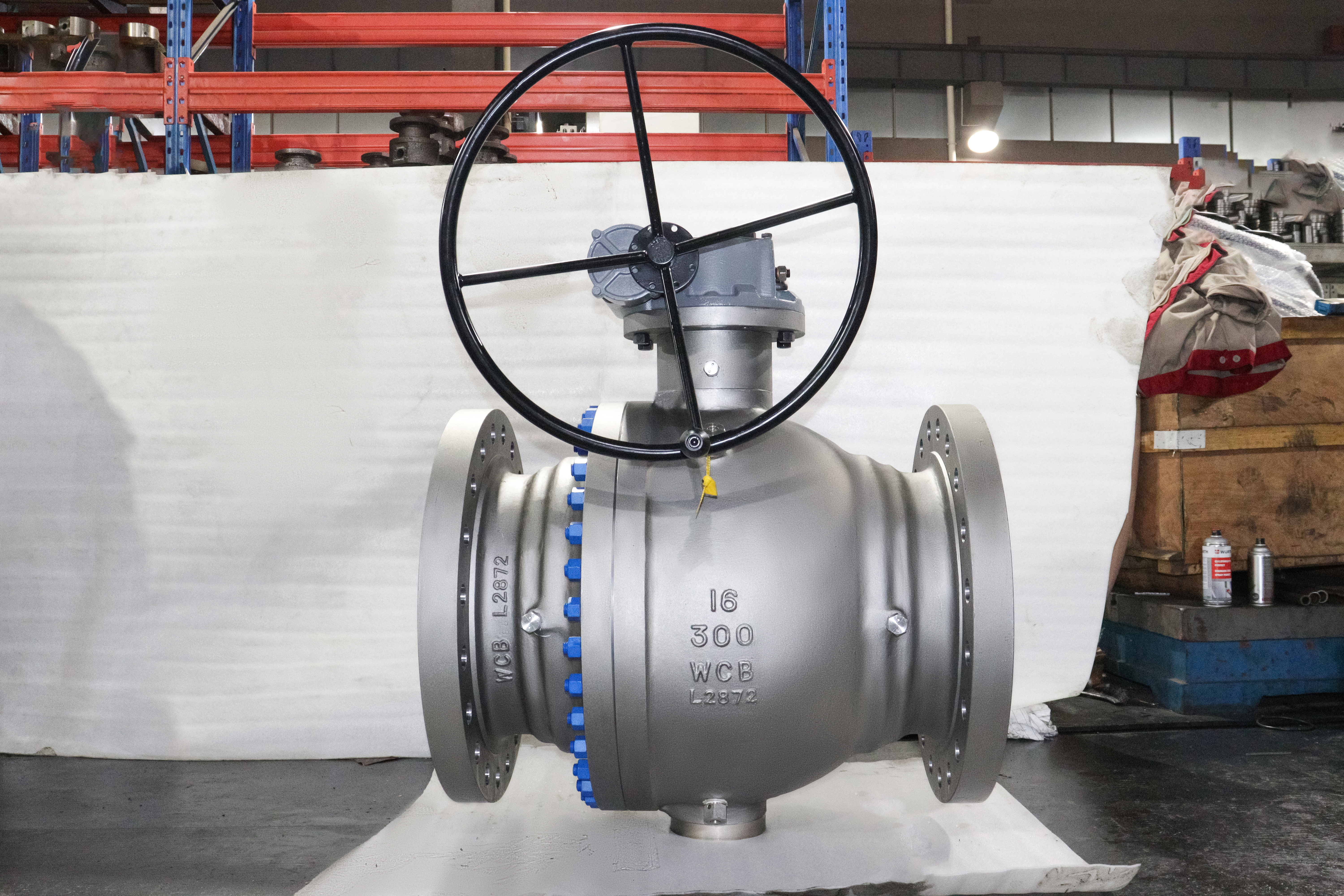
The J-VALVES 16 inch Class 300 gear operated trunnion ball valve is a large bore isolation valve for ASME pipework. A DN400 full bore, an A216 WCB body split into a main body and one bolted end cap, a ball carried on an upper and a lower trunnion instead of resting on its seats, soft seats with single piston effect as standard, raised face flanges to ASME B16.5 for NPS 16 Class 300, and a right-angle gearbox with a spoked handwheel on its input shaft. The body casting carries four marks: 16, 300, WCB and the heat number.
This page is written around the part of the valve that a buyer cannot see. At DN400 the operator is the one place where a person meets a large steel assembly held at pressure, and the figures that decide whether the valve still turns in five years are not in ASME B16.34, are not fixed by API 6D unless the purchaser asks, and are not visible on any photograph. The ten sections below therefore follow four items that belong in the order rather than on the drawing: how much effort the handwheel takes, which gear is inside the box, how the body joint is bolted, and what an actuator would need to fit later.
The duty this valve is built for is infrequent, local, manual isolation: transmission laterals, meter and regulating stations, compressor station headers, pig trap isolation, tank farm manifolds and large bore utility water. Where the valve has to cycle every day, or close on command from a control room, the same body is ordered with an actuator, and the gearbox is replaced rather than stacked underneath one. Both versions share the body, the ball, the stem and the joint. Only the top works changes, which is why the top works has to be decided early.
Design and Construction
The handwheel does not turn the ball directly, and the length of the chain is why a large valve feels different from a small one. Effort passes from the handwheel through the input shaft, the gear pair, the output sleeve, the stem and the ball to the trunnion journals. Four frictions sit in that chain: the seat ring dragging on the ball, the trunnion journal in its bearing, the packing gripping the stem, and the gear pair itself. The handwheel feels the sum divided by the ratio and multiplied by the losses of the box, which is why the ratio alone does not predict how hard the valve is to turn.
Two torques matter and they are not the same number. Breakaway is what the operator needs to move a ball that has been sitting closed against a loaded seat, and it carries stiction, the compression set of the seat, and in dirty service a film of deposit on the seat band. Running torque, once the ball is free, is lower. A gearbox sized on running torque will pass the factory test and stall in the plant after a year of sitting closed, which is why API 6D's design validation asks for the breakaway and running figures to be measured at the maximum design pressure difference rather than at a convenient one.
The photograph shows a right-angle gearbox: input shaft horizontal, output vertical, spoked handwheel on the input. What it does not show is whether the pair inside is a worm or a bevel, and that is not a detail. A worm pair with a lead angle below its friction angle is self-locking, so the ball stays where the operator left it; a bevel pair is not, and on a part open ball the flow can push the ball towards open or towards closed. For isolation at the two end positions the difference hardly shows. For a valve that may be left part open, or that sits on a line with reversing flow, it decides whether the ball drifts. Ask which pair is fitted, in writing.
The stem passes through the body cover and is retained by it, so it cannot be blown out, and the gearbox sits outside the pressure boundary. Removing the operator leaves the stem in place and the valve sealed: the top works is not a pressure part and its bolts hold no pressure. That is what makes one maintenance action possible with the line live: with the valve closed and the cavity vented, the gearbox can come off and the stem packing and the upper stem rings can be renewed. Nothing else on this valve can be worked on without isolating it, because everything else is on the boundary.
Travel is limited inside the gearbox. The stops are set at assembly against the ball position and locked, and they are not a comfortable place to be generous: over-travel drags the edge of the port across the seat band, and under-travel leaves the port misaligned so that the seat is only partly loaded and the bore is narrowed. Both conditions survive a hydro test and show up as erosion or as a leak later. After any change of operator, including an actuator retrofit, the stops are re-set against the ball, not against the old gearbox.
The body joint is one ring of studs and one gasket, and it is the one item in this valve that no standard covers. ASME B16.5 describes the pipe flange, ASME B16.34 fixes the shell wall, API 6D requires the joint to be as strong as the shell and to be verified, and none of them prints a stud count, a stud grade or a joint face thickness. Two DN400 Class 300 valves from two makers can therefore have entirely different joint bolting and both pass the same shell test. Ask for the joint bolting on the drawing, and keep a spare set of joint studs: they are not the pipe flange studs, and the pipe studs will not fit.
End cap access is a drawing item too. The cap has to come off along the axis to release the ball and both seats, and at this size that is a lifting job with a sling and a clear space behind the flange, so the general arrangement drawing has to show the withdrawal clearance. On a line where the downstream flange sits close to a bend, a support or a wall, that clearance is discovered at the first seat change rather than in the drawing office.
The body in the photograph also carries a screwed fitting that leads into the seat pocket and a plug at the lowest point of the cavity, and each is a drilled path through the pressure boundary. The fitting is an emergency device: it buys time on a seat that has started to pass, it pushes debris deeper into the band if solids caused the leak, and a seat that has been injected is a seat to be replaced at the first opportunity. The drain belongs at the lowest point because the cavity at this size holds a real volume of liquid, and that liquid has to be able to leave.
Material Options
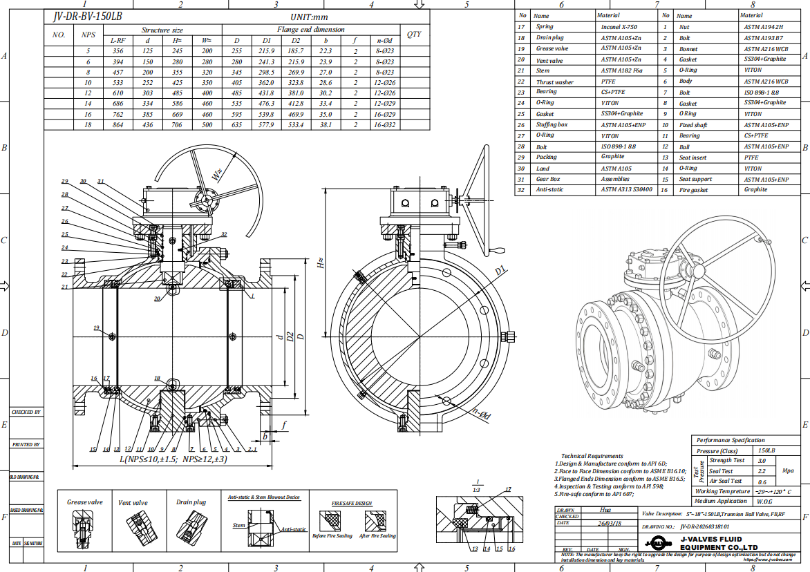
A216 WCB is the correct casting for a Class 300 carbon steel valve, and the photograph and the drawing agree on it: the body is cast and the casting is stamped WCB. In ASME B16.34 it sits in Group 1.1, which is the group whose ratings are the tabulated carbon steel values, so a heavier wall does not buy a higher class. A105 forged material is offered alongside and falls in the same group with identical ratings, so forging buys soundness and a thinner wall rather than a rating. The range moves to A350 LF2 below the carbon floor and to A217 WC6 or WC9 above the carbon ceiling.
The seat is what limits this valve, not the body. PTFE and RPTFE cover the ordinary range, PPL goes higher, and a metal seat with flexible graphite is a different product with a different leakage class. The minus 29 to plus 425 C printed in the sales table is the carbon steel ceiling from the rating table, and the seat will stop the valve well before the body reaches it; the governing limit is the lower of the two, which is why the seat is quoted against the medium rather than listed as a standard.
Two names in the original data sheet are trade names and not grades, and both need care on an order. Stellite is a trade name for a cobalt-chromium hardfacing, so a purchase order that asks for it will get whatever consumable the welder has, and the certificate will agree with the welder rather than with the drawing; write the alloy class or the welding procedure instead. The same discipline applies to the bearing material, which is best ordered by its UNS number. This is not pedantry: on a valve that may be inspected by a third party, a certificate that answers a brand name is a certificate that cannot be checked.
The ball is carbon steel with a hard chrome or electroless nickel coating, or a stainless ball as an alternative, and the coating is chosen against the medium rather than against the class. The joint gasket is a spiral wound with a graphite filler and a stainless inner ring, and the inner ring is a wetted part: on a carbon steel body in a corrosive medium it is the first component to look at, and it is renewed at every opening rather than reused. Bolting follows the service: B7 with 2H nuts as standard, and B7M with 2HM nuts where the line is sour.
| Component | Standard Material | Optional Upgrade | Service Notes |
|---|---|---|---|
| Body and end cap | ASTM A216 WCB, cast, stamped 16 / 300 / WCB / heat | A105 forged, or A350 LF2 for low temperature | Same B16.34 Group 1.1 as A105; forging is not a higher class |
| Ball | Carbon steel with hard chrome or ENP | F304 or F316 ball | The coating is chosen for the medium; the base metal stays carbon steel |
| Trunnion and bearings | 440C bearings in the bearing blocks | Nickel alloy bearings to a UNS number | Both blocks bored as a pair in the main body |
| Stem | 17-4PH | 316 stainless | Anti-blowout, retained by the body cover; hardness limit applies in sour service |
| Seat rings | PTFE or RPTFE in a metal carrier | PPL, or metal with flexible graphite | The seat sets the temperature, not the body |
| Body joint gasket | Spiral wound, graphite filler, stainless inner ring | — | Wetted part, renewed at every opening |
| Packing | Flexible graphite | PTFE V-rings | Graphite is the fire safe path |
| Joint bolting | A193 B7 with A194 2H | B7M with 2HM for sour service | A drawing item, not the pipe flange studs |
| Seat injection fitting | Needle valve with check, screwed into the body | — | Emergency measure, not a repair method |
| Top works | Machined pad, right-angle gearbox, spoked handwheel | Pneumatic or electric actuator | Pad size, drive form and stem height on the GA drawing |
Technical Specifications
Every figure in this table is either a value printed in a standard or a dimension that is confirmed on the signed drawing, and the table separates the two. The flange figures are the ASME B16.5 values for NPS 16 Class 300 and can be checked against the standard without asking anyone. Face to face is the ASME B16.10 value for this size and class, and is confirmed on the general arrangement drawing because the drawing also fixes the orientation of the gearbox. The bore is the API 6D table 1 minimum for a full bore valve at this size, which is the definition of full bore: a minimum, not a measurement.
| Item | Value |
|---|---|
| Nominal size | 16 inch, DN400 |
| Pressure class | 300, recorded as PN50 in API 6D clause 7.2 |
| Body material | ASTM A216 WCB, cast marks 16 / 300 / WCB / heat number |
| Body style | Two-piece, main body plus one bolted end cap |
| End connection | Flanged raised face, ASME B16.5, NPS 16 Class 300 |
| Flange outside diameter | 647.7 mm |
| Bolt circle | 571.5 mm, twenty holes for 1-1/4 inch studs |
| Raised face diameter | 469.9 mm |
| Bore | Full bore, the API 6D table 1 minimum for NPS 16 |
| Ball support | Upper and lower trunnion, both bearing blocks in the main body |
| Seat design | Soft seat, single piston effect as standard |
| Body joint | Bolted and gasketed ring, stud count and grade on the GA drawing |
| Stem | 17-4PH, anti-blowout, retained by the body cover |
| Operator | Right-angle gearbox with a spoked handwheel on the input shaft |
| Top works | Machined pad, size and drive form on the GA drawing |
| Shell temperature | Minus 29 to plus 425 C, B16.34 Group 1.1 |
| Seat temperature | Set by the seat material, below the shell limit |
| Face to face | ASME B16.10 value for NPS 16 Class 300, confirmed on the signed GA drawing |
| Design standard | ASME B16.34 and API 6D |
| Test standard | API 6D, shell at 1.5 times and seat at 1.1 times |
| Fire test | API 607, technically equivalent to ISO 10497 |
| Painting | System and colour agreed at order; flange faces, joint faces and bore masked |
Standards and Compliance
Class 300 in Group 1.1 is rated 740 psi at 100 F, the 51.1 bar entry at 38 C in the metric table of ASME B16.34, and the rating falls as the temperature rises. The class number is a label and the rating is what is read at the design temperature, which is why the same casting carries a much lower allowance on a hot line than on a cold one. Nothing in the standard makes a valve usable at its class number regardless of temperature.
What API 6D does not print is the whole subject of this page, and the reason is a structure inside the standard itself. The operating data lives in Annex L, which is normative but applies only when the purchaser specifies it at the time of order: the maximum pressure differential, the break to open and break to close torques, the run torques, the end to open and end to close figures, the breakaway angle, the maximum stem torque the drive train will take, the number of turns for a manually operated valve, and the top works dimensions. A valve can be fully API 6D and arrive with none of that paper, and the buyer has no way of knowing afterwards what the valve needed to turn it.
There is a quiet default in the same annex that is worth knowing before a line is written. The purchaser states the maximum pressure differential at which the valve must open; if the differential is left blank, the standard falls back to the pressure determined from the material at 100 F, which is the full cold rating of the valve. So a line that never runs near its class still gets an operator sized against the hardest case it will ever see, unless somebody writes the real differential into the order. That is cheap to fix at enquiry and expensive to discover when a handwheel cannot be turned.
Two further requirements in the same annex are purchaser-specified and are easy to miss. A drive train strength test, when ordered, applies twice the breakaway torque with the ball blocked for at least a minute, and the twist of the drive train must stay inside the overlap between seat and ball. And a single piece stem, when ordered, excludes welded fabrication and threaded stem assemblies. Neither is automatic. Both are the kind of clause that separates two valves that are compliant on paper from two valves that are the same product.
The interface above the stem has its own standard and its own gap. ISO 5211 fixes the mounting pad: bolt circle, thread, hole pattern, drive form, drive dimension and the torque the pad can carry. It does not fix the stem height above the pad face, the engagement length, or the clearance down to the gland, so two valves can quote the same pad size and still need different couplings for the same actuator. Quote the pad code and the drive size together, and take the stem height off the drawing rather than from a catalogue. A larger actuator does not enlarge the pad either: the pad rating is a ceiling that belongs to the valve.
The rest of the compliance list is short. API 6D is the product standard here and API 608 is a separate document with a different seat test regime, so only one of them belongs on the data sheet. API 598 fixes the test pressures, not the acceptance criterion. Fire safe is a test result, so API 607 and ISO 10497 are test rows rather than design standards, and the older API 6FA has been folded into 607. NACE MR0175 is the current designation for sour service, and the stem hardness is where a 17-4PH part is most likely to fail it.
| Requirement | Standard | What J-VALVES Supplies |
|---|---|---|
| Pressure and temperature rating | ASME B16.34 Group 1.1 | 740 psi at 100 F, 51.1 bar at 38 C for Class 300 |
| Valve design and manufacture | API 6D | Trunnion design, single piston effect seats, cavity drain |
| Flange drilling | ASME B16.5 | NPS 16 Class 300, twenty studs, raised face |
| Face to face | ASME B16.10 | Table value for the size and class, confirmed on the GA drawing |
| Body joint | No product standard | Strength proven against the shell, dimensions on the drawing |
| Shell test | API 6D | 1.5 times the rated pressure, every valve |
| Seat test | API 6D | 1.1 times, by cavity pressurisation, proving both seats |
| Fire test | API 607 and ISO 10497 | Certificate per order |
| Anti-static | API 6D | Spring plunger, resistance measured and recorded |
| Operating data | API 6D Annex L | Torque, turn count and top works dimensions when the order asks |
| Drive train strength | API 6D Annex L, when specified | Test at twice breakaway torque with the ball blocked |
| Marking | API 6D | Nameplate with size, class, material, heat number and serial |
| Actuator interface | ISO 5211 | Pad, drive form, drive size and stem height stated on the drawing |
Manufacturing Process
Body and end cap are cast from the same heat whenever the order allows, and the reason is the joint rather than the metallurgy. Two halves with different chemistries and different section sizes respond differently to machining and expand differently when the line heats up, and the joint face is where a difference of that kind shows first. One heat removes the variable, and the two heat numbers are recorded together on the certificate so the pair can be traced.
The joint faces are machined with the halves bolted together under a controlled load, and the stud holes are drilled in line with the faces in that condition. Machining each half separately produces two flat faces that do not match once the gasket is between them. This is the operation that decides whether the valve still seals after it has been opened once in the field, and it cannot be recovered by tightening the studs harder.
The trunnion bores are line bored with the bearing blocks in place, which is why the pair is treated as a single part and why the alignment reference never crosses the joint. The ball is machined, ground and coated after grinding, checked for roundness before it goes near a seat, and the whole assembly is turned dry with the operator fitted so that the stop positions and the gearbox setting are proved together.
The top pad is machined in the same setup as the stem bore. The gearbox output has to be coaxial with the stem, and the only reliable way to achieve it is to cut both from the same reference rather than to align them afterwards with shims. The operator is then mounted, the stops are set and locked, the assembly is cycled, and the painting is done last with the flange faces, the joint faces, the bore and the pad masked so that no paint film ends up under a gasket or across a sealing face.

Quality Control and Testing
Eight checks stand between the casting and the crate, and the first three cannot be recovered later: material certification with heat traceability, casting soundness, and the machined geometry of the flanges, the joint faces and the bore. The next three are assembly: bearing fit, seat squeeze and gland load. The last two are the pressure tests and the marks. The operating torque check sits between them, and unlike the others it exists only if the order asks for it.
| Step | What Is Checked | Standard or Acceptance |
|---|---|---|
| 1 Incoming material | Chemistry and mechanical properties, heat number | Certificate traceable to the casting |
| 2 Casting integrity | Visual and ultrasonic at joint faces and seat pockets | No linear indications |
| 3 Machining | Flange facing, joint face flatness, bore roundness | Drawing, B16.5 for the flange |
| 4 Bearing fit | Trunnion bores and block alignment | Blocks bored as a pair in the main body |
| 5 Assembly | Seat squeeze, gland load, stop setting | Assembly sheet, stops locked |
| 6 Anti-static | Resistance from ball to body through the stem | Measured and recorded |
| 7 Pressure test | Shell at 1.5 times, seat at 1.1 times by cavity | API 6D, with the operator fitted |
| 8 Operating torque | Breakaway and running at the test pressure | Recorded when the order asks, per API 6D Annex L |
| 9 Final | Marking, joint stud set, painting, documents | Serial matched across all documents |
Three of these are worth attending, and none of them is the final one. Casting examination is the first, because a linear indication at a seat pocket is not repairable. The joint face check after the halves have been bolted is the second, because it is the only point at which the faces are proved in the condition they will be in service. The shell test with the operator fitted is the third, because it proves the stem seal and the stops together rather than separately.

Applications and Industry Service
The natural home for a 16 inch Class 300 gear operated valve is a line where a large bore has to be isolated locally and occasionally: a transmission lateral, a meter and regulating station, a compressor station header, a pig trap, a tank farm manifold or a large utility water main. All of those ask for the same three things, a bore that passes a tool, a cavity that can be vented to prove both seats, and flanges that match the line. None of them asks the valve to do anything quickly.
Where manual operation is the wrong decision is worth stating as plainly as where it is right. An emergency shutdown valve is not this product: it has to close on a signal, and the actuator is not an accessory but the point of the order. A valve that cycles several times a day wears its seats and its gearbox, and the handwheel time becomes an operating cost. A valve used to throttle is also the wrong product, because a ball valve has no characterised trim, the seat sees the full velocity of a partly open port, and flow torque acts on a ball that is being held by a gearbox rather than by a seat.
The body material sets the boundary of the service. Sour duty needs B7M bolting and a stem inside the NACE hardness limit. Below the carbon floor the body changes to A350 LF2. Cryogenic service and subsea service are different products with different body styles, extensions and standards, and a WCB body cannot be stretched into either of them by changing a seat. A buried line needs a valve chamber rather than an extension, because the body joint has to stay reachable.
One practical point about the operator belongs here rather than in the maintenance section. The number of turns from open to closed is the isolation time of the line, and it is a property of the gearbox rather than of the pipe. If the plant needs the valve closed in a known time, that is a decision to take when the gear ratio is chosen, or to take by buying an actuator; it cannot be fixed afterwards by turning the wheel faster.
Installation, Operation and Maintenance
The valve goes in with the handwheel where a person can stand beside it and swing the wheel through a full turn without fouling a flange, a platform rail or a wall. That position is set at order, because the gearbox is mounted and the stops are set before painting, and rotating the top works afterwards is a new mounting, not an adjustment. Support the body where the line is not anchored, bring the flange studs up in a cross pattern in several passes, and use a gasket that suits the facing that was ordered.
Commissioning proves two things that are easy to skip. Close the valve, open the cavity drain and watch: the cavity should empty and stay empty, which says the upstream seat is holding, and the check is repeated with the pressure on the other side. Then count the turns from fully open to fully closed and write the number on the valve tag. That single line tells the next shift what a closed valve took, and it turns a complaint about a stiff valve into a measurement that can be compared with the previous year.
Operation is at the ends of the stroke, not near them. A ball valve left part open for a long period has its seat exposed to the full velocity of the stream at the port edge, and the same position holds flow torque against the gear. A valve that sits closed for months takes a compression set in its seat, and the first movement after that is the hardest movement the operator will ever make. On lines that sit, exercise the valve on a schedule rather than waiting for the day it is needed.
When the valve will not turn, the wrong move is a bar on the handwheel, and the reason is mechanical rather than procedural. The rim is sized for a hand, the gearbox is the weakest link in the chain, and a twisted stem puts the valve out of service in a way that needs the line opened. The usual cause is thermal: liquid trapped in the cavity with the ball closed expands as the line heats, and the pressure it generates pushes both seats onto the ball. Vent the cavity first, then decide whether the seat needs injection, and treat the fitting as the last resort the design intends it to be.
Maintenance means opening one joint. The gasket is replaced rather than reused, the faces are cleaned and checked for marking or for a scratch across the sealing band, and the closure is brought back with the studs taken up in stages. Both bearing blocks stay in the main body, so the ball returns to the alignment it came off. Grease the gearbox to its own plate rather than to a general instruction, re-check the stops after any change of operator, and keep a set of joint studs in the store, because they are not interchangeable with the pipe flange studs.
How to Specify and Order
Six answers settle the mechanical part of the order: size and class, end connection and facing, bore, seat material against the actual temperature, operator, and the certification package. Two of those are usually decided late and should not be. The facing decides the gasket, so facing and gasket are one decision rather than two. The seat decides the temperature limit, so quoting a seat without the medium and its temperature is quoting a guess.
Then comes the block that this page exists for, which is the operating data. State the maximum pressure differential at which the valve must open rather than leaving the field blank, and ask for the break to open and run to open torques at that differential, the turn count, the gear type and whether it is self-locking, and the top works dimensions. If an actuator may follow later, say so at enquiry and take the pad code, the drive form, the drive size and the stem height together, because a pad that is right for a gearbox can still be wrong for the actuator that replaces it.
The joint block is short and is usually left out. Write the joint stud grade and coating, decide whether a spare set is wanted, and ask for the joint dimensions on the general arrangement drawing. If the line is sour, say so, because the bolting grade and the stem hardness are decided before the body is machined. If a third party will witness the tests, name the three points rather than asking for "full inspection", which in practice means a certificate pack and nothing more.
Quotations are issued against the data sheet with the arrangement drawing for the size and class ordered. That drawing fixes the face to face, the flange orientation, the gearbox position, the joint bolting and the withdrawal clearance, and it is the document the inspection will be carried out against. Items that are not standard are named separately rather than assumed: an actuator, a different gear type, a metal seat, a single piece stem, drain and vent lines, and any weld overlay on wetted parts. Anything that is not named is not in the crate.
FAQ
Q: Is the gearbox on this valve self-locking?
A: It depends on the gear pair inside the box, and that is exactly why it should be asked rather than assumed. A worm pair whose lead angle is below its friction angle holds the ball where the operator left it, so the valve cannot be back driven. A bevel pair does not hold, and on a part open ball the flow can push the ball towards open or towards closed. For isolation at the two end positions the difference rarely shows. For a valve that may sit part open, or on a line with reversing flow, it decides whether the opening moves on its own, so name the pair in the order.
Q: Can this valve be motorised later?
A: Yes, provided the top works were specified for it at the start. The gearbox is replaced by the actuator rather than stacked under one, so the pad, the drive form, the drive size and the stem height all have to suit both. ISO 5211 fixes the pad circle, the threads, the hole pattern and the drive, but it leaves the stem height above the pad and the engagement length open, so two valves with the same pad code can still need different couplings. Ask for the four dimensions as a set and check that the pad is rated for the actuator torque, because a bigger actuator does not make a bigger pad.
Q: Can I use it to throttle the flow?
A: No, and the reason is the seat rather than the gearbox. A ball valve has no characterised trim, so a part open port passes the stream at its highest velocity across the edge of the seat band, and that edge is the part that erodes first. A part open ball also exposes the seats to flow torque that the gearbox has to hold, which is a load the design never intended. Throttling belongs to a control valve; this valve belongs at the ends of its stroke, which is where it will hold its leakage class for the life of the line.
Q: What happens if the maximum differential is left blank on the order?
A: The standard falls back to the pressure determined from the material at 100 F, which is the full cold rating of the valve, and that is the hardest case the valve will ever see. An operator sized against that figure is larger and more expensive than the duty needs, and a quotation that does not state which differential it was sized for cannot be compared with another one. Write the differential at which the valve must open, and ask for breakaway and running torque at that differential rather than at the rating.


Hot Products


News
Ball Valves in Geothermal Brine: Silica Scale, Chloride Cracking And The Cooling Trap
Why geothermal brine destroys ball valves: retrograde silica scale, calcite at the flash point, chloride cracking above 60 C and the 250 C seat limit.
Read More
Ball Valve Face To Face Dimensions: Why A Correctly Ordered Replacement Still Does Not Fit
A 6 inch Class 150 ball valve can be 267 or 305 mm face to face and both are compliant. How B16.10, EN 558 and flange drilling decide whether it fits.
Read More
Ball Valve Stem Key And Keyway: What Gives Way First, And What The Handle Cannot Tell You
Between the handle and the ball there are four fits. Which one shears, which one cracks, and how a few degrees of lost motion hides a valve that never seated.
Read More
Ball Valve Datasheet: Six Blocks That Decide Whether Two Quotes Are Comparable
A ball valve datasheet only works when six blocks are fixed: pressure basis, bore, temperature ceiling, test, end connection, operator. How each is written.
Read More