


CHINA J-VALVES Offers Various High-quality I ndustrial Ball Valves
J-VALVES, a distinguished professional ball valve manufacturer rooted in China, takes pride in its extensive product portfolio. Our offerings span a wide range, including trunnion-mounted ball valves, floating ball valves, high-temperature ball valves, high-pressure ball valves, metal-sealed ball valves, ultra-low temperature ball valves, DBB ball valves, Three-way And Four-way Ball Valve, and fully welded ball valves. Each product is a testament to our commitment to precision engineering and reliable performance. Meticulously crafted, they are designed to not only meet but exceed the most stringent industrial demands, ensuring stable operation even under extreme conditions. This enables us to provide our clients with high-value services and makes our valves widely sought-after in industries.
Product Category
Contact Us


-
J-VALVES-Q347F
-
J-VALVES
Overview of the J-VALVES 14 Inch Class 300 WCB Two-Piece Trunnion Ball Valve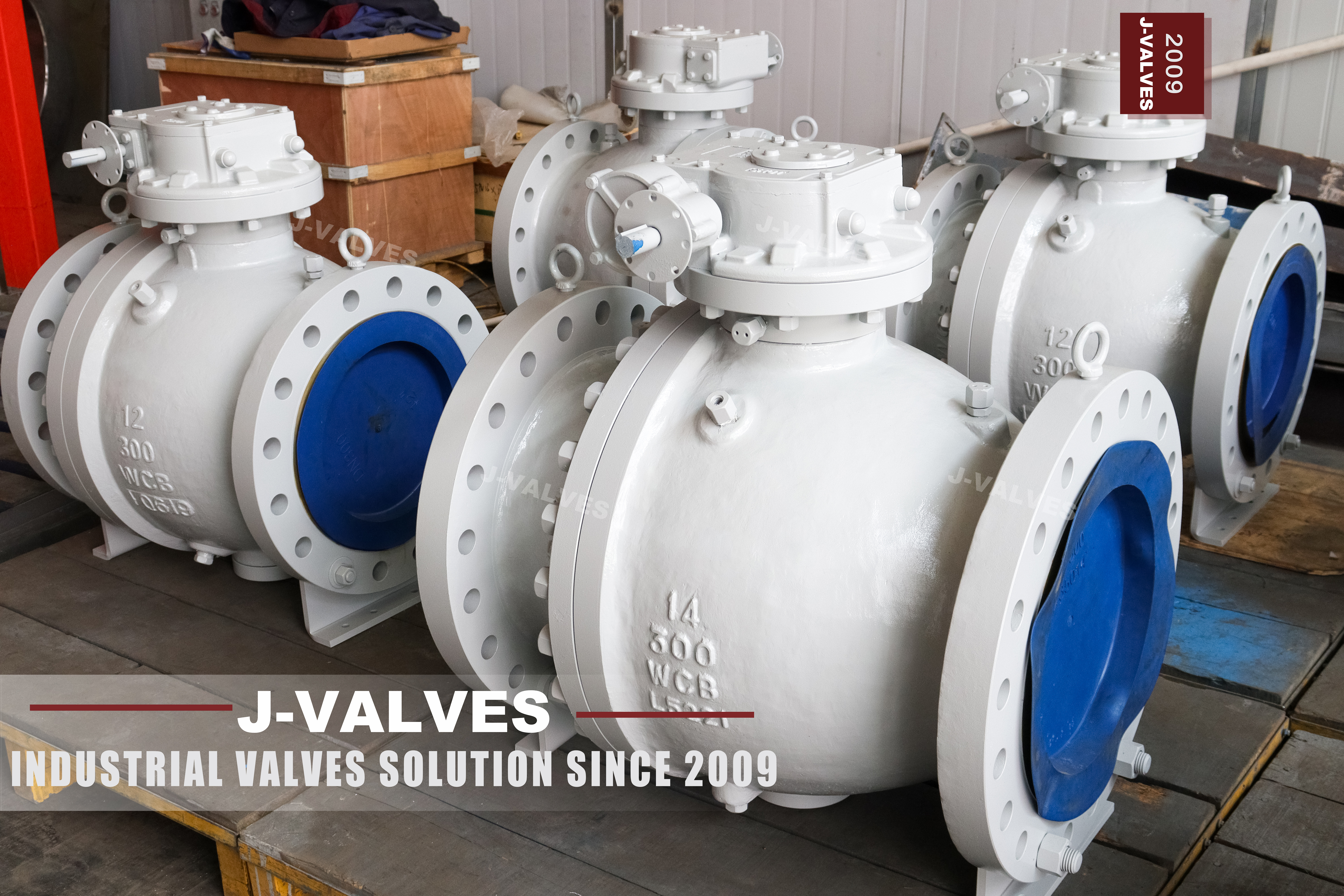
A 14 inch Class 300 two-piece trunnion ball valve in A216 WCB is a large bore isolation valve for ASME pipework, full bore so a pig can pass, with one bolted body joint and a gear operator. J-VALVES marks it PN50, the code API 6D clause 7.2 assigns to Class 300, and supplies it with raised face or ring type joint flanges to B16.5.
Fourteen inch is DN350, one of the two or three sizes that carry most transmission and station piping. It sits inside the range where B16.5 still applies, so the flanges are a catalogue item rather than a special, and it is large enough that the ball has to be carried on trunnions rather than float. Full bore is what makes it a line valve instead of a branch valve: a pig has to travel through it without meeting a ledge.
This page is organised around one split that matters more than any single feature. About half of what a buyer needs to check on this valve is tabulated in a standard and can be verified from a catalogue. The other half exists only on the drawing, and the largest item in that second half is the joint that holds the two body halves together. Reading the two halves separately is what separates a quotation that can be audited from one that cannot.
Design and Construction
The two-piece body divides along a plane across the bore. The main body carries the stem bore, both trunnion bearing blocks, one seat ring and the machined joint face. The end cap carries the second seat ring and one flanged end, and closes the bore. Every pressure boundary on this valve is therefore one of three things: a flange connection to the pipe, a seat, or that single joint.
The ball is carried on an upper and a lower trunnion, both running in metal backed self-lubricating bearings. Line pressure pushes the ball along the axis of the bore, and the trunnions take that load into the body instead of passing it to the seats. The stem therefore transmits torque only. This is the reason a 14 inch valve can be turned by hand through a gearbox rather than needing an actuator: the torque does not grow with the square of the bore the way it does on a floating valve.
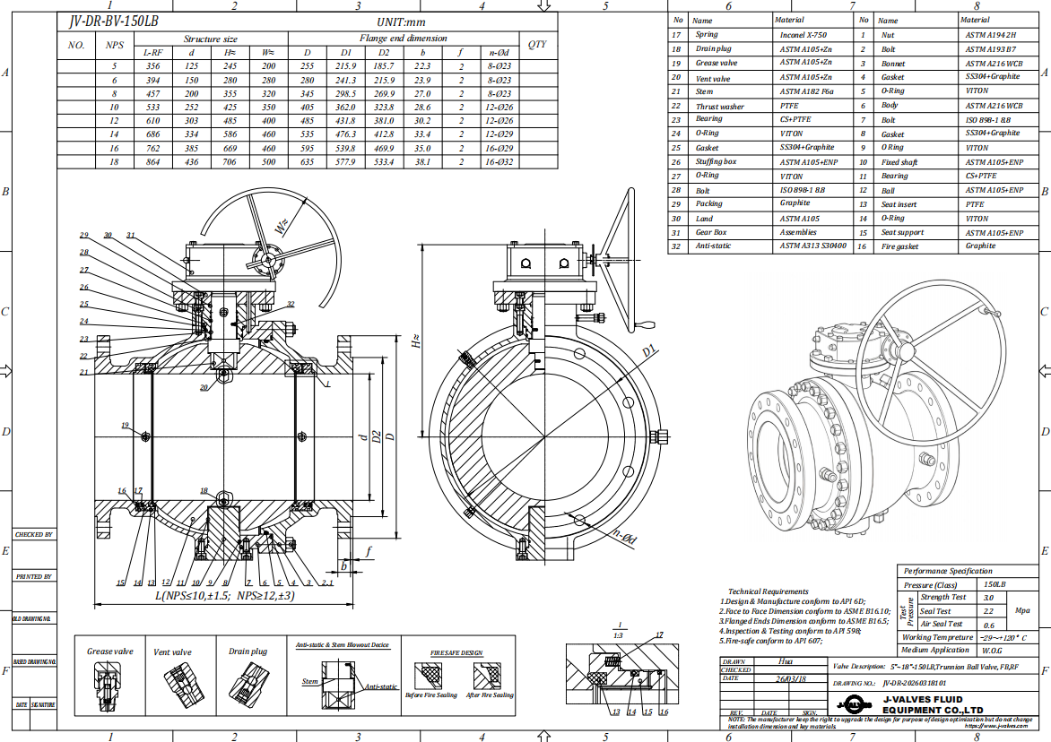
Then there is the joint, and it is worth being blunt about where it comes from. ASME B16.34 tabulates the shell wall for every size and class. ASME B16.10 gives the face to face. ASME B16.5 gives the flange outside diameter, the bolt circle, the bolt count, the bolt size and the facing. API 6D requires the body joint to be as strong as the shell and to be proven by calculation or test. **None of those documents tells you how many bolts the joint has, what size they are, what gasket sits in it, or how thick the two flanges are.** That is a design decision, made by the manufacturer, checked against the strength rules, and frozen on the drawing.
The practical consequence is uncomfortable but useful: two valves both marked 14 inch Class 300 can have body joints that share nothing. One may use a spiral wound gasket on a raised face with a ring of studs; another may use an O-ring in a groove with a much smaller bolt circle, relying on metal-to-metal contact to stop the halves moving. Both can pass the same hydrostatic test. Only one of them will still be sealing after ten thermal cycles.
So the joint cannot be accepted on the strength of the nameplate. It is accepted from the drawing, and from three questions put to the supplier. How many bolts, and of what grade. What gasket, and is it confined. What surface finish and flatness the two faces are machined to. A supplier who cannot answer those three from a drawing is asking to be trusted rather than checked.
Inside, the seats are soft seated as standard on a Class 300 valve. PTFE or reinforced PTFE is the normal choice, with PPL where the temperature runs higher. A metal seat with hardfacing is available and is the right answer for abrasive service or for a valve that is cycled often, but on clean gas or oil at moderate temperature the soft seat gives a tighter shutoff and is the cheaper of the two.
Full bore here means the bore meets the minimum internal diameter in Table 1 of API 6D for this size and class, not that it equals a nominal figure. The actual machined bore is a drawing dimension, and it is the number a pigging contractor will want to see before accepting the valve.
Material Options
| Component | Standard Material | Optional Upgrade | Service Notes |
|---|---|---|---|
| Body and end cap | ASTM A216 WCB cast carbon steel | A352 LCB for low temperature | Cast from the same heat where the order allows |
| Body joint gasket | Spiral wound, graphite filler | O-ring in groove, metal to metal faces | Gasket form is a design choice, not a standard item |
| Body joint bolting | ASTM A193 B7 studs with A194 2H nuts | B7M for NACE service | Grade and certificate belong in the order |
| Ball | A105N forging or WCB casting, ENP | Hard chrome, or 316 overlay | Forging and casting carry different certificates |
| Ball seats | PTFE | RPTFE, PPL, metal with hardfacing | The seat, not the body, caps the temperature |
| Stem | 17-4PH stainless | 316 stainless | 17-4PH is limited to 22 HRC under NACE |
| Trunnion bearings | Metal backed, self-lubricating | PTFE and graphite composite | Bearings are a wear item on a large valve |
| Flange facing | Raised face to B16.5 | Ring type joint to B16.5 | RTJ rings are bought separately |
A216 WCB is the default body material at this class and there is no reason to complicate it. It is a cast carbon steel in Group 1.1 of ASME B16.34, so its pressure temperature ratings come straight from the table, and its cost per kilo is the lowest of any material that will hold this pressure. The alternative that actually gets specified is A352 LCB, and it is specified for cold, not for corrosion.
The ball is where the material list tends to be written loosely. The old sheet offers A105N or WCB, and those are not the same thing. A105N is a forging; WCB is a casting. Both are carbon steel and both will take electroless nickel plating, but their certificates differ, and a buyer who needs an all-wrought valve has to say so at the order stage. On this size the ball is usually a casting with a machined and plated surface, because a forging of that diameter is expensive and slow.
The stem is 17-4PH precipitation hardening stainless, which is the right choice for torque and for galling resistance. It is also the one place where NACE MR0175 bites: the standard caps 17-4PH at 22 HRC, and a stem that has been hardened past that cannot be supplied for sour service whatever the body material is. If the line is sour, say so early, because the answer may be a different stem grade rather than a different body.
Technical Specifications
| Item | Value | Basis |
|---|---|---|
| Nominal size | 14 inch, DN350 | Nameplate |
| Pressure class | Class 300, recorded as PN50 | API 6D clause 7.2 |
| Rating at 100 F | 740 psi | ASME B16.34 Group 1.1 table |
| Temperature range supplied | -29 C to +425 C | J-VALVES range, both ends argued below |
| Body material | ASTM A216 WCB | Casting certificate, EN 10204 3.1 |
| Bore | Full bore, minimum per API 6D Table 1 | Actual bore on the GA drawing |
| Flange | NPS 14 Class 300, RF or RTJ | ASME B16.5 |
| Face to face | Per ASME B16.10 for this size and class | Value on the GA drawing |
| Body joint | Bolted, one joint, design determined | GA drawing only, no product standard |
| Design standard | API 6D, ASME B16.34 | Not API 608, see below |
| Test standard | API 6D and API 598 | Shell and seat test |
| Operator | Worm gear, handwheel | Actuator mounting to ISO 5211 |
The rating is a table value and nothing else. Class 300 in Group 1.1 reads 740 psi at 100 F in ASME B16.34, and the metric table in the same standard carries the equivalent entry at 38 C. Both are printed numbers; neither is a conversion done here. Anyone quoting a different figure for WCB at ambient is quoting something other than the standard.
The two ends of the temperature range have different origins, and that is worth knowing because it changes what you can do at each end. The lower end, -29 C, is where the Group 1.1 allowable stress curve in B16.34 begins. Below it the standard stops, which is a statement about the table rather than about the steel.
The upper end, +425 C, is not the B16.34 limit either: the table runs on to 538 C for carbon steel. What sits at 425 C is the 800 F line that pipe codes use as the point where carbon steel needs watching for graphitization, the slow breakdown of carbides into graphite that leaves the metal brittle without changing its appearance. So the supplied range runs from the start of the standard curve to just under the graphitization threshold. That is a defensible pair of numbers; it is not the same as "carbon steel is good to 425 C".
A second point about the cold end, which suppliers rarely volunteer: A216 WCB is a tensile tested casting, and Charpy impact is not part of the routine test. Marking a valve -29 C says the pressure rating is defined there. It does not say the casting has measured toughness at that temperature. If the line actually runs near the cold end, or if the buyer's specification asks for impact values, the choice is to call for Charpy testing as a supplementary requirement or to order the bodies in A352 LCB, which is the low temperature carbon steel grade and is tested for it.
The flange decision is not a pressure decision. Both facings are rated for Class 300, so the choice between raised face and ring type joint is about thermal cycling and about how much the joint will be disturbed. A raised face joint seals by compressing a gasket, and every thermal cycle takes some of that compression out; on a line that is started and stopped often, the bolts need retightening and eventually the joint weeps.
A ring type joint seals by trapping a metal ring in a groove, with the bolt load holding the ring rather than squeezing a soft material, and it tolerates cycling much better. The price is that the ring is a separate purchase, it is used once, and the groove has to be protected from the moment the valve leaves the crate until the joint is closed.
Standards and Compliance
| Requirement | Standard | What It Covers |
|---|---|---|
| Valve design and manufacture | API 6D | Trunnion ball valves for pipeline service |
| Pressure temperature rating | ASME B16.34 | Group 1.1 table for WCB, wall thickness by size and class |
| Flange dimensions | ASME B16.5 | NPS 14 Class 300, RF and RTJ, up to NPS 24 |
| Face to face | ASME B16.10 | End to end for this size and class |
| Shell and seat test | API 6D, API 598 | Shell at 1.5 times rating, seat at 1.1 times |
| Fire test | API 607, ISO 10497 | Certification of the design, not of each valve |
| Anti-static | API 6D | Electrical continuity between ball, stem and body |
| Body joint | No product standard | Strength proven to B16.34 rules, dimensions on the drawing |
| Stem sealing | ISO 15848 | Fugitive emission class, where specified |
One line in that table is the whole argument of this page. Every other row can be checked by opening a standard and finding a number. The body joint row has no number to find.
API 608 belongs on floating ball valves, not here. The old sheet lists it alongside API 6D, which reads as though the valve were built to both. A 14 inch trunnion valve is an API 6D product; API 608 stops where trunnion construction begins, and a data sheet carrying both invites the question of which one the test report will follow.
Manufacturing Process
Both halves are cast from the same heat whenever the order allows, and the heat number is carried on both castings. This is not a formality. Two halves of different chemistry machine differently, stress relieve differently and move differently after the joint is torqued, and the joint is the one place on this valve where that movement shows up as a leak.
The joint face is the most demanding machining on the valve. It has to be flat across a diameter larger than the bore, it has to be square to the bore axis, and the bolt holes have to line up with the mating holes without the studs being used to pull the halves into position. On a 14 inch body that face is machined on a vertical borer or a large horizontal, and flatness is checked rather than assumed.
Where the size of the part allows, the joint face and the bore are machined in one set up, so that squareness between the two is a machine result rather than something corrected at assembly. Where it cannot be done in one set up, the face is checked against the bore axis with a dial indicator before the halves are brought together. The ball is machined, ground and plated, and the plating thickness is held because it changes the ball diameter and therefore how hard the seats are squeezed when the valve closes. Assembly ends with the joint torqued in a crossing pattern to a figure taken from the bolt grade and the gasket, and that figure goes on the drawing rather than being left to the shop floor.

Quality Control and Testing
| Check | Method | Acceptance |
|---|---|---|
| Chemical and mechanical properties | Heat analysis and tensile test | A216 WCB, certificate with heat number |
| Casting integrity | Visual, plus RT or UT where specified | No defect in the pressure boundary |
| Shell wall | Ultrasonic thickness | Not below the B16.34 minimum for the class |
| Joint face | Flatness and surface finish | Within the drawing tolerance before assembly |
| Joint bolting | Material certificate | Grade as ordered, B7 or B7M |
| Shell test | Hydrostatic at 1.5 times rating | No leak, no permanent deformation |
| Seat test | Hydrostatic at 1.1 times rating, each side | No visible leakage on a soft seat |
| Anti-static | Resistance across ball, stem and body | Continuity recorded at assembly |
| Functional | Gear operation, open and closed | Torque within the drawing figure |
Nine checks, and two of them concern the joint rather than the bore. That ratio is deliberate. The bore, the ball and the seats are the parts everyone inspects, and they are also the parts a competent shop gets right. The joint is where a valve that looks correct on the outside passes its works test and still weeps six months later.
The bolting certificate is the item most often left off an order and the one that decides how the joint behaves. A193 B7 studs and A194 2H nuts are the default, and B7M is the sour service variant; the two are not interchangeable and the difference is not visible once installed. If the joint is to be accepted, the stud grade on the certificate has to match the grade on the drawing.
Non-destructive testing on a casting this size follows the purchase specification rather than a default. Radiography of the body and end cap, ultrasonic examination of the wall, or dye penetrant on the machined joint face are all available, and each adds cost and lead time. The sensible position is to specify the examination that matches the consequence of a leak: a 14 inch Class 300 gas valve in a station deserves radiography of the pressure boundary, a water line in a plant may not.

Applications and Industry Service
The natural duty for a 14 inch full bore trunnion valve is a transmission or station line where the bore has to stay clear. Pigging is the reason full bore exists at this size: a cleaning or inspection pig has to run from one end of the line to the other, and any valve on that route has to pass it without a ledge, a step or a reduction. A reduced bore valve at this size is a deliberate obstruction in a line that is otherwise continuous.
The second duty is station piping, where the valve isolates a meter run, a filter bank, a regulator or a pig trap. Here the requirement is different: the valve is operated rarely, it must seal tightly when closed, and it is often the boundary that lets maintenance happen on the other side. A soft seated valve is the right answer for that, which is why most station valves at this class are soft seated and why the metal seat option is reserved for the lines that actually need it.
It is worth saying where this valve is the wrong purchase. A line that is cycled daily, or that carries solids, will wear a soft seat and should be a metal seated valve, accepting the leakage class that comes with metal contact. A line above 425 C should be a different body material rather than this one on a technicality. And a line that has to be repaired with the pipe left in place, on a crowded skid with no room to withdraw an end cap, should be a top entry valve instead, because the two-piece body on this page needs that room.
Installation, Operation and Maintenance
Lifting is the first thing to get right and the first thing that goes wrong. The valve is lifted on slings around the body, never on the gearbox, the stem or the actuator mounting flange. The gearbox is a light casting bolted to the top of the stem and will not carry the valve; a sling there will bend the stem before the valve leaves the ground.
The end cap needs room to come out along the axis of the bore. On a 14 inch valve the cap is a heavy casting with a flange on it, and it has to travel clear of the studs and then be lifted away. If the downstream pipe runs straight into an elbow, a support or a wall, that space does not exist, and the only way to change a seat later is to cut the line. This is a drawing stage decision, and it is worth marking the withdrawal clearance on the arrangement drawing so that whoever lays out the skid sees it before the pipe is fabricated.
Commissioning is where the joint gets proved. With the valve closed and the cavity drain open, the cavity should empty and stay empty; if it fills, one of the seats is passing and the valve should not be accepted. Then close the drain, bring the line up to pressure with the valve closed, and check the joint for weeping at both the gasket and the studs. A joint that weeps at commissioning will not improve with time.
Maintenance means opening one joint. The gasket or O-ring is replaced rather than reused, the two faces are cleaned and checked for marking or fretting, and the halves are brought back together with the studs lubricated and torqued in the crossing pattern on the drawing. The seats and the ball can be reached once the cap is off, which is the commercial reason for the two-piece design: the pipe stays where it is, and the valve is repaired in place.
How to Specify and Order
Six answers settle the order, and they divide neatly along the line this page has followed. Size and class, flange standard and facing, and the pressure temperature rating are all tabulated: 14 inch, Class 300, B16.5 with either facing, 740 psi at 100 F in Group 1.1. Bore, body joint and operator are not tabulated. Full bore to API 6D Table 1 or reduced; the joint as designed, which has to be seen on the drawing; and a gear operator, with the actuator mounting flange to ISO 5211 if a quarter turn actuator is planned later.
The quotation is issued against the data sheet with a general arrangement drawing for the size and class ordered. That drawing carries the numbers no standard supplies: the bore actually machined, the face to face, the joint bolt count and grade, the gasket form, the torquing figure, and the end cap withdrawal clearance. Two of those items, the bolt grade and the gasket form, are also worth writing into the purchase order text, because they are the two things a works test will not reveal and a leak will.
A valve of this size is bought once and lived with for twenty years. The flange dimensions will be right whatever supplier is chosen, because B16.5 does not vary. The joint is where suppliers differ, and it is the only part of the purchase that has to be argued from a drawing rather than looked up.
FAQ
Q: Why is there no standard dimension for the body joint?
A: B16.34 tabulates the shell wall, B16.10 the face to face and B16.5 the flange, but none of them sizes the joint that holds the two halves together. API 6D requires that joint to be as strong as the shell and to be proven by calculation or test, and leaves the bolt count, the bolt grade, the gasket form and the flange thickness to the manufacturer. Two valves both marked 14 inch Class 300 can therefore have joints that share nothing, and both can pass the same hydrostatic test. Put the bolt grade and the gasket form into the purchase order and check them against the GA drawing.
Q: Where do -29 C and +425 C come from?
A: From two different places, meaning two different things. -29 C is where the Group 1.1 allowable stress curve in ASME B16.34 starts, so it is the bottom of the table rather than a property of the steel. +425 C sits just under the 800 F line where pipe codes call for carbon steel to be watched for graphitization, while B16.34 itself runs on to 538 C for this group. The supplied range is therefore the start of the standard curve to just below the graphitization threshold, not a claim that carbon steel is good to 425 C in any service.
Q: Can A216 WCB be used at -29 C?
A: It can be rated there, which is not the same as being tough there. A216 WCB is a tensile tested casting and Charpy impact is not part of the routine test, so a nameplate reading -29 C says the pressure rating is defined at that temperature and says nothing about measured toughness. If the line runs near the cold end, or if the specification asks for impact values, order the bodies in A352 LCB, the low temperature carbon steel grade, or call for Charpy testing as a supplementary requirement.
Q: Two-piece, three-piece or top entry?
A: The two-piece body has one joint, and the end cap has to come out along the axis of the bore, which is a layout decision made on the drawing rather than on site. A three-piece body has two joints, both in a centre section that never has to move, and is easier to repair on a crowded skid. A top entry body is repaired from above through the bonnet, which suits a valve that would otherwise need the line cut. At 14 inch Class 300 the two-piece is the least expensive of the three, and the choice turns on repair access rather than on pressure.


Hot Products


News
Ball Valves in Geothermal Brine: Silica Scale, Chloride Cracking And The Cooling Trap
Why geothermal brine destroys ball valves: retrograde silica scale, calcite at the flash point, chloride cracking above 60 C and the 250 C seat limit.
Read More
Ball Valve Face To Face Dimensions: Why A Correctly Ordered Replacement Still Does Not Fit
A 6 inch Class 150 ball valve can be 267 or 305 mm face to face and both are compliant. How B16.10, EN 558 and flange drilling decide whether it fits.
Read More
Ball Valve Stem Key And Keyway: What Gives Way First, And What The Handle Cannot Tell You
Between the handle and the ball there are four fits. Which one shears, which one cracks, and how a few degrees of lost motion hides a valve that never seated.
Read More
Ball Valve Datasheet: Six Blocks That Decide Whether Two Quotes Are Comparable
A ball valve datasheet only works when six blocks are fixed: pressure basis, bore, temperature ceiling, test, end connection, operator. How each is written.
Read More