


CHINA J-VALVES Offers Various High-quality I ndustrial Ball Valves
J-VALVES, a distinguished professional ball valve manufacturer rooted in China, takes pride in its extensive product portfolio. Our offerings span a wide range, including trunnion-mounted ball valves, floating ball valves, high-temperature ball valves, high-pressure ball valves, metal-sealed ball valves, ultra-low temperature ball valves, DBB ball valves, Three-way And Four-way Ball Valve, and fully welded ball valves. Each product is a testament to our commitment to precision engineering and reliable performance. Meticulously crafted, they are designed to not only meet but exceed the most stringent industrial demands, ensuring stable operation even under extreme conditions. This enables us to provide our clients with high-value services and makes our valves widely sought-after in industries.
Product Category
Contact Us


-
J-VALVES-Q47F
-
J-VALVES
Overview of the J-VALVES 6 x 4 Inch Class 300 Reduced Bore Trunnion Mounted Ball Valve
The 6 x 4 inch Class 300 reduced bore trunnion mounted ball valve is a 6 inch flanged valve carrying a 4 inch bore. The ends are 150 mm ASME B16.5 Class 300 flanges, the shell is a two piece bolted ASTM A216 WCB body, and the passage through the ball measures 100 mm. The ball runs on upper and lower trunnions in metal backed bearings rather than hanging from the stem.
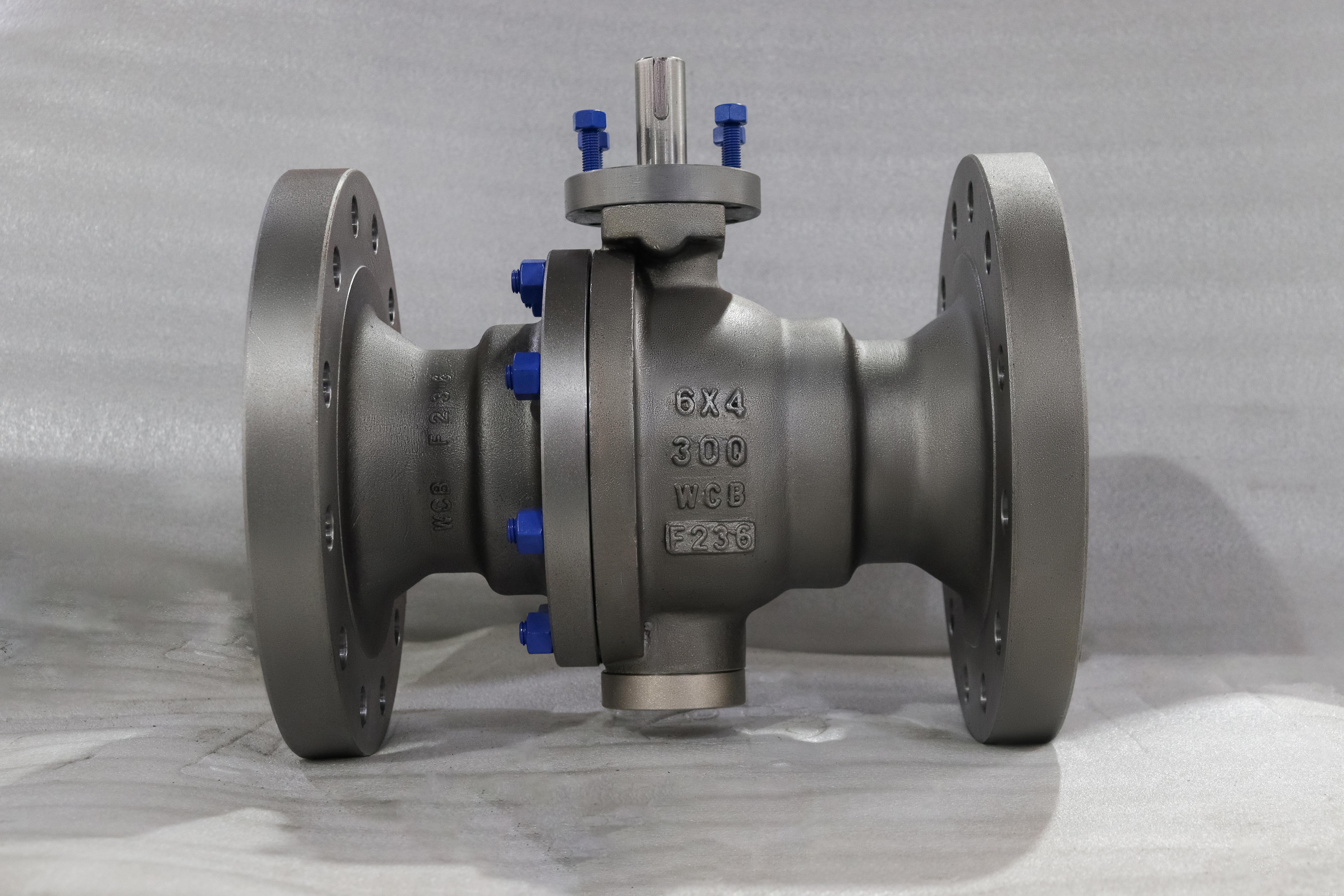
The first number is the valve and the second is the bore, and that order d
ecides how the valve is bought and installed. Dimensionally this is a 6 inch valve throughout:
flanges, bolt circle, face to face length and body casting all follow NPS 6, and only the ball, seats and seat pockets are cut to NPS 4. API 6D allows this directly, permitting reduced opening valves up to NPS 12 to carry a bore one nominal size below the valve size, provided that bore meets the Table 1 minimum for the smaller size, which for NPS 4 is 100 mm.
What the reduction buys is mass and torque. The ball, both seat rings and the cavity around them shrink with the bore, so a 6 x 4 typically weighs 20 to 35 percent less than the full bore valve of the same size and class, and breakaway torque falls far enough that the gearbox and any later actuator can be one frame smaller. What it costs is paid in three places. At the same flow the 100 mm bore runs the fluid about 2.3 times faster than a 152 mm bore, and pressure drop is roughly 3.2 times higher because the flow coefficient falls from about 1,700 to about 950. Pigging is different in kind: a 6 inch pig cannot enter a 100 mm bore, so the valve belongs on branch takeoffs, drains, vents, bypasses and proving loops, never on a line that may be cleaned, gauged or inspected by pig.
Design and Construction
The body is a two piece bolted split, a main body and a closure joined on one machined face with a spiral wound stainless and graphite gasket and a ring of A193 B7 bolts. That joint is the only pressure boundary remade in the field, and the split sits at the 6 inch end, so with the closure removed the ball, both seat rings and both trunnion bearings withdraw through the 6 inch opening in one piece. On a true 4 inch valve that work would need the line cut, so the reduced bore gives up flow area and gains an access route the smaller valve never had.
The ball has trunnions at top and bottom, each in a metal backed PTFE and graphite bearing. At the 38 C rating of 51.1 bar the line pressure puts about 40 kN of hydrostatic end load on the ball face and the trunnions carry all of it, so the stem transmits torque only and the seats see nothing but their own spring and piston load. The same valve in full bore presents about 93 kN to the same bearings, so the 6 x 4 can use a smaller trunnion, bearing and operator. That, more than bore area alone, is where the torque saving comes from.
Seats are single piston effect as standard, double piston effect on request. An SPE seat is pushed onto the ball by pressure on its upstream face and pulled away on its downstream face, so pressure trapped in the cavity by thermal expansion escapes into the lower pressure side without an external device. A DPE seat is pushed on from both sides, giving double isolation both ways and a second barrier if one seat is damaged, but the cavity then needs an external relief device on liquid service. The insert sits in a metal carrier loaded by coil springs, so the valve seals at low pressure on spring force and at high pressure on the piston area behind the insert.
The stem is 17-4PH stainless, retained by the body so pressure cannot eject it, in the arrangement API 6D requires. Two O-rings and a graphite gasket form a triple barrier, and the graphite element is what keeps the stem tight after a fire has consumed the elastomer. A spring loaded plunger bonds ball to stem to body for static discharge, and the arrangement is fire safe to API 607 and ISO 10497. An NPT vent and drain in the lower body completes the double block and bleed function: with the ball closed the cavity can be vented and each seat checked independently.
Material Options
The F236 in the designation is the fluoroelastomer compound used for the seat inserts and secondary seals, not a body or trim grade. It is a 66 to 70 percent fluorine FKM chosen for oil, hydrocarbon and high temperature service, and it is why this valve is not a general purpose steam valve. FKM holds a continuous 204 C with a floor near -20 C, hydrolyses in steam above roughly 150 C, and swells in ketones, esters and amines. Where any of those apply the seat moves to RPTFE, PEEK or a Stellite faced metal seat.
| Component | Standard Material | Optional Upgrade | Service Notes |
|---|---|---|---|
| Body and closure | ASTM A216 WCB cast carbon steel | A352 LCB, A351 CF8M | Group 1.1, -29 C to 425 C on the shell |
| Ball | ASTM A105N forged, hard chrome plated | F316 with ENP, F51 duplex | Chrome 0.05 to 0.10 mm at 800 to 1000 HV |
| Stem | 17-4PH stainless steel | F316, F51 | Anti-blowout, retained by the body |
| Seat insert | FKM, F236 compound | RPTFE, PEEK, Stellite 6 | FKM limited to 204 C, unsuitable for steam |
| Seat ring carrier | A105 with ENP | F316, F51 | Piston area sets seat load at pressure |
| Trunnion bearing | PTFE and graphite, metal backed | PEEK composite | Carries the 40 kN ball end load |
| Body gasket | Spiral wound 316L with graphite | Ring joint on RTJ ends | Renewed whenever the joint is opened |
| Body bolting | A193 B7 studs with A194 2H nuts | A320 L7 for low temperature | Torque and sequence per the drawing |
| Stem seals | FKM O-rings with graphite packing | PTFE, FFKM | Triple barrier, ISO 15848-1 |
WCB is the default because the envelope of a Class 300 carbon steel valve covers most branch duty. Upgrading to CF8M does not raise the pressure class; it changes the corrosion allowance, and the rating curve stays the property of ASME B16.34 group 2.2 rather than group 1.1.
Technical Specifications
The table describes the standard build. Values move when the seat grade, flange facing or operator changes, but the face to face length is fixed by the 6 inch valve size rather than the 4 inch bore.
| Item | Value |
|---|---|
| Nominal size | 6 x 4 inch, DN150 x DN100 |
| Bore type | Reduced bore, one size below nominal per API 6D 6.2.2 |
| Bore diameter | 100 mm |
| Pressure class | ASME Class 300, designated PN 50 in API 6D |
| Body material | ASTM A216 WCB |
| Body style | Two piece, side entry, bolted |
| End connection | ASME B16.5 Class 300, RF or RTJ |
| Flange outside diameter | 317.5 mm |
| Flange bolt circle | 269.7 mm, 12 bolts of 3/4 inch |
| Face to face length | 403 mm per ASME B16.10 |
| Pressure rating at 38 C | 51.1 bar |
| Pressure rating at 425 C | 38.0 bar, shell limit only |
| Temperature range as built | -20 C to 204 C, set by the FKM seat |
| Seat design | Single piston effect standard, double optional |
| Breakaway torque | 250 to 500 N m reference, measured per valve |
| Operator | Worm gear, ISO 5211 mounting flange |
| Anti-static | Spring loaded plunger, ball to stem to body |
| Fire safe | API 607 and ISO 10497 |
| Design standard | API 6D with ASME B16.34 |
| Test standard | API 6D clause 11 and API 598 |
The gap between the 51.1 bar rating and the 204 C limit is where quotations usually mislead. The shell is a Class 300 WCB casting good for 38.0 bar at 425 C, but the seat in this build is FKM, and no elastomer seat survives there.
Standards and Compliance
The design basis is API 6D, the pipeline valve specification, which defines the reduced opening rule this valve is built to, the double block and bleed requirement, the anti-blowout stem, the 1.5 times shell test and the fire qualification. API 608 also appears on many quotations and is the wrong basis: it is a general industrial standard carrying neither the bore table nor the pipeline test regime this valve is bought against.
PN 50 needs care, though not for the reason usually given. API 6D itself designates Class 300 as PN 50, so the label is correct on a valve data sheet. It is not an EN 1092-1 rating, and EN 1092-1 has no PN 50 step, running from PN 40 straight to PN 63. The consequence is at the mating flange. A Class 300 NPS 6 flange is 317.5 mm across with a 269.7 mm bolt circle and 12 bolts of 3/4 inch; the nearest EN flange, PN 40 DN150, is 300 mm across with a 250 mm circle and 8 bolts of M26.
Face to face follows ASME B16.10 for the 6 inch valve and measures 403 mm. This belongs on the order because the 4 inch valve of the same class is only 305 mm long, and a factory that builds to the bore rather than the valve size produces a body that will not fit the spool.
| Requirement | Standard | Supplied |
|---|---|---|
| Design and pressure containment | API 6D, ASME B16.34 | Group 1.1 carbon steel |
| Reduced bore definition | API 6D 6.2.2 and Table 1 | 100 mm bore in a 150 mm valve |
| Face to face | ASME B16.10 | 403 mm |
| Flange dimensions | ASME B16.5 Class 300 | RF or RTJ, 12 bolt |
| Shell test | API 6D clause 11, 1.5 times rating | 76.7 bar hydrostatic |
| Seat test | API 6D clause 11, 1.1 times rating | 56.2 bar both directions |
| Fire safe | API 607, ISO 10497 | Certified |
| Fugitive emission | ISO 15848-1 | Triple stem barrier |
| Sour service | NACE MR0175, ISO 15156 | On request, hardness controlled |
| Material certification | EN 10204 3.1 | Included |
Manufacturing Process
Bodies and closures are cast to A216 WCB and machined at the J-VALVES plants in Wenzhou and Lishui, on a 15000 square metre base running 40 CNC lathes, 5 machining centres and 8 drilling machines. The bore, seat pockets, trunnion bores and both flange faces are cut against the drawing, because the alignment between the upper and lower trunnion bearings governs how freely the ball turns and therefore what torque the operator sees.
The reduced bore adds one operation a full bore valve does not need. Because the shell is sized for NPS 6 and the trim for NPS 4, the transition from the 150 mm flange bore to the 100 mm seat throat is machined as a controlled taper rather than left as a step. A sharp step there becomes the point where velocity is highest and erosion starts, so the taper is blended and inspected. The ball is turned, ground and hard chrome plated before lapping to the seat.

Quality Control and Testing
Every valve is pressure tested on the bench and its breakaway torque recorded before painting and packing.
| Step | What Is Checked | Standard or Acceptance |
|---|---|---|
| Incoming material | Chemistry and mechanicals of the WCB heat | EN 10204 3.1 certificate |
| Dimensional | Bore, face to face, flange drilling, seat pocket | Drawing, 403 mm face to face |
| Non destructive | Radiography or dye penetrant on castings | ASME B16.34 as ordered |
| Hydrostatic shell | Body and joint at 76.7 bar | No leakage or distortion |
| Seat test | 56.2 bar each seat, both directions | Zero visible leakage, soft seat |
| Torque | Breakaway and running torque recorded | Against the torque record |
| Functional | Open and close cycles, vent and drain | Full quarter turn, no binding |
| Final | Painting, marking, packing | RAL 5015, bore plugged |

Applications and Industry Service
The natural application is a branch takeoff. Where a 6 inch header feeds a 4 inch branch, a 6 x 4 valve does the work of a 6 inch valve, a 6 x 4 reducer and a 4 inch valve in one 403 mm gap, with two flanged joints instead of four. It mates with the header flange while matching the branch bore, which is why it is dimensioned as a 6 inch valve.
The second group is intermittent utility duty. Drains, vents, blowdown, sample points, pump bypass and control valve bypass run occasionally, tolerate a pressure drop and never see a pig, which is the envelope where reduced bore costs nothing and saves weight, torque and money.
The third is proving loops, but only downstream of the meter. A reduced bore should not sit upstream of a turbine, ultrasonic or Coriolis meter, because the taper disturbs the flow profile the meter needs, and not on pump suction where the added loss invites cavitation.
Installation, Operation and Maintenance
Before installation, confirm the face to face dimension against the spool, clean both flange faces and the bore, and cycle the valve once. The valve is bidirectional so it fits either way round, but the gear operator should end up accessible from the walkway, and a valve of this mass needs its own support rather than hanging on the flange bolts.
Operation is quarter turn and either fully open or fully closed. A reduced bore valve throttles badly: the taper that makes it economical at full flow becomes an erosion point at part open. Isolation follows the double block and bleed sequence. Close the valve, open the cavity vent, confirm the cavity drains and neither seat passes, then work downstream. On a DPE build the cavity must never be left liquid filled and blocked in without a relief path.
To replace the seats, isolate the line, vent and drain both sides, confirm the cavity is depressurised, then break the body joint. Both seats are renewed as a set, the gasket is replaced, and the bolts retightened to the specified torque and sequence. Because the trim withdraws through the 6 inch end no line cutting is needed, but the spool must be long enough to slide the closure clear.
How to Specify and Order
State the size as 6 x 4 inch with the bore in millimetres, not as 6 inch, because a supplier who reads only the first number will quote a full bore valve and one who reads only the second will build a 4 inch body. Give the class, the facing as RF or RTJ, the 403 mm face to face length, and the seat elastomer with design temperature. If the line may ever be pigged, specify full bore instead.
Also state the medium, operating temperature, whether NACE MR0175 applies, the operator and, for actuated valves, the available air or power supply. J-VALVES supplies the EN 10204 3.1 certificate, dimensional report, pressure test report with torque records, painting report and packing list with each shipment. Standard builds ship from one piece, 2 to 4 weeks for standard and 4 to 8 for special trim.
FAQ
Q: What does 6 x 4 mean on a ball valve?
A: The first number is the valve size and the second is the bore. A 6 x 4 valve has 6 inch ASME B16.5 Class 300 flanges on a 6 inch body, but the ball passage is 100 mm, the NPS 4 minimum in API 6D Table 1. It bolts into a 6 inch line and passes the flow of a 4 inch one.
Q: Can a 6 x 4 reduced bore valve be pigged?
A: No. A 6 inch pig cannot enter a 100 mm bore, so the valve cannot be used on any line that is cleaned, gauged or inspected by pig. Use the full bore 6 inch valve for mainline and piggable service, and keep the reduced bore for branches, drains, vents and bypasses.
Q: Why is the valve rated -20 to 204 C when the body is good for 425 C?
A: The 425 C figure is the ASME B16.34 rating of the WCB shell. The FKM seat in this build holds 204 C continuously and has a floor near -20 C, so the seat sets the range of the valve as supplied. A PEEK or metal seated build raises the upper limit.
Q: Does a reduced bore valve have the same face to face length as a full bore valve?
A: Yes, when both are built as 6 inch Class 300 valves. ASME B16.10 gives 403 mm for NPS 6 at this class and the reduced bore does not change it. A valve built to the 4 inch dimension of 305 mm will not fit the spool.
Hot Products


News
Ball Valves in Geothermal Brine: Silica Scale, Chloride Cracking And The Cooling Trap
Why geothermal brine destroys ball valves: retrograde silica scale, calcite at the flash point, chloride cracking above 60 C and the 250 C seat limit.
Read More
Ball Valve Face To Face Dimensions: Why A Correctly Ordered Replacement Still Does Not Fit
A 6 inch Class 150 ball valve can be 267 or 305 mm face to face and both are compliant. How B16.10, EN 558 and flange drilling decide whether it fits.
Read More
Ball Valve Stem Key And Keyway: What Gives Way First, And What The Handle Cannot Tell You
Between the handle and the ball there are four fits. Which one shears, which one cracks, and how a few degrees of lost motion hides a valve that never seated.
Read More
Ball Valve Datasheet: Six Blocks That Decide Whether Two Quotes Are Comparable
A ball valve datasheet only works when six blocks are fixed: pressure basis, bore, temperature ceiling, test, end connection, operator. How each is written.
Read More