


CHINA J-VALVES Offers Various High-quality I ndustrial Ball Valves
J-VALVES, a distinguished professional ball valve manufacturer rooted in China, takes pride in its extensive product portfolio. Our offerings span a wide range, including trunnion-mounted ball valves, floating ball valves, high-temperature ball valves, high-pressure ball valves, metal-sealed ball valves, ultra-low temperature ball valves, DBB ball valves, Three-way And Four-way Ball Valve, and fully welded ball valves. Each product is a testament to our commitment to precision engineering and reliable performance. Meticulously crafted, they are designed to not only meet but exceed the most stringent industrial demands, ensuring stable operation even under extreme conditions. This enables us to provide our clients with high-value services and makes our valves widely sought-after in industries.
Product Category
Contact Us


-
J-VALVES-Q41F
-
J-VALVES
Overview of the J-VALVES 3 Inch 600LB WCB Two Piece Flanged Floating Ball Valve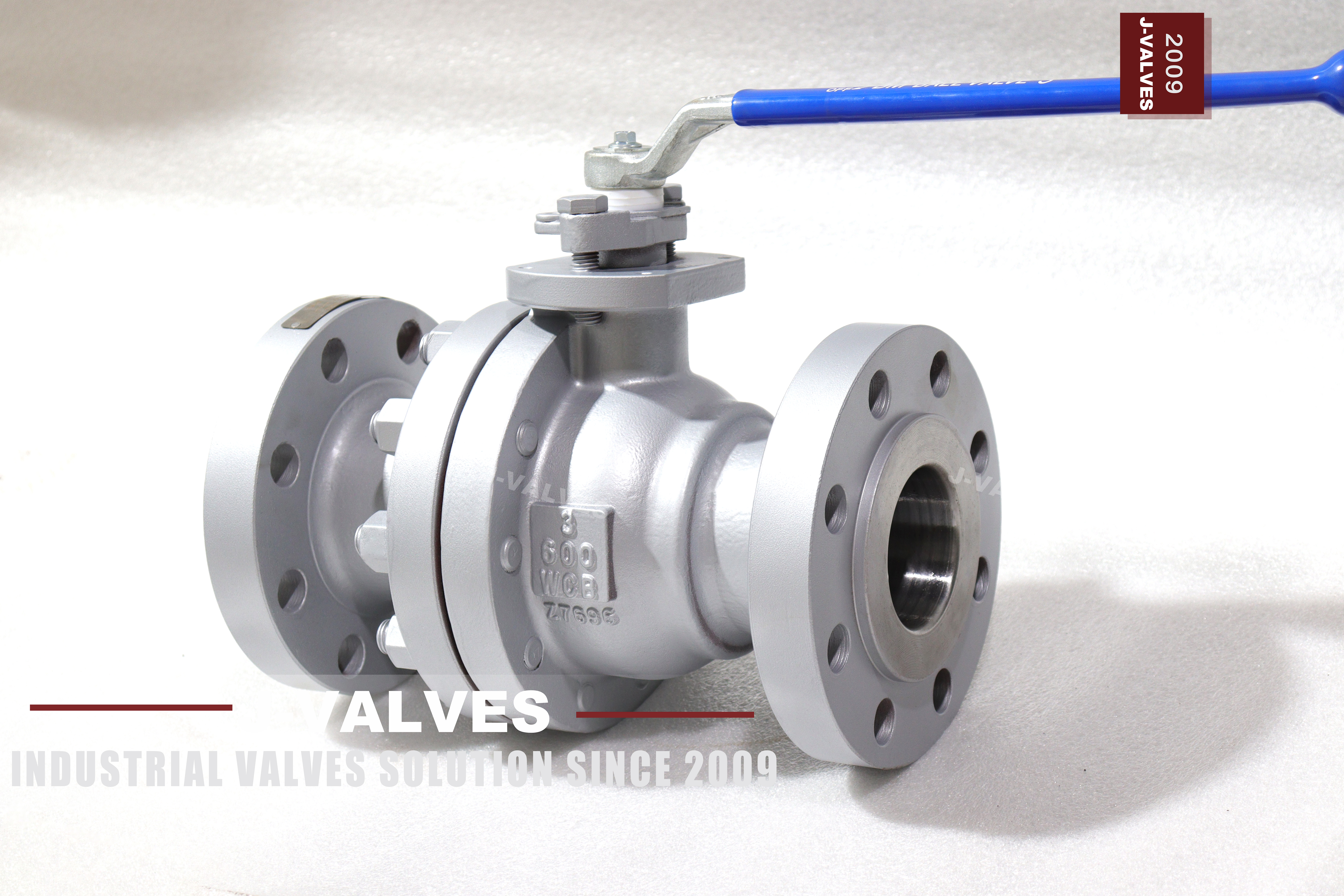
A three inch valve at Class 600 is a working size rather than a critical one, and that is exactly why it spends time in a warehouse. It is bought as a spare for a line that may not be shut down for two years, it sits on a shelf in its crate, and everybody assumes it is new because nobody has turned it. The parts that age in that time are not the ones the specification talks about: the casting does not change, the ball does not change, and the seat and the packing do.
Both of those are polymers held in compression. A seat is squeezed between the ball and the body pocket at assembly, and it stays squeezed while the valve sits. Over months that load produces a permanent deformation, which is why the first quarter turn after a long storage sometimes weeps before it seats again. Nothing about this is a defect; it is how the material behaves, and it is worth planning the shelf around it rather than discovering it at commissioning.
Design and Construction
The body is two cast halves joined at one bolted joint. That joint is the only place on the valve where the pressure boundary is made by bolts rather than by the material, and at Class 600 it is carrying a real load: the flange is heavy, the studs are large and the gasket between the halves has to hold the full rating. It is also the joint that has to come apart if a seat is replaced, which is the reason the spares list and the body design are the same conversation.
The ball floats between two seats and is pushed downstream by line pressure until it bears on the outlet seat. At three inches and six hundred pounds the seat load is high enough that the seat compound matters more than it does at Class 150, and low enough that the valve is still hand operated. The lever is a plain ninety degree handle with a locking hole; a gearbox is offered but is not needed until the size or the differential pressure goes up.

Material Options
The body is cast carbon steel, the WCB grade, which covers water, oil, gas and steam up to the temperature where carbon steel stops being the right answer. The ball is carbon steel with hard chrome plating or a stainless grade, and the stem is 17-4PH or 316. The grade behind the code is settled by the nameplate and the mill certificate rather than by a catalogue line, and on a casting the heat number is what ties the finished body to the pour.
The seat is where this valve is decided. PTFE is the standard answer and the one with the lowest temperature ceiling; reinforced PTFE and PPL each buy back some of that ceiling; nylon appears in some specifications as a secondary sealing material for lower pressure duty. A hardfaced metal seat is available as a different design, not as an upgrade to this one, and it is judged on leakage rate rather than on zero leakage. Which of those is right depends on temperature and medium, not on the pressure class.
| Component | Standard Material | Optional Upgrade | Service Notes |
|---|---|---|---|
| Body and side body | cast carbon steel, grade as stamped | the WCB casting grade | two pieces, one bolted joint |
| Ball | carbon steel with hard chrome plating | stainless grade | ground, then plated |
| Stem | 17-4PH stainless | 316 stainless | packing stays in the body |
| Seat | PTFE | reinforced PTFE, PPL or nylon | sets the service temperature |
| Packing | flexible graphite | PTFE | gland adjustable |
| Body gasket | replaced whenever the joint is opened | quoted with the seat kit | not reusable |
| Ends | raised face to ASME B16.5 | ring joint, a different valve | DN80 pattern |
Technical Specifications
The flange drilling is ASME B16.5 Class 600 at DN80, and the page offers either a raised face or a ring joint end. Those are two different valves: the ring groove is machined into the flange face and cannot be added on site, and the two ends take different gaskets, different stud lengths and different spanner access. Face to face is held to ASME B16.10 for a flanged valve of this size and class, and neither the length nor the flange dimensions are printed here as numbers for the reason that they belong to those tables.
What is worth printing is what the tables do not say. A Class 600 three inch flange is a heavy part relative to the body, so the valve is carried by the pipe rather than supporting it, and the pipe supports have to be designed for the flange pair rather than for a bare pipe. Anything that depends on the build, such as overall height with a gearbox or an actuator, is dimensioned on the signed general arrangement drawing for the size and trim ordered.
| Item | Value |
|---|---|
| Nominal size | 3 inch (DN80) |
| Pressure class | Class 600 (PN 100) |
| Body style | two piece, one bolted joint |
| Ball support | floating, no trunnion |
| Bore | full bore, DN80 |
| Body material | cast carbon steel, grade as stamped on the nameplate |
| Ball material | carbon steel with hard chrome plating, stainless grade optional |
| Stem | 17-4PH or 316 stainless |
| Seat | PTFE standard; reinforced PTFE, PPL or nylon optional |
| Metal seat | hardfaced, a different design, judged on leakage rate |
| Packing | flexible graphite or PTFE |
| End connection | raised face or ring joint, ASME B16.5 Class 600 |
| Face to face | dimension on the signed GA drawing, held to ASME B16.10 |
| Design standard | ASME B16.34 and API 608 |
| Test standard | API 598 shell and seat test |
| Test pressure | shell 1.5 times and seat 1.1 times the class rating |
| Temperature range | minus 29 to plus 425 Celsius, metal temperature |
| Temperature limit | set by the seat compound, not by the body |
| Shelf life | seat and packing take a compression set while stored under preload |
| Spares for this size | two seats, one packing set, one body gasket |
| Operation | lever with locking hole; gear, pneumatic or electric optional |
| Fire test | not claimed on this page, API 607 to be specified if required |
| Anti static device | not claimed on this page |
| Marking | size, class, body code, heat number |
| Documentation | EN 10204 3.1 on request |
| Weight | quoted with the drawing for the size and trim ordered |
| Country of manufacture | China |
Standards and Compliance
ASME B16.34 is the pressure boundary document and it fixes the minimum wall for this size and class as well as the rating for the alloy group. API 608 is the ball valve document and covers the requirements specific to a quarter turn valve. API 598 is the test document and the source of the shell and seat acceptance numbers. Three standards, three jobs: design, product, test. A page that names all three is not claiming three tests, it is claiming that each of the three has been answered.
A fire test is not claimed for this valve and an anti static device is not described. On a Class 600 soft seated valve those two omissions carry more weight than they do at Class 150, because the duty that justifies 600 is more often hydrocarbon than water. A fire test of the API 607 type qualifies the design rather than the unit, so it is ordered by name or it does not exist, and a buyer who assumes the shell and seat certificate covers it discovers the gap at the witness point rather than at the desk.
| Requirement | Standard | What J-VALVES Supplies |
|---|---|---|
| Pressure boundary | ASME B16.34 | minimum wall and the rating for the alloy group at Class 600 |
| Ball valve design | API 608 | the quarter turn requirements for this product |
| Shell and seat test | API 598 | 1.5 times the rating for the shell, 1.1 times for the seat |
| Flange drilling | ASME B16.5 Class 600 | DN80 raised face or ring joint pattern |
| Face to face | ASME B16.10 | flanged valve length for the size and class |
| Marking | API 608 and the order | size, class, body code, heat number |
| Fire test | not claimed on this page | API 607 named on the order if required |
| Documentation | EN 10204 3.1 | issued against the heat number on request |
Manufacturing Process
Castings arrive with the heat number already marked and are machined in one setup where the pattern allows, so the bore, both seat pockets and the flange face stay concentric. At Class 600 the wall is thick enough that machining removes a smaller fraction of it than at Class 150, but the seat pocket depth is just as critical: a pocket a few hundredths deep leaves the seat with too little crush and the valve leaks at low pressure while passing at high pressure.
Assembly is dry and clean. The ball goes between the seats, the stem passes through the packing bore, and the two body halves are drawn together to a controlled torque so both seats see the same crush. Because the seat is compressed at this step and stays compressed, the assembly torque is also the start of the ageing described above. Each unit is cycled and pressure tested before marking, and the marking carries size, class, body code and heat number.

Quality Control and Testing
At Class 600 the seat test stops being a formality. The seat is pressed open by the test pressure rather than merely wetted, so a face that is nearly flat reads as a leak here where it would have passed at Class 150. The shell test is the other half: it covers the wall and the single bolted joint that makes up the pressure boundary on a two piece body. Neither test is a life prediction; both are a check that the parts were made to the drawing on the day they were assembled.
The bench test is a snapshot, and it is worth being clear about what it does not cover. It does not prove the alloy, which is the mill certificate and, where the order asks for it, positive material identification on the finished body. It does not prove the casting is sound internally, which is radiographic examination if the order asks for it. And it says nothing about how the valve will behave after two years on a shelf, which is the part this page is about.
| Step | What Is Checked | Standard or Acceptance |
|---|---|---|
| Incoming castings | grade, heat number, wall thickness | certificate against the stamped code |
| Machining | bore, seat pocket depth, flange face squareness | in process gauging against the drawing |
| Ball | roundness and plating thickness | sampled before assembly |
| Assembly | seat crush both sides, body joint torque | controlled torque, recorded |
| Shell test | no leakage through the body wall | API 598 at 1.5 times the rating |
| Seat test | no visible leakage, both directions | API 598 at 1.1 times the rating |
| Marking and packing | nameplate against certificate and drawing | checked before boxing |

Applications and Industry Service
This valve goes into water, oil, gas and steam lines at three inches where the line class is 600 and the medium is ordinary. It is the standard answer on utility headers, process water, fuel gas and the smaller hydrocarbon branches, and it is usually hand operated because the torque at this size still allows it. The temperature range printed for the body is wide, and the seat listed beside it is what actually narrows the usable band.
It is the wrong valve where solids are present, where the medium attacks carbon steel, and where the service temperature is above the ceiling of the seat compound ordered. It is also the wrong valve for a line that must be pigged, since the ball and seats block the tool; that application needs a different body design rather than a different trim. None of those limits is unusual, and all three are cheaper to catch in the enquiry than at commissioning.

Installation, Operation and Maintenance
The first instruction is about the shelf rather than the pipe. A valve stored for more than a few months needs a storage procedure rather than a shelf: turned through a full quarter before installation, gland inspected, flange faces protected rather than painted over, and the seat checked by a bench test where the line cannot tolerate a weep at start up. Dry indoor storage with the valve left open keeps the seat off load, but it does not undo the set the seat took while it sat in the crate.
The spares list for this size is short and it is a pair, not a piece: two seats, one packing set and one body gasket. Seats are replaced as a pair because a worn seat on one side will damage a new one on the other, and packing replacement is a gland job rather than a body job, which is why it can be done with the valve in the line. The body gasket is replaced whenever the joint is opened, because a compressed gasket does not seal twice. A lever that needs a cheater bar means the seat has swollen.
How to Specify and Order
Four things on this valve are decided by the order rather than by the catalogue: the seat compound, the end facing, the operation and the test standard. The seat compound sets the temperature ceiling, the end facing decides which gasket and stud length the site needs, the operation decides whether a mounting pad has to exist at all, and the test standard decides what the certificate will say. The size, the class and the body code are the easy part.
What should leave with the valve is a packing list that says more than the weight. For this size that means two seats, one packing set and one body gasket listed as separate items rather than assumed to be available later, because a body gasket cannot be improvised and a seat cannot be re-faced on site. The nameplate should still be checked against the certificate and the drawing, but on a valve that will sit in a store the packing list is the document that decides whether a repair is possible next year.
FAQ
Q: Does a ball valve deteriorate while it is in storage?
A: The polymer parts do. The seat and the packing are both held in compression from the day the valve is assembled, and over months that load produces a permanent deformation, so the first quarter turn after a long storage can weep before it seats again. The metal parts do not change. Dry indoor storage, the valve left open and the flange faces protected will reduce the effect but will not remove it.
Q: What should be kept on the shelf for this valve?
A: Two seats, one packing set and one body gasket. The seats are a pair because a worn seat on one side will damage a new one on the other, and the body gasket because a compressed gasket does not seal twice. The ball, the stem and the body are not consumables at this size; if the bore is scored or the stem is bent, the valve is replaced rather than repaired.
Q: Is the metal seated version an upgrade?
A: It is a different design, not a better one. A hardfaced metal seat takes higher temperature and abrasive media, and it is judged on leakage rate rather than on zero leakage, because metal on metal cannot conform the way a polymer does. If the duty needs zero visible leakage at ambient temperature, a soft seat is the correct answer and the metal seat is the wrong one.
Q: Which end facing should be ordered, raised face or ring joint?
A: Whichever the mating flange has, because the ring groove is machined into the flange face and cannot be added at site. The two ends take different gaskets, different stud lengths and different spanner access, so they are two valves rather than two options. A ring joint gasket is also a one time item that is replaced every time the joint is opened.
Q: Does this valve come with a fire test certificate?
A: No fire test is claimed for it here, and no anti static device is described. A soft seated quarter turn valve in hydrocarbon service is commonly required to hold an API 607 type test before acceptance, but that is a type test on the design and it has to be asked for by name. It is not part of the routine API 598 shell and seat test.
Q: Why are there several pages for this same valve?
A: Because the valve has been listed more than once and the earlier pages were written around different questions. This page takes the storage and spares question only. One of the listings should be kept as the indexed page and the others redirected to it, since several URLs for one valve split their own link equity and give a search engine several answers to one question.


Hot Products


News
Ball Valves in Geothermal Brine: Silica Scale, Chloride Cracking And The Cooling Trap
Why geothermal brine destroys ball valves: retrograde silica scale, calcite at the flash point, chloride cracking above 60 C and the 250 C seat limit.
Read More
Ball Valve Face To Face Dimensions: Why A Correctly Ordered Replacement Still Does Not Fit
A 6 inch Class 150 ball valve can be 267 or 305 mm face to face and both are compliant. How B16.10, EN 558 and flange drilling decide whether it fits.
Read More
Ball Valve Stem Key And Keyway: What Gives Way First, And What The Handle Cannot Tell You
Between the handle and the ball there are four fits. Which one shears, which one cracks, and how a few degrees of lost motion hides a valve that never seated.
Read More
Ball Valve Datasheet: Six Blocks That Decide Whether Two Quotes Are Comparable
A ball valve datasheet only works when six blocks are fixed: pressure basis, bore, temperature ceiling, test, end connection, operator. How each is written.
Read More