


CHINA J-VALVES Offers Various High-quality I ndustrial Ball Valves
J-VALVES, a distinguished professional ball valve manufacturer rooted in China, takes pride in its extensive product portfolio. Our offerings span a wide range, including trunnion-mounted ball valves, floating ball valves, high-temperature ball valves, high-pressure ball valves, metal-sealed ball valves, ultra-low temperature ball valves, DBB ball valves, Three-way And Four-way Ball Valve, and fully welded ball valves. Each product is a testament to our commitment to precision engineering and reliable performance. Meticulously crafted, they are designed to not only meet but exceed the most stringent industrial demands, ensuring stable operation even under extreme conditions. This enables us to provide our clients with high-value services and makes our valves widely sought-after in industries.
Product Category
Contact Us


-
J-VALVES-Q41F
-
J-VALVES
Overview of the J-VALVES DN80x50 150LB F316 Two Piece Extended Stem Floating Ball Valve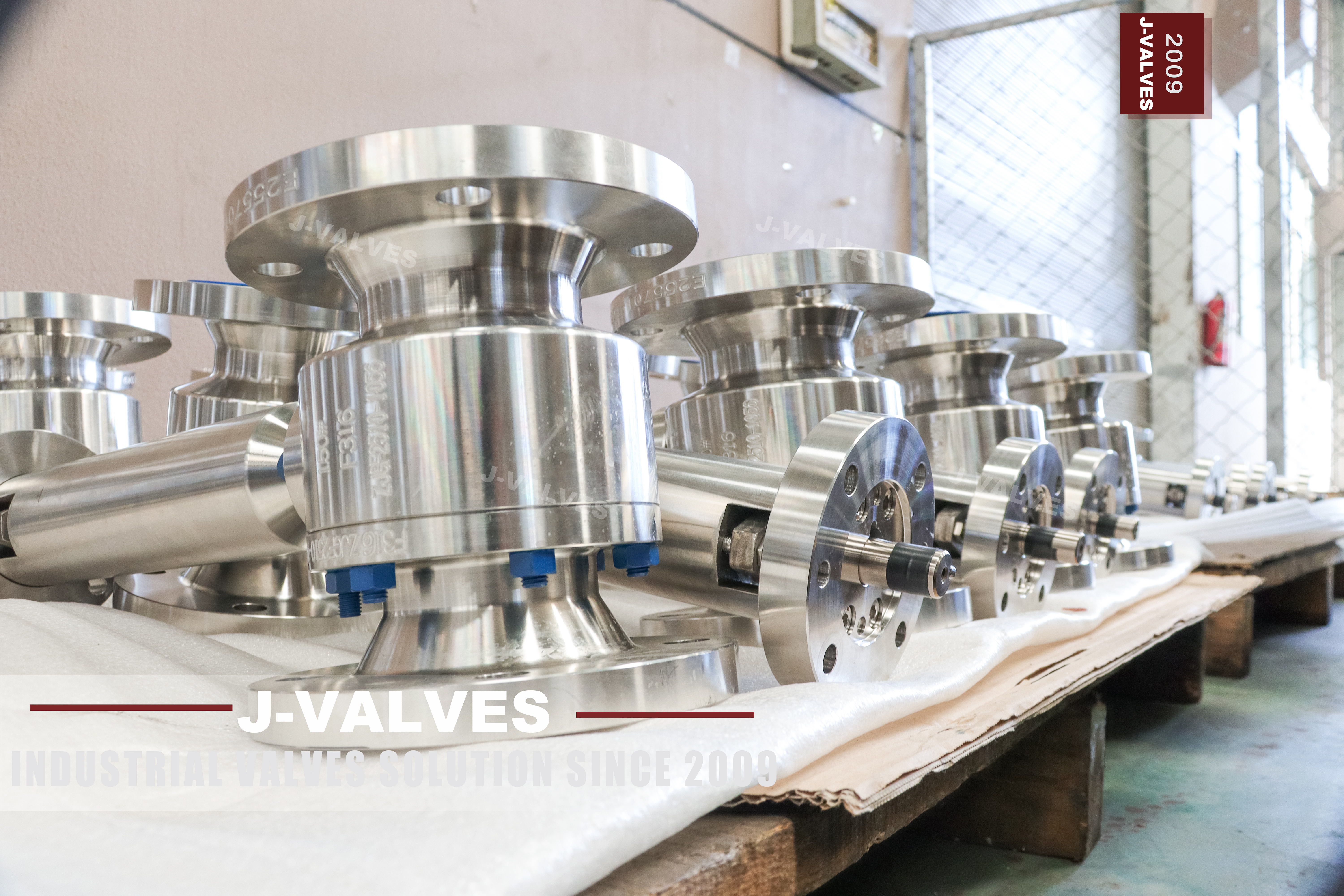
Two sizes are written on this valve and only one of them fits the pipe. The DN80 end is the three inch raised face flange that bolts to the line; the DN50 figure is the bore through the ball and the seats. The valve therefore joins a three inch pipe and passes what a two inch pipe would pass. That is what reduced bore means, and it is the reason this body is lighter and its lever easier to turn than a full bore valve of the same flange size.
The Class 150 rating is the third number, and it does less work here than buyers expect. At this class the pressure is low enough that the wall thickness required by calculation falls below the minimum the standard allows, so the minimum governs. That single fact changes what the material choice can buy: a stronger alloy cannot make the shell thicker, because the shell was never sized by strength in the first place.
Design and Construction
The body is a forged stainless part split into two halves at one bolted joint. Forging is the normal route at three inches for a stainless body, and the reason is economic rather than metallurgical: a forging in this size range is cheaper to buy and easier to certify by heat than a casting, and the wrought structure has no porosity to find. The joint carries the seats and the ball, and it is the only place on the valve where the pressure boundary is made by bolts rather than by the material itself.
The ball floats. Line pressure pushes it downstream into the outlet seat and that contact is the seal; there is no trunnion and no bearing. With a DN50 bore at Class 150 the seat load stays modest, so the operating torque is low and a lever is enough. The reduced bore helps twice here: a smaller ball means a smaller seat ring, less friction and a shorter lever stroke, which is why reduced bore valves of this size are almost always hand operated.
Material Options
The body is forged stainless steel, and the page names F316. What that buys is resistance to chlorides and to mildly acidic media, which carbon steel does not have, and it is the reason this valve exists at a pressure class where a carbon steel body would be perfectly strong enough. What it does not buy is a thicker shell: at Class 150 the wall is at the standard minimum for the size, and the same minimum applies whatever alloy the body is made from.
Trim follows. The ball is F316 or a cast stainless grade with hard chrome plating, or a low carbon variant where welding or a corrosive medium asks for it; the stem is 316 or 17-4PH. Seats are PTFE, reinforced PTFE or PPL, and packing is flexible graphite or PTFE. The grade behind the code is settled by the nameplate and the mill certificate, not by this page, and the order should be written so that the certificate is what decides it.
| Component | Standard Material | Optional Upgrade | Service Notes |
|---|---|---|---|
| Body and side body | forged stainless steel, grade as stamped | the F316 code on the nameplate | two pieces, one bolted joint |
| Ball | stainless with hard chrome plating | low carbon stainless | ground, then plated |
| Stem | 316 stainless | 17-4PH | packing stays in the body |
| Seat | PTFE | reinforced PTFE or PPL | sets the service temperature |
| Packing | flexible graphite | PTFE | gland adjustable |
| Extension | 316 stainless, length to the drawing | carbon steel on request | not a pressure boundary |
| Ends | raised face, B16.5 Class 150 | EN 1092-1 PN 20 | DN80 pattern |
Technical Specifications
Flange drilling is to ASME B16.5 Class 150, and the page also offers EN 1092-1, which is a second drilling pattern rather than a second rating: the two are not interchangeable at the same nominal size and the order has to name one. Face to face is held to ASME B16.10 for a flanged valve of this size and class. Neither dimension is printed here as a number, because the number belongs to those tables, and a catalogue figure copied into a data sheet reads as if it had been measured on this valve.
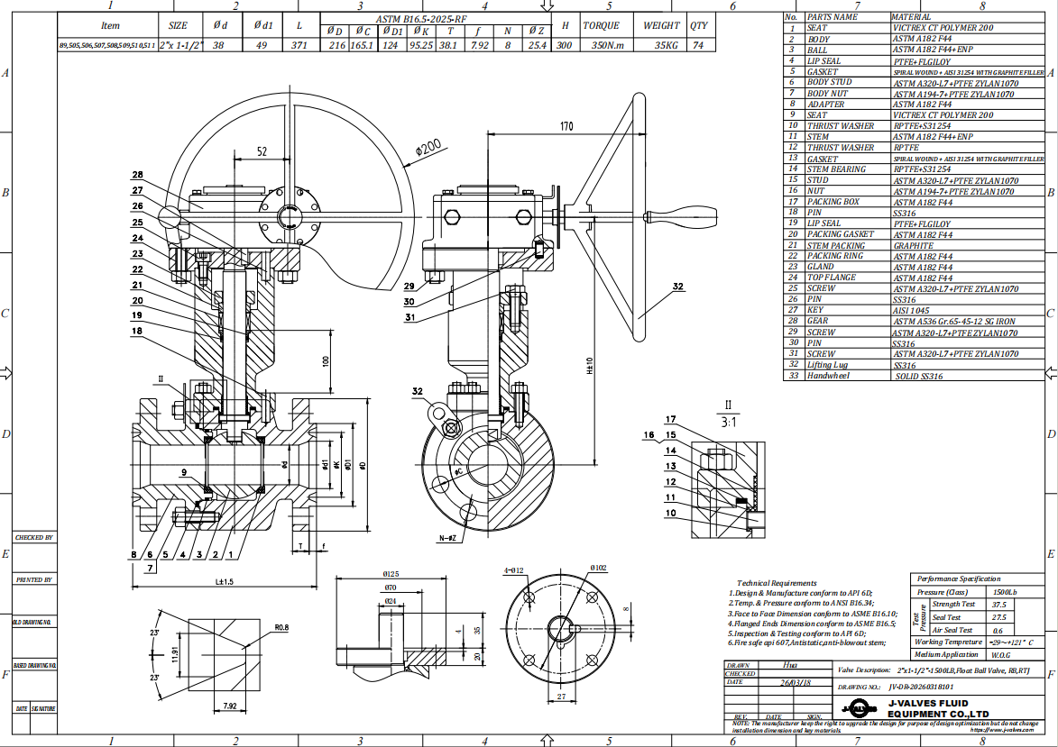
The bore is the dimension that decides flow. A DN50 passage in a DN80 body is the narrowest point in the run, so pressure drop is calculated on the bore and not on the flange, and the same is true of any cleaning pig or brush that has to pass. Anything not fixed by a standard, such as overall height with a particular stem extension, is dimensioned on the signed general arrangement drawing for the size and trim ordered.
| Item | Value |
|---|---|
| Nominal size | DN80x50 (3x2 inch, DN80 flanged ends and DN50 bore) |
| Pressure class | Class 150 (PN 20) |
| Body style | two piece, one bolted joint |
| Ball support | floating, no trunnion |
| Bore | reduced bore, DN50 |
| Body material | forged stainless steel, grade as stamped on the nameplate |
| Ball material | stainless with hard chrome plating, low carbon grade optional |
| Stem | 316 stainless, 17-4PH optional |
| Seat | PTFE, reinforced PTFE or PPL |
| Packing | flexible graphite or PTFE |
| Extended stem length | 200 mm to 1000 mm typical, set by the service |
| End connection | raised face, ASME B16.5 Class 150 or EN 1092-1 PN 20 |
| Face to face | dimension on the signed GA drawing, held to ASME B16.10 |
| Design standard | ASME B16.34 and API 608 |
| Test standard | API 598 shell and seat test |
| Test pressure | shell 1.5 times and seat 1.1 times the class rating |
| Wall thickness | at the standard minimum for the size and class, not set by alloy strength |
| Temperature range | minus 29 to plus 425 Celsius, metal temperature |
| Temperature limit | set by the seat compound, not by the body |
| Operation | lever with locking hole; gear, pneumatic or electric optional |
| Fire test | not claimed on this page, API 607 to be specified if required |
| Anti static device | not claimed on this page |
| Marking | size, class, body code, heat number |
| Documentation | EN 10204 3.1 on request |
| Weight | quoted with the drawing for the size and trim ordered |
| Country of manufacture | China |
Standards and Compliance
B16.34 does two jobs and they are regularly confused. It sets the minimum wall for a size and class, which at Class 150 is the governing number. It also publishes the pressure temperature rating for the material group, and that table is where the alloy earns its place: an austenitic group has its own curve, flatter at low temperature and falling faster at high temperature than carbon steel does. API 608 adds the quarter turn requirements and API 598 supplies the test numbers. Reading only the first job is how buyers conclude that a stainless body must be stronger.
The page does not claim a fire test for this valve, does not describe an anti static device and does not state an actuator mounting pattern. For a general purpose valve those three omissions are ordinary and they are not defects, but each one decides what the valve can be used for. A fire test of the API 607 type is a design qualification and has to be ordered by name; anti static continuity matters where charge can build in the medium; a mounting pad has to exist before an actuator can be bolted on later. None of the three can be added at site.
| Requirement | Standard | What J-VALVES Supplies |
|---|---|---|
| Pressure boundary | ASME B16.34 | minimum wall for the size and class, plus the rating for the alloy group |
| Ball valve design | API 608 | the quarter turn requirements for this product |
| Shell and seat test | API 598 | 1.5 times the rating for the shell, 1.1 times for the seat |
| Flange drilling | ASME B16.5 Class 150 | DN80 raised face pattern, EN 1092-1 on request |
| Face to face | ASME B16.10 | flanged valve length for the size and class |
| Marking | API 608 and the order | size, class, body code, heat number |
| Fire test | not claimed on this page | API 607 named on the order if required |
| Documentation | EN 10204 3.1 | issued against the heat number on request |
Manufacturing Process
Forged blanks are machined in one setup where the shape allows, so the bore, both seat pockets and the flange face stay concentric. On a reduced bore body there is a second concentricity to hold: the transition from the DN80 flange bore down to the DN50 passage has to be centred on the same axis, or the seat ring will sit with uneven crush and leak at low pressure. That transition is machined rather than cast, which is one of the quieter advantages of a forged body.
Closing the body is the step that decides whether the seats survive their first year. If one side is pulled down fully before the other, the ball is pushed off centre and the seats end up carrying unequal load, which reads later as a valve that leaks in one direction only. The extension is fitted after the body is closed, with the coupling aligned so the stem turns freely. Each unit is cycled and pressure tested before marking, and the marking ties the valve to its heat number.

Quality Control and Testing
On a reduced bore body the seat test is the interesting one, because the seat ring is sized by the DN50 passage rather than by the DN80 flange, and a small ring has less margin against a damaged face. What the test asks is whether that face is flat enough to hold: a ring that is slightly off shows a weep that grows with pressure rather than a clean break. The shell test covers the body and the joint, the seat test covers the trim, and both are read at the bench with the valve cycled between directions.
It is not proven to be the alloy that was ordered. That question is answered by the mill certificate behind the 3.1 documentation and, where the buyer asks for it, by positive material identification on the finished body. On a stainless valve this matters more than on a carbon steel one, because the difference between two austenitic grades is invisible to the eye and to a pressure gauge, and the medium that motivated the upgrade is exactly the one that will find the mistake.
| Step | What Is Checked | Standard or Acceptance |
|---|---|---|
| Incoming forgings | grade, heat number, wall thickness | certificate against the stamped code |
| Machining | bore, reduced bore transition, seat pocket depth | in process gauging against the drawing |
| Ball | roundness and plating thickness | sampled before assembly |
| Assembly | seat crush both sides, stem torque | controlled torque on the body joint |
| Shell test | no leakage through the body wall | API 598 at 1.5 times the rating |
| Seat test | no visible leakage, both directions | API 598 at 1.1 times the rating |
| Extension | runout, coupling alignment | checked against the drawing before packing |

Applications and Industry Service
This valve is bought where the medium needs stainless and the pipe is three inches. That covers chloride bearing water, light acids, food and pharmaceutical utilities, and the cooling or process branches where a carbon steel body would pit within a few years. The extended stem is a separate decision from the material: it puts the lever outside insulation, outside a cold box wall or above a pit cover while the body stays where the pipe is.
It is the wrong valve in three situations. A medium that needs a fully resistant alloy will not be saved by F316, which is resistant rather than immune. A line that must be pigged cannot use a reduced bore body at all, because the DN50 passage blocks the tool. And a service above the seat compound ceiling will deform the seat long before the body is in trouble, since the printed range describes the metal and the seat has its own much lower limit.

Installation, Operation and Maintenance
Mount with the stem vertical or horizontal, never upside down, and leave room to swing the lever through ninety degrees. On an extended stem valve the extension has to be plumb within the tolerance the drawing states, because a stem running out of line loads the gland on one side and wears the packing oval. Support the extension where the length is significant; it is not a pressure boundary, but it is a lever arm, and a hand leaning on it transfers that load to the packing.
Maintenance is seat replacement through the body joint, with the valve out of the line. Both seats are replaced as a pair, because a worn seat on one side will damage a new one on the other. Packing is adjusted at the gland and replaced when the gland runs out of travel. The lever should turn without a cheater bar; if it needs one, the seat has swollen or the cavity has scaled, and forcing it damages the stem before it frees anything.
How to Specify and Order
The order line needs six things: the size written as flange by bore, the class, the body alloy code as it will be stamped, the seat compound, the flange standard, and the extension length with its datum. The flange standard deserves its own place on that list, because ASME B16.5 and EN 1092-1 are different drillings at the same nominal size and a valve cannot satisfy both at once. If the grade is not settled, let the certificate settle it rather than writing a grade nobody has poured.
Before shipment the nameplate, the mill certificate and the general arrangement drawing should agree with each other. The nameplate carries size, class, body code and heat number. The certificate carries chemical and mechanical results for that heat. The drawing carries face to face, flange drilling, bore and extension length. When they disagree, either the valve is right and the paperwork is wrong or the reverse, and neither can be found at site without taking the line apart.
FAQ
Q: Why is the body wall not thicker when the material is upgraded?
A: Because at Class 150 the wall is not sized by the strength of the alloy. The pressure boundary standard sets a minimum wall for each size and class, and at this class the thickness calculated from pressure falls below that minimum, so the minimum governs. Moving from carbon steel to a stainless grade therefore changes what the body resists, not how thick it is. A thicker shell at the same bore means a higher class.
Q: What does DN80x50 mean, and which pipe does it fit?
A: It fits a three inch pipe and passes what a two inch pipe would pass. DN80 is the flanged end and DN50 is the bore through the ball and the seats, so the valve is a reduced bore design. Pressure drop is calculated on the DN50 passage rather than on the flange, and any pig or brush sent down the line will stop at the valve rather than pass through it.
Q: Is F316 the right choice for chloride service?
A: It is resistant to chlorides rather than immune to them, and the distinction matters at the concentration and temperature where pitting starts. F316 is a reasonable answer for mildly chloride bearing water at moderate temperature; it is not the answer for hot concentrated brine, where a higher alloy is needed. The grade code on the nameplate and the medium data in the enquiry are what the selection should rest on.
Q: How is the extended stem length specified?
A: By the insulation thickness or the pit depth plus the clearance the operator needs, measured from a stated datum on the valve. The catalogue range is a range and not an order line, so the length and the datum both have to appear on the purchase order and on the drawing. A valve built to a length with no datum is the most common cause of a unit arriving too short or too long.
Q: Does this valve hold a fire test?
A: No fire test is claimed for it here, and no anti static device is described. A soft seated quarter turn valve in hydrocarbon service is commonly required to hold an API 607 type test before acceptance, but that is a type test on the design and it has to be asked for by name. It is not covered by the routine shell and seat test to API 598.
Q: Which flange standard should be ordered?
A: One of them, not both. ASME B16.5 Class 150 and EN 1092-1 PN 20 are different drillings at the same nominal size, so a valve cannot be machined to satisfy both. The pipe class on the project drawing decides which one applies, and the order should name it explicitly, because a valve drilled to the other standard will not bolt up at site however correct its rating is.


Hot Products


News
Ball Valves in Geothermal Brine: Silica Scale, Chloride Cracking And The Cooling Trap
Why geothermal brine destroys ball valves: retrograde silica scale, calcite at the flash point, chloride cracking above 60 C and the 250 C seat limit.
Read More
Ball Valve Face To Face Dimensions: Why A Correctly Ordered Replacement Still Does Not Fit
A 6 inch Class 150 ball valve can be 267 or 305 mm face to face and both are compliant. How B16.10, EN 558 and flange drilling decide whether it fits.
Read More
Ball Valve Stem Key And Keyway: What Gives Way First, And What The Handle Cannot Tell You
Between the handle and the ball there are four fits. Which one shears, which one cracks, and how a few degrees of lost motion hides a valve that never seated.
Read More
Ball Valve Datasheet: Six Blocks That Decide Whether Two Quotes Are Comparable
A ball valve datasheet only works when six blocks are fixed: pressure basis, bore, temperature ceiling, test, end connection, operator. How each is written.
Read More