


CHINA J-VALVES Offers Various High-quality I ndustrial Ball Valves
J-VALVES, a distinguished professional ball valve manufacturer rooted in China, takes pride in its extensive product portfolio. Our offerings span a wide range, including trunnion-mounted ball valves, floating ball valves, high-temperature ball valves, high-pressure ball valves, metal-sealed ball valves, ultra-low temperature ball valves, DBB ball valves, Three-way And Four-way Ball Valve, and fully welded ball valves. Each product is a testament to our commitment to precision engineering and reliable performance. Meticulously crafted, they are designed to not only meet but exceed the most stringent industrial demands, ensuring stable operation even under extreme conditions. This enables us to provide our clients with high-value services and makes our valves widely sought-after in industries.
Product Category
Contact Us


-
J-VALVES-Q41F
-
J-VALVES
Overview of the J-VALVES DN80x50 150LB A105 Extended Stem Ball Valve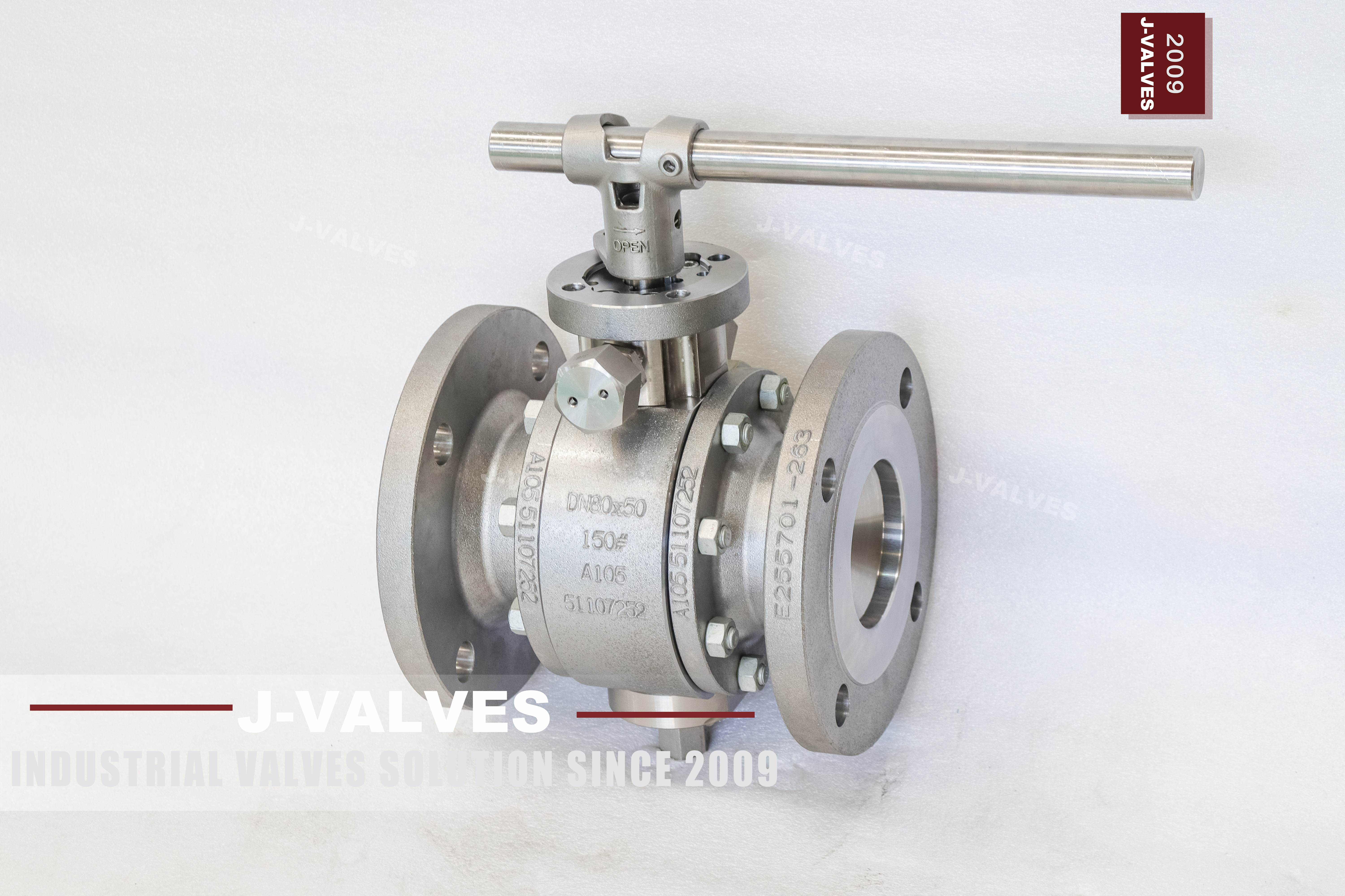
This is a reduced bore valve in a flanged body: DN80 flanges at both ends, DN50 bore through the ball, Class 150. The body is ASTM A105 forged carbon steel, normalised, and the stem runs up through an extension so that the lever or the actuator sits above the pipe rather than beside it. The valve is ordered as a size pair rather than a single size, and the extension is ordered as a length with a datum, so the two parts of the specification are read together. In the trade the pair is written 3x2 rather than DN80x50, which is why an order line quoting one form and a drawing quoting the other can describe the same valve.
The extension is not a cosmetic option. It exists because something has to be between the valve and the handle: a layer of insulation on a traced line, a depth of soil over a buried line, a concrete pit wall, or simply a pipe run that is too close to a walkway for a lever to swing. In every one of those cases the valve is the same and the extension is different.
That is why the length is the specification and the valve is the easy part. Two valves ordered as DN80x50 150LB A105 with a two hundred millimetre extension can arrive at the same site and only one of them will let the handle clear the insulation, because one was measured from the body centre and the other from the flange face. Getting that wrong is not a quality problem, it is a paperwork problem, and the cost is a second valve or a field modification to the insulation.
Design and Construction
The ball floats between two seat rings and the line pressure pushes it into the downstream seat, so the seal tightens as the pressure rises and only one seat is doing the work at a time. At DN50 bore and Class 150 the load is small, which is why the valve is still operated by a lever at the top of the extension rather than by a gearbox.
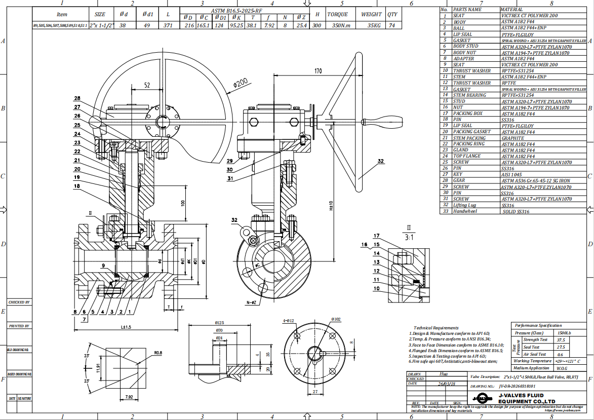
The stem is one machined part running from the ball slot to the top of the extension, supported by a tube that carries the operator and takes the side load a lever puts on it. The packing gland stays on the body where the stem leaves the pressure boundary; the extension above it is dry, and its only job is to put the handle where a person can reach it without disturbing the insulation.
The body opens at one bolted joint on the flange side, and the ball and both seat rings come out through that end. That is one pressure boundary to maintain rather than two, and it is the arrangement that suits a valve which is opened for cleaning rather than for a trim change. The upstream seat is reached from inside the centre section once the ball is out.
A reduced bore is written as a size pair because the flange size and the bore are different numbers. DN80x50 means DN80 flanges and a DN50 passage, so the valve drops into an eighty millimetre line and throttles the bore, not the pipe. It is a deliberate choice: it cuts the ball, the seat and the torque, and it is not a way of joining an eighty millimetre line to a fifty millimetre one.
Material Options
A105 is the body grade: forged carbon steel, normalised to refine the grain, with a rating band from minus 29 to plus 425 degrees Celsius. It is the right default for water, oil, gas and steam condensate, and it costs less than stainless at a size where the body is not the expensive part. A350 LF2 is the low temperature alternative where the line runs below minus 29 degrees.
The trim is carbon steel with a hard surface. Ball in A105 with hard chrome plating, or in 304 or 316 where the medium is corrosive; stem in 410 or 420 stainless, or 17-4PH where the extension is long enough that torsional stiffness matters. Seat in PTFE as standard, RPTFE or PPL where the line runs hotter, and the packing in PTFE or flexible graphite to match.
| Component | Standard Material | Optional Upgrade | Service Notes |
|---|---|---|---|
| Body and end piece | ASTM A105 forged carbon steel, normalised | A350 LF2 | one bolted body joint |
| Ball | A105 with hard chrome plating | 304, 316 | reduced bore, lapped sealing face |
| Stem | 410 or 420 stainless steel | 17-4PH for long extensions | one piece, straightened and checked for runout |
| Extension tube | A105 or stainless steel | length per drawing | dry above the gland, carries the operator |
| Seat ring | PTFE or RPTFE | PPL | sets the temperature limit |
| Body gasket | Graphite spiral wound | PTFE envelope | new gasket at every joint opening |
| Stem packing | PTFE V-ring | Flexible graphite | compressed at the body gland, not at the top |
| Body bolts | ASTM A193 B7 with A194 2H nuts | B8M with 8M nuts | one joint, cross pattern |
| Operator | Lever at the top of the extension | Worm gear, pneumatic, electric | mounting pad machined at the top |
Technical Specifications
The envelope is DN80x50 reduced bore, Class 150, body in normalised A105, raised face flanges, face to face to ASME B16.10, and pressure testing to API 598. The extension is a separate dimension on the drawing, measured from a stated datum to the top of the mounting pad or the centre of the lever, and it is confirmed before the stem is cut. Because the extension is made to the order, the drawing is issued for approval before the stem is cut, and the approved revision is the one that ships.
Three things have to be settled before the valve is built. The extension length and its datum, the flange standard, because ASME B16.5 and EN 1092-1 both exist at this size and do not share a bolt circle, and the seat compound against the line temperature. None of them can be corrected at the site without changing parts. A fourth point, often forgotten, is access for the operator: a lever that clears the insulation but cannot be reached from the platform is still the wrong length.
| Item | Value |
|---|---|
| Nominal size | DN80 x DN50 (3 x 2 inch), reduced bore |
| Pressure class | Class 150 (PN20) |
| Body construction | forged body, one bolted joint |
| Ball support | floating, no trunnion |
| Body material | ASTM A105 forged carbon steel, normalised |
| Body option | A350 LF2 for low temperature |
| Material group | ASME B16.34 group 1.1 carbon steel |
| Rating at 38 C | Class 150 = 19.6 bar |
| Temperature range | minus 29 to plus 425 C for A105 |
| Ball | A105 with hard chrome plating |
| Ball options | 304, 316 |
| Stem | 410 or 420 stainless steel |
| Stem option | 17-4PH |
| Seat | PTFE or RPTFE |
| Seat option | PPL |
| Packing | PTFE V-ring |
| Packing option | flexible graphite |
| Body gasket | graphite spiral wound |
| Body bolts | ASTM A193 B7 with A194 2H nuts |
| Bore | DN50 through DN80 ends |
| End connection | raised face flange, ASME B16.5 or EN 1092-1 as ordered |
| Face to face | ASME B16.10 |
| Stem extension | length per drawing, commonly 200 to 800 mm |
| Extension datum | stated on the drawing, body centre or flange face |
| Wall thickness | ASME B16.34 |
| Design standards | ASME B16.34 and API 608 |
| Pressure testing | API 598 shell and seat, both directions |
| Operator | lever at the top of the extension |
| Actuation options | worm gear, pneumatic, electric |
| Marking | size pair, class, A105 and heat number on the body |
| Documentation | EN 10204 3.1, test record, general arrangement drawing with the extension dimension |
Standards and Compliance
ASME B16.34 sets wall thickness and rating. A105 is carbon steel in material group 1.1, Class 150 corresponds to 19.6 bar at 38 degrees, and the group is rated to 425 degrees, above which graphitisation rather than wall strength is the limit. API 608 adds the ball valve requirements for the anti static path, the blowout proof stem and the nameplate content. Fire testing to API 607 is available where the project asks for it, and it is usually asked for on hydrocarbon service rather than on water.
The flanges are to ASME B16.5 or to EN 1092-1 depending on the market, and at DN80 the two standards give different bolt circles and different thicknesses even though both are called 150 or PN20. Face to face follows ASME B16.10 for the flanged pattern, and the extension does not change it, because the extension is above the valve, not in the pipe run. Where a valve is bought against a European specification, the EN flange is normally the right answer, and the ASME face to face still applies to the valve body itself.
| Requirement | Standard | What J-VALVES Supplies |
|---|---|---|
| Wall thickness and rating | ASME B16.34 | group 1.1 carbon steel, Class 150 = 19.6 bar at 38 C |
| Ball valve specifics | API 608 | anti static path, blowout proof stem, nameplate |
| Flanges | ASME B16.5 or EN 1092-1 | stated on the order; the bolt circles differ |
| Face to face | ASME B16.10 | flanged pattern for DN80 Class 150 |
| Pressure testing | API 598 | shell at 1.5 times, seat at 1.1 times, both directions |
| Material certificate | EN 10204 3.1 | certificate per heat |
Manufacturing Process
The body is forged, normalised and machined, with the seat pocket and the flange facing cut in one setting so the seat sits square to the ball axis. The stem is the part that needs the most care on an extended valve: it is turned from bar, heat treated, straightened and checked for runout over its full length, because a stem that is straight to a few hundredths over three hundred millimetres will bind in the gland at the top.
The extension tube is machined square at both ends and welded or threaded to the bonnet, and the assembly is checked for concentricity before the stem goes in. Assembly is seats and ball into the body, the joint closed on a new gasket, the stem fitted from the top through the extension, the packing compressed at the body gland, and the lever or the mounting pad fitted at the top.

Quality Control and Testing
The extension is measured, not assumed. The length is checked from the drawing datum to the top face, the stem runout is checked over its full length, and the assembly is turned through a quarter turn to confirm that the stem does not bind and that the ball reaches both seats without the lever fouling anything. A long stem that is straight on the bench can still bind once the packing is compressed.
Every valve is shell tested at one and a half times the rating and seat tested at one point one times, both to API 598, with the seat test run in both directions because a floating valve only seals on the downstream side. The breakaway torque is measured at the top of the extension, where the operator actually works, and not at the stem where it leaves the body.
| Step | What Is Checked | Standard or Acceptance |
|---|---|---|
| Incoming forging | chemical composition, mechanical properties | EN 10204 3.1 against A105 |
| Stem | runout over the full length, thread and key dimensions | drawing tolerance, checked on centres |
| Extension | length from the datum, squareness of both ends, concentricity | drawing dimension |
| Machining | seat pocket squareness, flange facing, joint face flatness | drawing tolerance |
| Assembly | quarter turn travel, no binding with the packing compressed | free operation by hand at the top |
| Shell test | body and joint at 1.5 times | API 598, no leak |
| Seat test | each seat in both directions at 1.1 times | API 598, no visible leak |
| Torque | breakaway torque measured at the top of the extension | recorded and issued with the drawing |

Applications and Industry Service
The duty is isolation on a line that is insulated, buried or in a pit: district heating and cooling distribution, insulated water and condensate lines, buried water mains with a valve box at the surface, tank farms and pump stations where the valve sits below grade, and cold rooms where the operator stands outside the insulated envelope. Most of these valves are installed once and left alone for years, so the specification is the only chance to get the height right, and the height is what the operator lives with.
It is not a solution for a hot line without insulation, where the extension only adds a bending load to the stem, and it is not a substitute for a proper extended bonnet on cryogenic service, where the requirement is to keep the packing warm rather than to put the handle within reach. Those are different products and should not be confused. If the line is above 425 degrees, or if the medium is cryogenic, this is the wrong product and a different construction should be quoted.

Installation, Operation and Maintenance
Set the valve so the extension is vertical unless the drawing says otherwise, support the pipe on both sides, and do not use the extension as a step or a handhold. On an insulated line the extension passes through the cladding with a sleeve, and the gap is sealed afterwards; sealing it before the valve is aligned is how insulation ends up inside the extension tube.
Operate a quarter turn, fully open or fully closed, and check the travel stops or the lever position rather than guessing from the handle angle. If the valve becomes stiff, look at the packing first, because a gland that has been over tightened to stop a weep is the usual cause on a long stem, and loosening it a fraction is often the whole repair.
How to Specify and Order
Write the size pair, the class, the body grade, the bore, the flange standard, the extension length with its datum, the seat and the operator. A typical line reads: DN80x50, Class 150, body A105 normalised, reduced bore, raised face flanges to ASME B16.5, extension 300 mm from the body centre to the mounting pad face, RPTFE seat, lever. If the height above grade matters more than the length, give that height and let the drawing work back to a length, which is the more reliable way to order.
Send the insulation thickness or the burial depth, a sketch of the installation if there is one, and the medium temperature. The first two decide the length, the third decides the seat. If the valve will be operated from a walkway, say so, because the height of the handle above finished grade is the number that matters, and it is not the same as the length of the extension.
FAQ
Q: How is the extension length measured?
A: From a datum stated on the drawing, and this is where most orders go wrong. The two common datums are the centre of the body and the flange face, and the difference between them is half the face to face length. A length given without a datum is not a specification. The other number that matters is the height of the handle above finished grade or above the insulation, which is not the same as the length of the extension.
Q: Why is the bore smaller than the pipe?
A: Because the size pair DN80x50 describes flanges and bore separately: DN80 flanges, DN50 passage. It is a reduced bore valve, not a reducer. The smaller bore cuts the ball diameter, the seat diameter and the operating torque, which is why a reduced bore valve is cheaper and easier to turn than a full bore one at the same flange size.
Q: Are the flanges ASME or EN?
A: Either, and the order has to say which. At DN80 Class 150 an ASME B16.5 flange and an EN 1092-1 PN20 flange do not share a bolt circle or a thickness, even though both are described as 150 or PN20 in conversation. A valve drilled to the wrong standard will not bolt to the pipe, and redrilling a flange is not something to plan for on site.
Q: Does the extension change the pressure or temperature rating?
A: No. The pressure boundary is still the body and the gland at the bottom of the extension; the extension above the gland is dry and carries no pressure. What the extension does change is the torsional stiffness of the stem and the bending load a lever puts on it, which is why a long extension gets a larger stem and a support tube rather than a longer version of the same one.
Q: Can it be actuated at the top?
A: Yes, and that is often the reason for the extension: the actuator sits above the insulation or above grade instead of inside it. The mounting pad is machined at the top of the extension, the stem top is cut for the drive, and the support tube is sized for the weight and the torque of the actuator rather than for a lever.
Q: What is the temperature limit?
A: Minus 29 to plus 425 degrees Celsius for the A105 body, and lower for the seat: PTFE to about 150 degrees, RPTFE to about 180, PPL to about 280. Above 425 degrees the answer is not a thicker body but a different grade, because carbon steel graphitises rather than simply losing strength.


Hot Products


News
Ball Valves in Geothermal Brine: Silica Scale, Chloride Cracking And The Cooling Trap
Why geothermal brine destroys ball valves: retrograde silica scale, calcite at the flash point, chloride cracking above 60 C and the 250 C seat limit.
Read More
Ball Valve Face To Face Dimensions: Why A Correctly Ordered Replacement Still Does Not Fit
A 6 inch Class 150 ball valve can be 267 or 305 mm face to face and both are compliant. How B16.10, EN 558 and flange drilling decide whether it fits.
Read More
Ball Valve Stem Key And Keyway: What Gives Way First, And What The Handle Cannot Tell You
Between the handle and the ball there are four fits. Which one shears, which one cracks, and how a few degrees of lost motion hides a valve that never seated.
Read More
Ball Valve Datasheet: Six Blocks That Decide Whether Two Quotes Are Comparable
A ball valve datasheet only works when six blocks are fixed: pressure basis, bore, temperature ceiling, test, end connection, operator. How each is written.
Read More