


CHINA J-VALVES Offers Various High-quality I ndustrial Ball Valves
J-VALVES, a distinguished professional ball valve manufacturer rooted in China, takes pride in its extensive product portfolio. Our offerings span a wide range, including trunnion-mounted ball valves, floating ball valves, high-temperature ball valves, high-pressure ball valves, metal-sealed ball valves, ultra-low temperature ball valves, DBB ball valves, Three-way And Four-way Ball Valve, and fully welded ball valves. Each product is a testament to our commitment to precision engineering and reliable performance. Meticulously crafted, they are designed to not only meet but exceed the most stringent industrial demands, ensuring stable operation even under extreme conditions. This enables us to provide our clients with high-value services and makes our valves widely sought-after in industries.
Product Category
Contact Us


-
J-VALVES-Q41F
-
J-VALVES
Overview of the J-VALVES 6 Inch Class 300 WCB Floating Ball Valve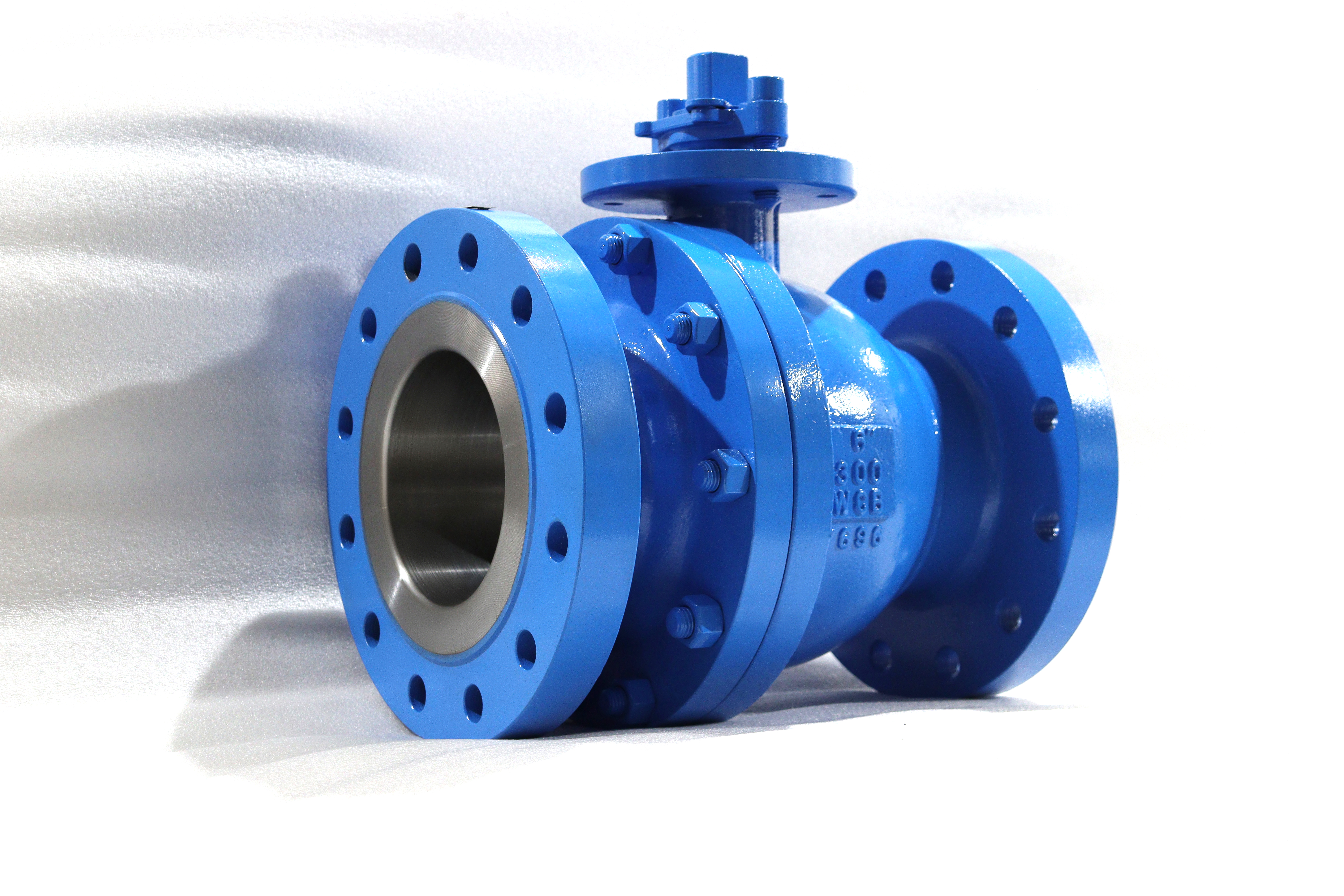
This is a six inch, Class 300, two piece floating ball valve with a cast WCB carbon steel body. DN150 is the nominal size, the ends are flanged to ASME B16.5 raised face, the face to face length follows ASME B16.10, the standard operator is a lever with a locking device, and the test is to API 598. The ball is not carried on trunnions; it sits between the two seats and the line pressure pushes it downstream onto the seat ring.
Six inch is worth a page of its own because it sits close to the practical upper limit of the floating design. Everything that makes a floating valve cheap and simple also makes it harder as the bore grows: the pressure acts on a larger ball area, the seat load rises with it, and the torque needed to break the valve away after a long closed period rises faster than a hand can comfortably supply. At two inch that is irrelevant. At six inch it is the first question a buyer should ask.
Design and Construction
In a floating design the ball is trapped between two seat rings and has a small amount of travel. When the line is pressurised, the pressure acting on the upstream half of the ball pushes the whole ball downstream until it seats. The seal is therefore produced by the line pressure itself, which is why a floating valve seals better as the pressure rises and why it can be difficult to turn at the same time: the same force that seals it also presses it into the seat.
The two piece body opens at one end cap, so the ball and the downstream seat come out from that side. At DN150 the end cap is still a part one person can handle, which is the practical difference against a larger valve where the end cap needs a sling. The stem enters from the top through the gland, is retained against blowout, and drives the ball through a slot; the anti static path runs from the ball through the stem to the body.

Material Options
WCB is the body material on this page and the one shown in the photograph: cast carbon steel, suitable for water, oil and gas at moderate temperature and the cheapest sound choice at this size and class. A105 forged carbon steel is offered where a wrought body is preferred for higher strength, and A350 LF2 is the low temperature grade. Those are alternative body materials and not coatings, so the choice changes the certificate as well as the valve.
The trim is carbon steel with a protective coating. The ball is WCB or A105 with electroless nickel plating, which is the standard because it gives a hard, smooth surface that a PTFE seat can seal against without the ball corroding in storage. Hard chrome and a stainless overlay are available for more abrasive duty. The stem is A105 with ENP, 17-4PH, or a 420 stainless where a harder stem is wanted, and the seat is PTFE or RPTFE with PPL and PEEK above that.
| Component | Standard Material | Optional Upgrade | Service Notes |
|---|---|---|---|
| Body and end cap | ASTM A216 WCB cast carbon steel | A105 forged, A350 LF2 | WCB is the standard at this size and class |
| Ball | WCB or A105 with ENP | Hard chrome, stainless overlay | plating protects the ball in storage as well as in service |
| Stem | A105 with ENP | 17-4PH, 420 stainless | blowout proof, retained by the body |
| Seat ring | PTFE or RPTFE | PPL, PEEK, metal with cobalt alloy facing | seat compound sets the real temperature limit |
| Body gasket | PTFE or spiral wound | Graphite filled for higher temperature | replaced every time the end cap is opened |
| Stem packing | PTFE V-ring | Graphite for higher temperature | matched to the seat temperature |
| Anti static device | Spring loaded ball to stem to body | Not applicable | required by API 608 |
| Operator | Lever with locking device | Worm gear, pneumatic, electric | gear where measured torque needs it |
Technical Specifications
The envelope is six inch, Class 300 which is PN50, two piece cast body, flanged to ASME B16.5 raised face, face to face to ASME B16.10, lever operated with a locking device, and a test to API 598. Butt weld ends to ASME B16.25 are available as an alternative where the line is welded rather than flanged. The figures that ship are the ones confirmed on the drawing for the size and class ordered.
Two numbers decide whether this valve is the right choice. The first is the bore: a six inch floating valve is normally full port, so the bore matches the pipe and a pig will pass. The second is the breakaway torque, which is not a catalogue constant; it moves with the seat compound, the temperature and how long the valve has been closed. That is why the torque is measured on the assembled valve and issued with the drawing rather than quoted from a table.
| Item | Value |
|---|---|
| Nominal size | 6 inch (DN150) |
| Pressure rating | Class 300 (PN50) |
| Body construction | two piece, bolted end cap |
| Ball support | floating, no trunnion |
| Body material | ASTM A216 WCB cast carbon steel |
| Body options | A105 forged, A350 LF2 |
| Ball | WCB or A105 with electroless nickel plating |
| Ball options | hard chrome, stainless overlay |
| Stem | A105 with electroless nickel plating |
| Stem options | 17-4PH, 420 stainless |
| Seat | PTFE or RPTFE |
| Seat options | PPL, PEEK, metal with cobalt alloy facing |
| Bore | full port, DN150 |
| End connection | flanged raised face to ASME B16.5 |
| End option | butt weld to ASME B16.25 |
| Face to face | ASME B16.10 |
| Wall thickness | ASME B16.34 |
| Design standard | ASME B16.34 and API 608 |
| Pipeline documentation | API 6D on request |
| Pressure testing | API 598 shell and seat, both directions |
| Operator | lever with locking device as standard |
| Operator options | worm gear, pneumatic, electric |
| Anti static | spring loaded path from ball to stem to body |
| Stem retention | blowout proof, retained by the body |
| Body cavity | self relieving through the seat |
| Temperature basis | set by the seat compound and packing ordered |
| Torque | measured on the assembled valve, issued with the drawing |
| Mounting pad | available for actuation on request |
| Marking | size, class, WCB and heat number on the nameplate |
| Documentation | EN 10204 3.1, test record, general arrangement drawing |
Standards and Compliance
The valve is designed to ASME B16.34 for the wall and the rating, with API 608 covering the ball valve specifics: the anti static path, the blowout proof stem and the nameplate content. The flange is to ASME B16.5, the face to face length to ASME B16.10, the butt weld ends where ordered to ASME B16.25, and the pressure test to API 598. API 6D applies where the buyer wants the pipeline documentation set, which is a different and heavier package than a general purpose valve needs.
API 608 is worth reading if the valve is going into a line where a third party inspects. It requires the stem to be retained so that it cannot be blown out, requires an electrical path from the ball to the body so that static cannot accumulate across the seat, and requires the nameplate to carry the rating and the material. A valve that lacks any of those is not a compliant ball valve however well it seals on the bench.
| Requirement | Standard | What J-VALVES Supplies |
|---|---|---|
| Wall thickness and rating | ASME B16.34 | wall calculation for DN150 Class 300 |
| Ball valve specifics | API 608 | anti static path, blowout proof stem, nameplate content |
| Flange dimensions and facing | ASME B16.5 | raised face as standard, ring joint on request |
| Face to face length | ASME B16.10 | length confirmed on the drawing |
| Butt weld ends where ordered | ASME B16.25 | end preparation drawing |
| Pressure testing | API 598 | shell at 1.5 times, seat at 1.1 times, both directions |
| Pipeline documentation where requested | API 6D | design document and test record package |
| Material certificate | EN 10204 3.1 | certificate per heat number |
Manufacturing Process
The body and the end cap are cast in WCB, then machined. The joint face and the seat pocket are machined in the same setting so that the seat ring sits square to the ball, and the flange face is turned to the ASME B16.5 profile. The ball is machined, ground, polished and then plated; the plating thickness and adhesion are checked because a patchy nickel layer is where a carbon steel ball starts to corrode in a damp warehouse.
Assembly is straightforward: seats into the body and the end cap, ball between them, end cap closed on a gasket, stem in from the top with the packing compressed to a set load, then the lever and the locking plate. The assembled valve is torqued and the figure recorded, and the lever is checked for full quarter turn travel with the locking device engaging at both ends.

Quality Control and Testing
Each valve is shell tested at one and a half times the rating and seat tested at one point one times in both directions to API 598. The seat test is done in both directions because a floating ball seals on the downstream seat only, so the upstream seat is proven on reverse flow; a valve tested one way can pass and still leak when the line is back pressured from the other side.
The rest of the record is dimensional and functional. The flange is gauged to ASME B16.5, the face to face length to ASME B16.10, the bore checked for full port, the plating checked for thickness, and the lever checked for travel and for the locking device. The torque is measured last, on the assembled valve, and it is the number that tells the buyer whether this size is still comfortable as a floating design or whether the duty has moved into trunnion territory.
| Step | What Is Checked | Standard or Acceptance |
|---|---|---|
| Incoming casting | heat number and chemical composition | EN 10204 3.1 against A216 WCB |
| Machining | seat pocket squareness to the ball axis, joint face flatness | drawing tolerance, checked on a surface plate |
| Ball plating | thickness and adhesion of the nickel layer | no blistering, thickness within the drawing range |
| Flange gauge | outside diameter, bolt circle, bolt hole diameter, facing | ASME B16.5 Class 300, gauged |
| Face to face | end to end length of the assembled valve | ASME B16.10, recorded |
| Shell test | body and the end cap joint at 1.5 times | API 598, no leak |
| Seat test | each seat in both directions at 1.1 times | API 598, no visible leak |
| Torque | breakaway and running torque on the assembled valve | recorded and issued with the drawing |
| Lever and lock | quarter turn travel and locking device at both ends | engages open and closed, no fouling |

Applications and Industry Service
The duty is isolation on water, oil and gas lines at plant and utility scale: cooling water headers, process water, fuel and lube lines, compressed air and inert gas, and general plant piping where a carbon steel body is acceptable. It is a general purpose valve rather than a pipeline valve, and it is priced and built accordingly. In most of those systems the valve is bought in a batch against a plant standard rather than as a one off, which is why the locking lever and the standard face to face length matter more than any single performance figure.
It suits a line that is operated occasionally rather than cycled constantly. Where a six inch valve is opened and closed every shift, the seat and the ball take far more wear than the catalogue life suggests, and a trunnion valve with a gear, or a different valve type altogether, is the better answer. Where the valve sits open for months and is closed for maintenance, this is exactly the right product and there is no reason to pay for a trunnion.

Installation, Operation and Maintenance
Fit the valve with the stem up or horizontal, check the gasket against both flange faces, and tighten the studs in a cross pattern. Leave the lever free to swing and make sure the locking device can engage in both the open and the closed position, because a valve that can only be locked open is not providing the isolation the procedure assumes. On a line that will be flushed, open the valve fully before flushing rather than using it as a throttle.
Operate the valve fully open or fully closed. A floating ball left part open puts the seat edge into the flow at high velocity and erodes it, and the erosion is not visible until the valve will not seal. If the lever becomes stiff, do not fit a longer lever or a cheater bar: on a six inch valve that usually means a deposit on the seat or a swollen elastomer, and more force damages the stem instead of solving the problem.
How to Specify and Order
State size, class, body grade, ball and seat trim, end type, face to face standard and operator. A typical line reads: six inch, Class 300, WCB body, ball WCB with ENP, RPTFE seat, raised face to ASME B16.5, face to face to ASME B16.10, lever with locking device. If the line is welded, ask for butt weld ends to ASME B16.25 instead, and say so early because the end preparation changes the machining.
Send the fluid, the design pressure and temperature, and how often the valve will be operated. The last one matters more than buyers expect: a valve cycled daily needs a different seat and often a different design from a valve cycled twice a year, and a six inch floating valve that is cycled constantly is the case where a trunnion valve usually turns out to be the cheaper answer over its life.
FAQ
Q: Is six inch too large for a floating ball valve?
A: It is at the upper end but still inside it at Class 300. The floating design is limited by the seat load growing with the pressure and the bore area, and at six inch that load is manageable with a lever or a small gear. Above this size and class the torque and the seat wear move the duty into trunnion territory, which is why the same catalogue usually changes design around this point.
Q: When should I choose a trunnion valve instead?
A: When the valve is large, when the class is high, or when it is cycled often. A trunnion carries the pressure load on bearings so the seat load is set by springs rather than by the line, which keeps the torque low and the seat alive. A floating valve is cheaper and simpler and is the right answer while the load stays small, which at Class 300 means up to about this size.
Q: Why is the torque measured rather than quoted?
A: Because it is not a constant. Breakaway torque moves with the seat compound, the temperature and how long the valve has been closed, and a catalogue figure for the size can be wrong by a factor that matters when an actuator or a gear is being selected. The figure on the drawing comes from the assembled valve, so it reflects the seats that were actually fitted.
Q: What does the locking device do?
A: It holds the lever in the open or the closed position so that the valve cannot be moved by vibration, by a passer-by or by the pressure pulse in the line. On an isolation valve that is part of a permit to work, being able to lock it closed is often a requirement rather than a convenience, so the locking device is standard on this valve and engages at both ends of travel.
Q: Can the valve be actuated?
A: Yes, with a mounting pad for a pneumatic or electric actuator and a stem that accepts the drive. That is ordered as a build rather than added later, because the pad and the stem top have to be machined for it. On a six inch valve the actuator is usually sized on the measured torque, which is why the torque record matters for more than the lever.
Q: Which seat should I order?
A: RPTFE is the standard for water, oil and gas at normal temperature. PPL and PEEK raise the temperature limit, and a metal seat with a cobalt alloy facing is available where the process rules out a polymer. The seat and the packing have to be chosen together, because a high temperature seat with standard packing is only as good as the packing.


Hot Products


News
Ball Valves in Geothermal Brine: Silica Scale, Chloride Cracking And The Cooling Trap
Why geothermal brine destroys ball valves: retrograde silica scale, calcite at the flash point, chloride cracking above 60 C and the 250 C seat limit.
Read More
Ball Valve Face To Face Dimensions: Why A Correctly Ordered Replacement Still Does Not Fit
A 6 inch Class 150 ball valve can be 267 or 305 mm face to face and both are compliant. How B16.10, EN 558 and flange drilling decide whether it fits.
Read More
Ball Valve Stem Key And Keyway: What Gives Way First, And What The Handle Cannot Tell You
Between the handle and the ball there are four fits. Which one shears, which one cracks, and how a few degrees of lost motion hides a valve that never seated.
Read More
Ball Valve Datasheet: Six Blocks That Decide Whether Two Quotes Are Comparable
A ball valve datasheet only works when six blocks are fixed: pressure basis, bore, temperature ceiling, test, end connection, operator. How each is written.
Read More