


CHINA J-VALVES Offers Various High-quality I ndustrial Ball Valves
J-VALVES, a distinguished professional ball valve manufacturer rooted in China, takes pride in its extensive product portfolio. Our offerings span a wide range, including trunnion-mounted ball valves, floating ball valves, high-temperature ball valves, high-pressure ball valves, metal-sealed ball valves, ultra-low temperature ball valves, DBB ball valves, Three-way And Four-way Ball Valve, and fully welded ball valves. Each product is a testament to our commitment to precision engineering and reliable performance. Meticulously crafted, they are designed to not only meet but exceed the most stringent industrial demands, ensuring stable operation even under extreme conditions. This enables us to provide our clients with high-value services and makes our valves widely sought-after in industries.
Product Category
Contact Us


-
J-VALVES-Q41F
-
J-VALVES
Overview of the J-VALVES 3 Inch 600LB Two Piece Floating Ball Valve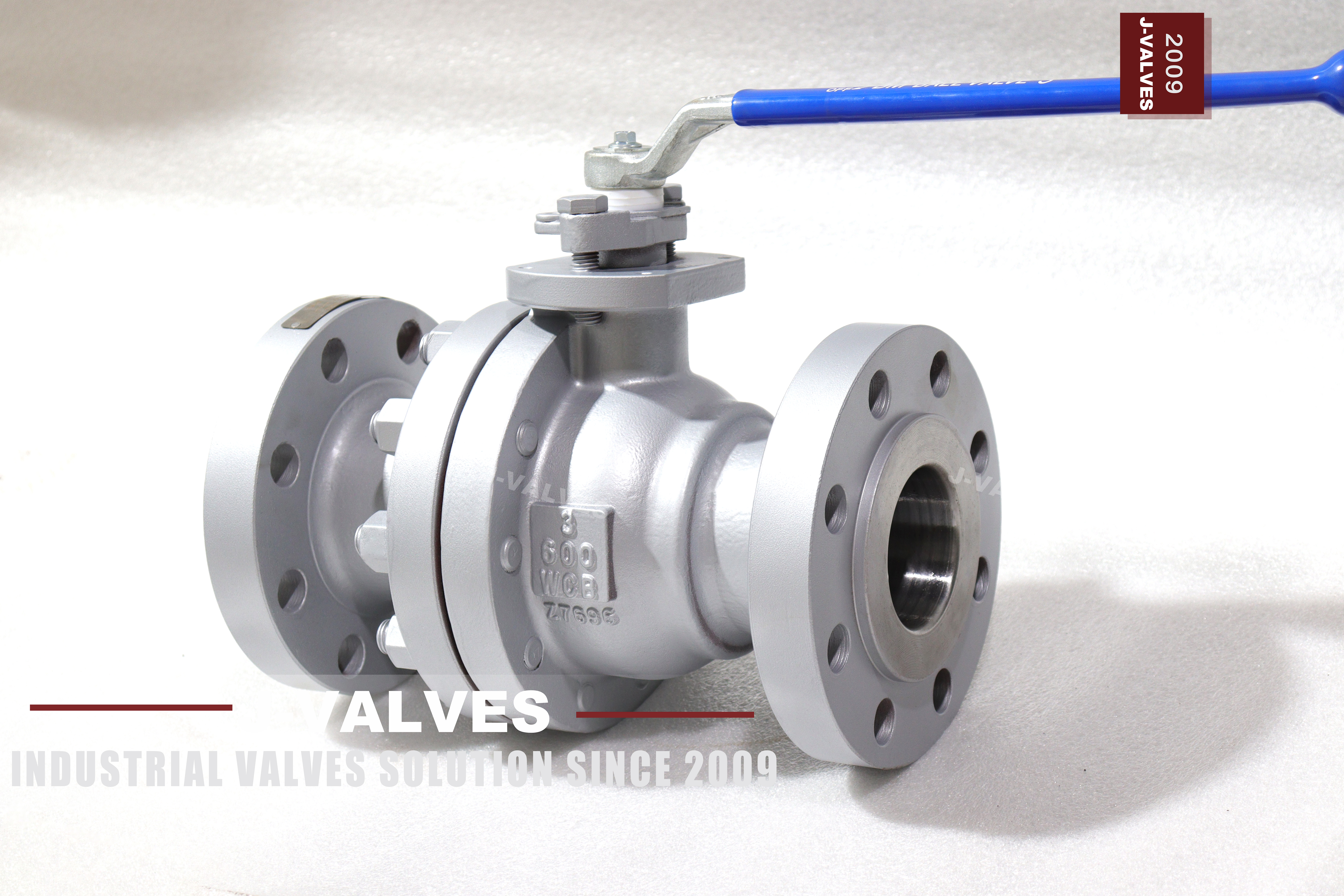
This is a three inch, Class 600, two piece flanged floating ball valve with a cast WCB body and a lever. It measures DN80 through the bore, it bolts to an ASME B16.5 Class 600 flange with eight studs, and its face to face length follows ASME B16.10. Everything that can be serviced on it is reached by taking one joint apart, and that single fact is what the rest of this page is about.
Buyers arrive at a page like this from two directions. One is a line list: the pipe is three inch, the class is 600, the valve has to be two piece and flanged, and the question is whether the face to face and the bolt pattern match what is already installed. The other is a leaking valve on a skid, where the question is whether the seat can be changed in place or whether the whole valve comes out. The dimensions and the joint detail answer both.
Design and Construction
The body is in two castings. The main body holds the stem, the gland, the packing and the upstream seat ring; the end cap holds the downstream seat ring and closes the bore. Four studs clamp the two together at DN80, and the joint face is a machined spigot and recess so the halves locate before the studs are tightened. Without that spigot the seats would have to be aligned by eye, and a ball pinched between two misaligned rings is the most common reason a rebuilt valve leaks.
The ball floats. Line pressure pushes it onto the downstream seat ring, the ring is pushed into its pocket, and the seal is made by that contact pressure rather than by a spring or a piston. The upstream seat is therefore unloaded while the valve is closed, which is why a floating valve seals tight in one direction and merely adequate in the other, and why the preferred flow direction should be marked on the line rather than assumed to be irrelevant.

Material Options
The body is WCB and the trim is a separate decision. A hard chrome plated A105N ball against a PTFE seat is the standard build for water and air; a stainless ball is specified when the medium carries solids that wear the chrome at the seat contact line; a PPL or metal seat is specified when the temperature passes the PTFE ceiling. None of these change the body or the joint, so the trim can be changed on a rebuild without touching the pressure boundary.
The parts that decide whether the valve can be rebuilt rather than replaced are the joint gasket and the seat rings. A spiral wound gasket with a graphite filler is single use: it seals once, and a gasket that has already been compressed will not seal again whatever torque is applied. The seat rings are the only other wear item in the flow path, and on a two piece valve they come out with the end cap rather than through a separate access cover.
| Component | Standard Material | Optional Upgrade | Service Notes |
|---|---|---|---|
| Main body | ASTM A216 WCB | Impact tested WCB for low temperature | Carries stem, packing and upstream seat |
| End cap | ASTM A216 WCB | Same heat as the main body where required | Holds the downstream seat, faces downstream |
| Ball | A105N or WCB, hard chrome | 304 or 316 stainless | Floats on line pressure, no trunnion |
| Stem | 410 or 420 stainless | 17-4PH | Blowout proof shoulder above the packing |
| Seat | PTFE | RPTFE, PPL, metal | Sets the temperature ceiling of the assembly |
| Packing | PTFE V rings | Flexible graphite | Adjustable without removing the body from the line |
| Joint gasket | Spiral wound, graphite filler | PTFE envelope for clean service | Single use, replaced on every opening |
| Anti static device | Spring loaded plunger, ball to body | None, it is a requirement not an option | Continuity measured on every valve |
| Bolting | A193 B7 with A194 2H | B7M for sour service | Eight studs at DN80 Class 600 |
| Operator | Lever with locking hole | Worm gear or actuator on the ISO 5211 pad | Quarter turn, 90 degree travel |
Technical Specifications
The numbers a piping engineer checks first are the face to face length, the bolt circle and the bore. At DN80 Class 600 the flange is an eight bolt pattern, which surprises buyers who are used to the four bolt pattern at Class 150 and 300 in the same size. The bore is a full DN80 through the ball, so the valve adds no restriction to the line and can be pigged in principle, although the seat pockets are not a pigging profile and a pig should not be sent through it.
The pressure class fixes four things at once: the wall thickness to ASME B16.34, the flange drilling to ASME B16.5, the shell test pressure at one and a half times the rating, and the actuator torque if one is fitted. Changing any one of them without changing the others is how a valve ends up with a Class 600 body and a Class 300 flange, which fits nothing and is discovered only at installation. Every figure in the table below is the figure the valve is tested against.
| Item | Value |
|---|---|
| Product type | Two piece flanged floating ball valve |
| Nominal size | 3 inch, DN80 |
| Pressure class | Class 600, PN100 in API 6D designation |
| Body material | ASTM A216 WCB cast carbon steel |
| Body construction | Two piece, one bolted joint, end cap downstream |
| Ball | A105N or WCB, hard chrome plated, solid |
| Ball option | 304 or 316 stainless, ENP or hard chrome |
| Stem | 410 or 420 stainless steel |
| Stem retention | Shoulder machined above the packing, blowout proof |
| Seat | PTFE, 150 C ceiling on the data sheet |
| Seat option | RPTFE 180 C, PPL 280 C, metal seat on request |
| Seat access | Through the body joint, end cap off, no top entry, in-line repair |
| Packing | PTFE V rings, adjustable at the gland |
| Body joint gasket | Spiral wound with graphite filler, replaced on opening |
| Bolting | A193 B7 studs, A194 2H nuts, cross pattern torque |
| End connection | Flanged raised face, ASME B16.5 Class 600 |
| Flange bolts at DN80 | Eight bolt pattern at Class 600 |
| Face to face | ASME B16.10, held on the drawing |
| Bore | Full port, DN80 through the ball |
| Design standard | ASME B16.34, API 608 |
| Anti static | Spring loaded contact, ball to body, measured per valve |
| Fire safe | API 607 with the seat compound supplied |
| Test standard | API 598, shell 1.5 times and seat 1.1 times |
| Temperature range | -29 to 425 C body, ceiling set by the seat |
| Operation | Lever, quarter turn, locking hole in the handle |
| Operation option | Worm gear, pneumatic or electric to ISO 5211 |
| Mounting pad | ISO 5211 pad on the neck for actuator retrofit |
| Marking | Size, class, material and heat number on the body |
| Traceability | EN 10204 3.1 certificate per heat |
| Spare parts | Seat pair and joint gasket are the first wear items |
Standards and Compliance
API 608 is the standard that actually governs this product, and it asks for three things that are easy to leave out. The first is a blowout proof stem, which on this valve is a shoulder machined above the packing so the stem cannot be pushed out by line pressure even with the gland released. The second is an anti static path from the ball to the body, because a dry PTFE seat insulates the ball and a static charge on a ball in a fuel line is an ignition source. The third is nameplate content, which has to carry size, class, material and the manufacturer.
ASME B16.34 supplies the wall and the pressure temperature rating, ASME B16.5 the flange, and ASME B16.10 the face to face length. API 598 governs the test, with a shell test at one and a half times the rating and a seat test at one and a time the rating in both directions. API 607 is the fire test and it is passed on the metal shoulder behind the seat and the graphite gasket in the joint, not on the PTFE, which is consumed. API 6D only applies when the line is a pipeline rather than plant piping.
| Requirement | Standard | What J-VALVES Supplies |
|---|---|---|
| Body wall and rating | ASME B16.34 | Cast wall tabulated for Class 600 in carbon steel |
| Valve design and marking | API 608 | Anti static path, blowout proof stem, nameplate content |
| Flange drilling | ASME B16.5 Class 600 | Eight bolt pattern at DN80, raised face |
| Face to face | ASME B16.10 | Length held on the signed drawing, not from a catalogue |
| Pressure test | API 598 | Shell 1.5 times and seat 1.1 times the rating, both seats |
| Fire test | API 607 | Certificate supplied against the seat compound ordered |
| Actuator interface | ISO 5211 | Pad on the neck, drive size stated on the drawing |
| Material certificate | EN 10204 3.1 | Heat number traced from the body casting |
| Pipeline option | API 6D | Documentation added where the line is a pipeline |
Manufacturing Process
Both castings come from the same pattern and are normalised before machining. They are then machined as a pair: the joint faces are cut first, the two halves are bolted together, and the bore and the seat pockets are cut through both at once. Machining them separately and relying on the spigot to align them works only if the spigot itself is concentric, and the tolerance stack that way is larger than the seat preload can absorb.
The flange is drilled last from the ASME B16.5 table for Class 600 at DN80, and the eight hole pattern is indexed off the centre line of the bore rather than off a cast lug. The stem bore is drilled and reamed in the same setting as the seat pockets so that the stem is square to the ball, because a stem that leans by half a degree puts the ball off its seat at one end of the travel and is read as a seat problem on the test bench.

Quality Control and Testing
Every valve gets a shell test with the joint assembled and a seat test in both directions, and the seat test is run twice because a two piece valve has two independent seat paths. The shell test is the one that finds a casting defect or a badly torqued joint, and it is run before painting so that a weep at the joint does not have to be found through a coating. The torque figure issued with the valve is measured at the rated pressure on the assembled valve, not taken from a table.
Two checks are specific to this design and are often skipped. The first is anti static continuity, measured from the ball to the body flange in ohms and recorded per valve. The second is the stem squareness check, done by measuring ball runout at both ends of the travel. A valve that passes the seat test cold and leaks after a month in service usually failed one of these two and was never measured for it.
| Step | What Is Checked | Standard or Acceptance |
|---|---|---|
| Chemistry | Carbon and manganese within the WCB range | Spectrographic analysis per heat |
| Casting | Porosity at the joint face and seat pockets | Visual and penetrant, radiography on request |
| Bolt circle | Eight bolt pattern against ASME B16.5 | Gauged, recorded per valve |
| Face to face | Length against the drawing | Measured with the gauge recorded on the sheet |
| Seat pocket | Depth and squareness to the bore | Checked from the same setting as the bore |
| Shell test | Body and joint under pressure | 1.5 times the rating, held to API 598 |
| Seat test | Both directions, both seats | 1.1 times the rating, no visible leakage |
| Anti static | Ball to body continuity | Measured in ohms on every valve |
| Torque | Breakaway torque at the rated pressure | Measured on the assembled valve, issued with the drawing |

Applications and Industry Service
The valve is used on plant water, cooling circuits, compressed air, fuel transfer and low pressure steam, in sizes where a lever is still practical and the line is not pigged. Its real advantage shows on a valve that is expected to be rebuilt rather than replaced: because the seats come out with the end cap and nothing above the body has to be disturbed, a seat change on an actuated valve leaves the actuator, its bracket and its wiring in place.
It is the wrong valve for chlorides, for acids, for anything above the seat ceiling, and for throttling duty. It is also the wrong valve where the line will be pigged, where double block and bleed is required, or where the valve has to fail closed on air or power failure without a spring return. Those are product class decisions, and no amount of trim selection fixes them.

Installation, Operation and Maintenance
The valve goes in with the end cap downstream so the joint sits on the low pressure side when the valve is closed. The eight studs are drawn up in a cross pattern in three stages to the torque on the drawing, because a WCB flange is stiff enough to distort a gasket if one stud is taken to full torque first. The valve is not a pipe support and should not be used to pull two pipe ends together, which is the most common cause of a joint that weeps at the first thermal cycle.
A seat change is a planned job: isolate, vent, drain, take out the studs, lift the end cap, and the downstream seat and the ball are accessible. The joint gasket is replaced as a matter of course and the seat rings are inspected for a worn contact band rather than for visible damage. The stem packing can be tightened at the gland in service, but replacing it needs the actuator off and is a workshop job on an actuated valve.
How to Specify and Order
An order needs size, class, body material, trim, flange facing and face to face standard; for this valve that is three inch, Class 600, WCB, PTFE seat, raised face, ASME B16.10. If the valve replaces an existing one, the installed face to face length and the bolt circle should be measured rather than assumed, because a valve that matches the class but not the length will not go into the gap that is already there.
Ask for the material certificate to EN 10204 3.1, the pressure test record, the anti static reading and the measured torque. Order a spare seat pair and a joint gasket with the valve: they are the two items that stop it working, they cost little, and on a two piece valve they are the difference between a rebuild and a replacement. Where an actuator will be fitted later, the ISO 5211 pad size and the drive should be recorded now rather than measured off the valve afterwards.
FAQ
Q: What is the face to face length of a 3 inch Class 600 ball valve?
A: It follows ASME B16.10 for the valve type and class, and it is held on the signed drawing rather than inferred from the size. If the valve replaces an existing one, measure the gap and the bolt circle in place: a valve that matches the class but not the length will not fit the space that is already there.
Q: How many bolts does a 3 inch Class 600 flange have?
A: Eight. At DN80 the Class 600 pattern is eight bolt, while the same size at Class 150 and 300 is four bolt. That change is the most common reason a buyer orders the right size and the wrong flange, so the bolt circle should be checked against ASME B16.5 rather than against the bolt count of the old valve.
Q: Can the seat be replaced without removing the valve from the line?
A: No. The seats are reached by taking the body joint apart, so the line has to be isolated, vented and drained first. What the two piece design does allow is a seat change without disturbing anything above the body, so an actuator, its bracket and its wiring stay in place while the end cap comes off.
Q: What does API 608 require on this valve?
A: Three things beyond the dimensions: a blowout proof stem, an anti static path from ball to body, and a nameplate carrying size, class, material and manufacturer. The stem on this valve is retained by a shoulder above the packing, and the anti static path is a spring loaded contact measured on every valve.
Q: Why does the valve seal better in one direction?
A: Because the ball floats. Line pressure pushes it onto the downstream seat, so the downstream seal is loaded by the medium and the upstream seat is unloaded. It is a bidirectional valve but not a symmetric one, and the preferred direction should be marked on the line when it is installed.
Q: Is a two piece valve cheaper to maintain than a three piece one?
A: It depends on the failure. A two piece valve needs only one joint opened and has one gasket to replace, so a seat change is quicker. A three piece valve lets the centre section come out completely, which is easier on a bench but adds two joints and two gaskets to the same job. For a valve that stays in the line, two piece is usually the cheaper maintenance path.


Hot Products


News
Ball Valves in Geothermal Brine: Silica Scale, Chloride Cracking And The Cooling Trap
Why geothermal brine destroys ball valves: retrograde silica scale, calcite at the flash point, chloride cracking above 60 C and the 250 C seat limit.
Read More
Ball Valve Face To Face Dimensions: Why A Correctly Ordered Replacement Still Does Not Fit
A 6 inch Class 150 ball valve can be 267 or 305 mm face to face and both are compliant. How B16.10, EN 558 and flange drilling decide whether it fits.
Read More
Ball Valve Stem Key And Keyway: What Gives Way First, And What The Handle Cannot Tell You
Between the handle and the ball there are four fits. Which one shears, which one cracks, and how a few degrees of lost motion hides a valve that never seated.
Read More
Ball Valve Datasheet: Six Blocks That Decide Whether Two Quotes Are Comparable
A ball valve datasheet only works when six blocks are fixed: pressure basis, bore, temperature ceiling, test, end connection, operator. How each is written.
Read More