


CHINA J-VALVES Offers Various High-quality I ndustrial Ball Valves
J-VALVES, a distinguished professional ball valve manufacturer rooted in China, takes pride in its extensive product portfolio. Our offerings span a wide range, including trunnion-mounted ball valves, floating ball valves, high-temperature ball valves, high-pressure ball valves, metal-sealed ball valves, ultra-low temperature ball valves, DBB ball valves, Three-way And Four-way Ball Valve, and fully welded ball valves. Each product is a testament to our commitment to precision engineering and reliable performance. Meticulously crafted, they are designed to not only meet but exceed the most stringent industrial demands, ensuring stable operation even under extreme conditions. This enables us to provide our clients with high-value services and makes our valves widely sought-after in industries.
Product Category
Contact Us


-
J-VALVES-Q641F
-
J-VALVES
Overview of the J-VALVES PN16 CF8 Pneumatic Two Piece Flange Floating Ball Valve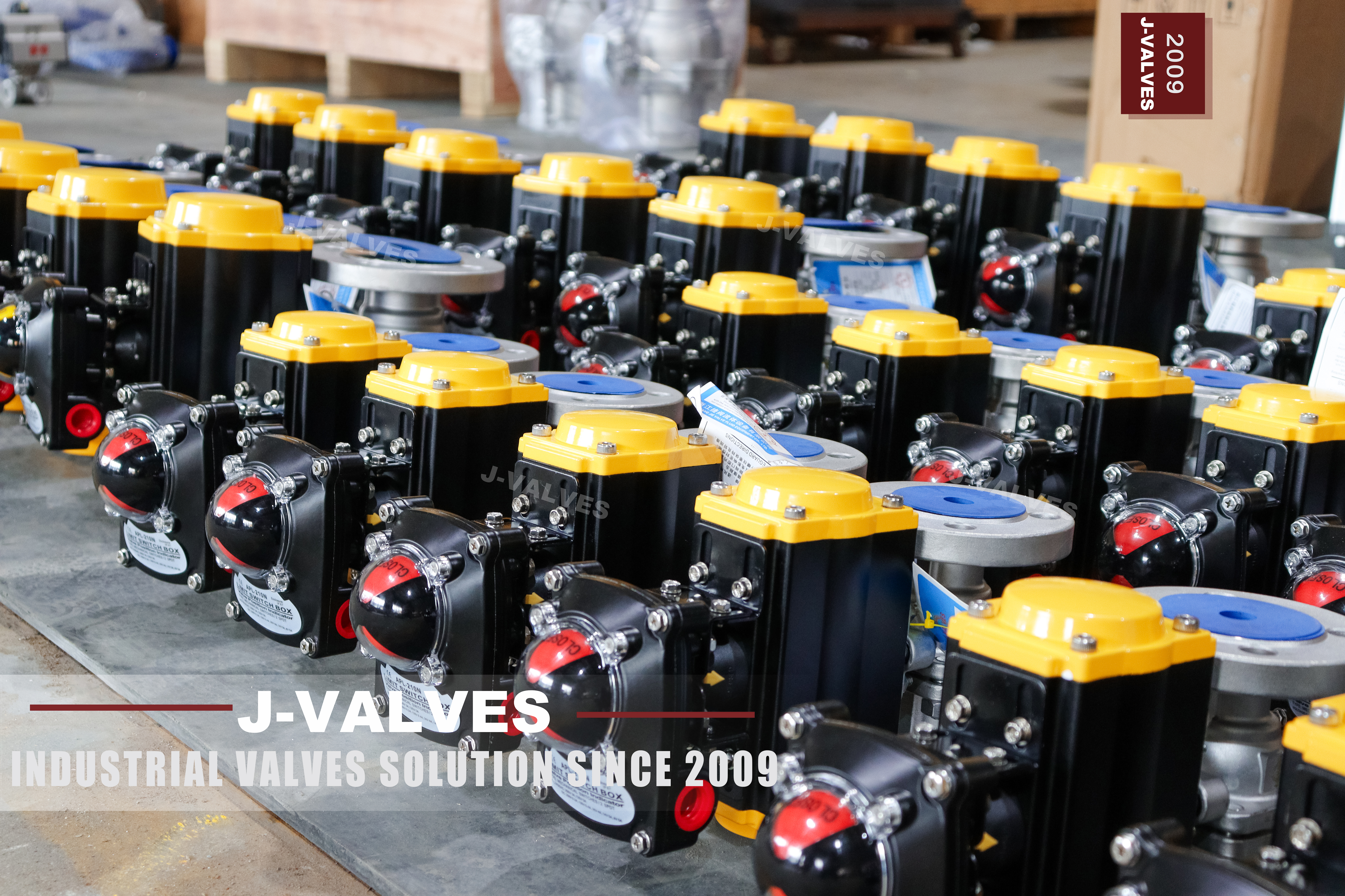
The valve in the photographs carries three marks cast into the body, and they are the whole specification: DN50 on both halves, PN16 beside it, and CF8 in the middle of the left face. Nothing else is stamped. A double acting pneumatic actuator sits on top through a bracket, a position indicator box sits on top of that, and both flanges are raised face with four bolt holes. The body is split once, on the downstream side of the ball, and that joint is closed by four bolts. The ball bore is a full port DN50, which means equal to the nominal size and not to the pipe inside diameter: wall thickness decides that, and the bore does not follow it.
This page is written around one uncomfortable fact: **four holes is the least useful evidence on the valve.** EN 1092-1 at DN50 PN16 has four holes, JIS 10K at 50A has four holes, and ASME B16.5 at NPS 2 Class 150 has four holes. Three pressure systems, one appearance, and a photograph cannot tell them apart; what separates them is bolt circle, bolt diameter and flange thickness, none of which can be read off a picture. The original listing solves this by not solving it, naming EN 1092-1 and GB/T 9113 in one line and ASME B16.5 or B16.47 in another — and B16.47 begins at NPS 26, so that line was written for another product and left in place.
The same three-URL problem that has run through this series lands here as well. The sister pages on this site describe the identical valve, with the identical six photographs, and each one declares a different standard family: this URL names EN 1092-1, one sister names JIS B2071 and B2002, another names ASME B16.34 and B16.10. That is not three variants of one valve. It is one valve with three sets of paperwork, and this page commits to the European set because the flange face in the photograph is the one the EN drawing describes. Where a project specifies JIS or ASME ends, the same body is drilled to that standard and the standard section changes with it, but the drilling and the paperwork have to move together.
Design and Construction
A two piece body splits once, and that split is the second pressure boundary in the valve. On this size the joint sits just downstream of the ball, so the right hand half is a end cap carrying one seat ring and the left hand half carries the ball, the stem bore and the other seat. Four bolts hold the two together, and between them sits the joint seal. Every leak path in a two piece valve either goes past a seat or through that joint, and the joint is the one that gets forgotten because it is not a wear part and nobody inspects it.
The ball is not carried on trunnions. It sits loose between two seat rings and line pressure decides where it rests: closed, pressure pushes the ball into the downstream seat and unloads the upstream one. The valve seals harder as pressure rises, and the torque the actuator must produce rises with the same load, because the ball has to slide against the pressure holding it shut. Because only the downstream ring carries load, there is no independent second seat and no drain port into the cavity between them, which is why this build cannot do double block and bleed.
The actuator interface is where this valve is actually specified, and the photographs show all of it. The valve top flange is drilled for both F05 and F07 under ISO 5211, so two actuator frame sizes bolt on without an adapter plate. A bracket lifts the actuator clear of the gland so the packing can be serviced with the actuator in place. The cylinder carries two G1/4 inch ports marked A and B, and four M5 holes on its top face for a solenoid or a switch box.
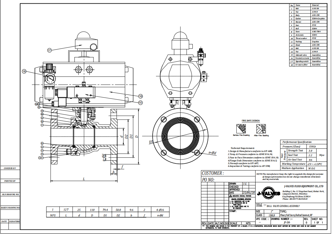
Material Options
CF8 is the cast equivalent of 304, and the word "equivalent" is doing real work. A351 CF8 and A240 304 are close in chemistry but they are different specifications with different mechanical property requirements, different test coupons and different acceptance rules. A casting is not rolled plate poured into a shape. What the certificate states is the grade that was cast, and that is the only statement about material this page will make.
The ball, the stem and the seats are inside the pressure boundary and no photograph shows them, so this page does not name a grade for any of the three. What can be said is what the parts must do. The ball is the sealing member and runs against the seats every cycle; the stem transmits the actuator torque and is the one part that must never corrode through, because it passes out of the body; the seats set the temperature limit of the assembled valve, not the body. Grades for all three are declared on the EN 10204 3.1 certificate against the heat numbers.
CF8 draws a boundary that gets crossed more often than any other on a stainless valve. Chloride stress corrosion cracking is a real failure mode for 304 austenitic castings above roughly hand warm temperatures in concentrated chloride service, and it is not a corrosion rate problem that shows up as wall loss — it is a crack. Seawater, brine, hypochlorite dosing and some cooling tower circuits are CF8M territory at minimum, and duplex beyond that. Ordering CF8 because it is the cheaper stainless is how these valves fail.
Technical Specifications
PN16 is a nominal pressure designation under EN 1092-1 and it means 16 bar at 20 degrees Celsius, derated above that according to the material group of the body. It is not a temperature-pressure rating in the way an ASME class is, and it is not the same number as Class 150. Class 150 in B16.34 is a table lookup against material group and temperature, and for the austenitic group this body belongs to the tabulated value at 38 degrees sits above 16 bar. Writing an equal sign between the two is the single most common error on this kind of page.
The temperature range on the original listing gives two answers, minus 29 to plus 425 Celsius in the property block and minus 29 to plus 220 Celsius in the template block, and they are not a typo. The 425 figure is the upper limit for carbon steel group 1.1 in B16.34, and this body is not carbon steel. The 220 figure is the upper limit of an RPTFE seat. The body can take more than the seat can, so the valve is limited by the seat, and the property block on this page splits the two instead of picking one.
The pneumatic side is where the original listing stopped at a single sentence, and it is the part that decides whether the valve works. Air supply is 0.4 to 0.7 MPa, ports are G1/4 inch, the mounting is ISO 5211 F05 and F07, and the cylinder in the photographs is double acting: two end caps of equal depth, four tie rods running the length of the body, no spring housing. Torque, air consumption and stroking time are measured on the assembled unit, because all three move with seat compound, differential pressure and temperature.
| Item | Value |
|---|---|
| Nominal size | DN50, cast on both body halves |
| Pressure designation | PN16, 16 bar at 20 °C, EN 1092-1 |
| Body material | ASTM A351 CF8, cast marking visible on the body |
| End connection | Raised face flange, four bolt holes, EN 1092-1 |
| Body construction | Two piece, single joint downstream of the ball, four joint bolts |
| Bore | Full port, ball bore equal to DN50 |
| Actuator | Pneumatic, double acting, ISO 5211 F05 / F07 mounting |
| Air supply | 0.4 to 0.7 MPa |
| Air ports | Two, G1/4 inch, marked A and B |
| Accessory mounting | Four M5 holes on the cylinder top face |
| Position indication | Switch box with visual indicator fitted as shown |
| Temperature, body | Per B16.34 austenitic group for CF8 |
| Temperature, valve | Set by seat compound, 220 °C for RPTFE |
| Face to face | EN 558, on the signed drawing |
| Torque and air consumption | Measured on the assembled valve, issued with the drawing |
Standards and Compliance
The reason this page commits to the European set is that the flange is the part a buyer can actually check. A PN16 flange at DN50 is specified by EN 1092-1 for dimensions, drilling and face finish, and the length through the face of a flanged valve is specified by EN 558. Neither document has a Class number in it, and neither has a JIS designation. If the wafer and the bolt holes are European, the paperwork has to be European too, or the certificate does not describe the part that shipped.
API 608 cannot be attached to this valve, and the reason is structural rather than pedantic. It is written in ASME class numbers throughout: flanged ends from DN15 to DN600 across Class 150 to 600, threaded ends from DN8 to DN50 across Class 150 to 800. There is no PN row in the scope, no PN table in the body, and no way to issue a certificate against a pressure designation the standard does not contain. Two lines above, the same block lists API 6DSS and 6A-PSL4 under the heading Licences, which describe subsea and wellhead equipment rather than a DN50 utility valve — and a monogram licence is a directory entry, so a page should claim only the ones the factory holds.
What does transfer is API 598, and this is the useful distinction. API 598 specifies a test procedure and acceptance criteria — shell at 1.5 times the rating, seat at 1.1 times, with hold times stepped by size — and it does not care how the rating was derived. A PN16 valve can be tested to API 598 procedures against its PN16 rating, and the record is valid. EN 12266-1 does the same job in European language, with its own leak rate classes, and either is defensible as long as the page says which one was used. The same block on the original page also lists API 6DSS and 6A-PSL 4, which cover subsea pipeline and wellhead equipment, neither of which a DN50 PN16 utility valve is.
| Requirement | Standard | What J-VALVES Supplies |
|---|---|---|
| Pressure boundary design | EN 12516-1 | Calculated wall thickness on the drawing |
| Flange dimensions and drilling | EN 1092-1, DN50 PN16, raised face | Four hole flange, dimensions on the GA drawing |
| Face to face length | EN 558 | Dimension on the signed GA drawing |
| Pressure test procedure | EN 12266-1 or API 598, as ordered | Shell 1.5 times, seat 1.1 times, with records |
| Fire test, where specified | API 607 / ISO 10497 | Secondary metal seat required, certificate per test |
| Anti-static bonding | API 608 requirement, 10 ohm or less | Continuity checked and recorded |
| Material certification | EN 10204 3.1 | Heat number matched to certificate |
| Actuator mounting | ISO 5211, F05 and F07 | Both drillings present on the valve top flange |
Manufacturing Process
The body starts as a casting in CF8, and the two halves are cast separately because they are not the same shape: one carries the full ball chamber and the stem bore, the other is an end cap with a seat pocket. Castings are normalized and pickled before machining, and the heat number is transferred to the part before anything is cut, because once the casting skin is gone the number exists only in the paperwork. Weld repair on a pressure boundary casting is a declared item, not a workshop decision.
Machining is where the two halves become one valve. The joint faces are turned flat and the bolt holes are drilled in a single setup so the two halves match only each other, which is also why halves from two different valves are not interchangeable. The ball chamber is bored to the DN50 full port diameter through both halves after assembly, so the bore is concentric by construction rather than by alignment. Flange drilling is done last, against the ordered standard, which is why that standard has to be fixed before machining rather than at shipping: a body drilled to one pattern cannot be re-drilled to another without losing the bolt circle it was located from.
Assembly follows a sequence and the sequence matters. Seats go into their pockets, the ball goes in, the joint seal goes on, and the four joint bolts are tightened in a crossing pattern in stages rather than to full torque in one pass, because an uneven joint load distorts the seat pockets and shows up later as a seat leak that no amount of re-torquing fixes. The actuator is mounted after the valve has passed its pressure test, never before.

Quality Control and Testing
Every valve is shell tested at 1.5 times the PN16 rating with the ball half open, and seat tested at 1.1 times in both directions with the valve closed. For a soft seated valve the acceptance is zero visible leakage at the seat, which is the whole reason to buy a soft seat. The joint between the two body halves is under the shell test pressure and is watched during that test specifically, because it is the one seal in the valve that carries full pressure with no seat behind it.
The pneumatic package gets its own test after the valve has passed. The actuator is stroked open and closed under supply air with the valve pressurised, the open and closed positions are set on the switch box, and torque is measured on the assembled unit at breakaway, running and seating. That last number is the one that decides whether the actuator was sized correctly, and it cannot be taken from a catalogue, because it depends on the seat compound that was actually fitted.
Accessories are commissioned as a package rather than as parts. A solenoid that shifts but does not vent fast enough will hold a spring return actuator half stroked; a filter regulator set too low will pass the solenoid test and fail on a cold morning; a switch box set against the actuator travel rather than against the ball position will report closed on a valve that is not. Records issued with the valve cover shell and seat tests, torque measurement, actuator stroke and accessory function.
| Step | What Is Checked | Standard or Acceptance |
|---|---|---|
| Shell test | Body and joint at 1.5 times PN16, ball half open | No leakage, no permanent distortion |
| Seat test | Both directions at 1.1 times PN16, valve closed | Zero visible leakage, soft seat |
| Joint inspection | Two piece body joint during shell test | No weep at full test pressure |
| Bore check | Ball bore against DN50 full port | Gauge through, no step at the joint |
| Actuator stroke | Open and close under supply air, valve pressurised | Full travel, no stall at breakaway |
| Torque measurement | Breakaway, running and seating on the assembly | Recorded and issued with the drawing |
| Switch setting | Indicator against actual ball position, not actuator travel | Correct signal at both ends |
| Anti-static check | Continuity from ball to body | 10 ohm or less, recorded |
| Marking check | DN50, PN16, CF8, heat number on the body | Matches certificate and drawing |

Applications and Industry Service
The natural duty for a DN50 PN16 stainless valve with an actuator is the automated isolation point on a utility line: a water treatment train, a cooling circuit, a CIP supply, a transfer line in a food or pharmaceutical plant, a tank farm outlet that has to close without anyone walking to it. Stainless body and soft seat make it suitable wherever the medium must not be contaminated by the valve, and the full port bore means it can also be used where a pig or a swab has to pass, though a two inch line rarely needs that.
The single point that gets misread on this valve is what happens when the air fails. A double acting cylinder has no spring: when supply pressure is lost, the valve stops where it is, which for a valve that was open means it stays open. Only a spring return actuator drives the valve to a defined position on air failure, and only if the order says which position. "Pneumatic" is not a fail safe specification, and a page that lists double acting and spring return side by side without saying so is inviting the wrong order.
Medium and temperature decide the material, and the actuator decides nothing about either. A DN50 CF8 body with an RPTFE seat is a good answer for water, weak acids, food grade liquids and most HVAC duty up to the seat limit. It is the wrong answer for concentrated chloride above ambient, for steam above the seat rating, and for anything that will be left sitting in the bore. Those three cases are where the same drawing gets ordered in CF8M, with a PPL or metal seat, or with a different valve altogether. Chloride is the one that catches buyers, because 304 looks like the safe choice and fails by cracking through the wall rather than by wasting away where someone would notice it.

Installation, Operation and Maintenance
The flange is where installation goes wrong on this valve, and it goes wrong because four holes look familiar. Both mating flanges must be the same standard as the valve flange, and "same hole count" is not the test. Bolt circle and bolt diameter differ between EN, JIS and ASME at this size even though the hole count does not, so a mismatched pair will start all four bolts and then refuse to seat. Gaskets must match the raised face, and the flange bolts are tightened in a crossing pattern, not run down in sequence.
Air supply quality is the second thing that gets skipped. Water in the supply corrodes the cylinder bore and the piston seals, oil carries dirt into the solenoid, and a supply that is dry in summer and wet in winter produces an actuator that works at commissioning and stalls in February. A filter regulator at the valve, sized for the actuator's consumption rather than for the line, is the minimum. Tube size matters too: an undersized tube passes the static test and starves the cylinder during the stroke, so a long run of small bore tubing will fill slowly enough that a valve sold as fast acting no longer is.
Maintenance on a two piece valve is a joint job, not a seat job. The four joint bolts come out, the end cap comes off, and the ball and both seats are accessible; the pipeline stays connected at both flanges but the line has to give axial room on the cap side. The joint seal is replaced every time the body is opened, because a compressed joint seal does not seal twice. Packing can be renewed from the top with the actuator and bracket removed and the line isolated, which is a different job from opening the body.
How to Specify and Order
Six items decide whether the valve that arrives is the valve that was needed, and none of them is in the model number. The flange standard and face — EN 1092-1 PN16 raised face, JIS 10K or ASME Class 150 — because the three look identical at DN50 and only one will mate. The seat compound, because it sets the temperature limit. The actuator function, double acting or spring return, and if spring return, which position it fails to. The air supply pressure available on site. The accessory list. And the certificate, because the grade of the ball and stem is declared there and nowhere else.
What ships with the valve is a documentation pack. The 3.1 certificate is matched to the heat number cast on the body; the shell and seat test records carry the pressures used, not just a tick; the torque measurement is on the assembled unit and goes out with the GA drawing that carries the dimensions this page does not print; the actuator datasheet states cylinder size, air consumption and the position it fails to. Witnessed testing, fire certification and material traceability beyond 3.1 are ordered with the valve, because each attaches to a specific unit.
Three URLs on this site describe this valve with the same six photographs, and the consolidation is worth doing: keep the URL whose standard family matches the flange actually supplied and redirect the other two, rather than leaving three pages that contradict each other on the standard. For other sizes and other body materials the same structure continues in a DN100 CF8M two piece body and in a DIN PN16/40 two piece stainless valve, and this page stays on the DN50 PN16 cast stainless pneumatic build, because the actuator sizing, the flange drilling and the seat temperature all change with the size.
| Component | Standard Material | Optional Upgrade | Service Notes |
|---|---|---|---|
| Body and end cap | ASTM A351 CF8 | ASTM A351 CF8M | Chloride service moves to CF8M as a minimum |
| Ball | Declared on the 3.1 certificate | Hard chrome plating, or CF8M | Bore is full port DN50 |
| Stem | Declared on the 3.1 certificate | CF8M | Anti-blowout, transmits actuator torque |
| Seat rings | RPTFE | PTFE, PPL, metal seat | Sets the temperature limit of the valve |
| Body joint seal | Joint gasket as supplied | Graphite where fire safe is specified | Replaced every time the body is opened |
| Stem packing | PTFE based | Graphite | Renewable from the top without opening the body |
| Actuator | Double acting aluminium cylinder | Spring return, fail close or fail open | Function stated on the order, not assumed |
| Accessories | Switch box as shown | Solenoid, filter regulator, handwheel, positioner | Commissioned as a package |
FAQ
Q: Is PN16 the same as Class 150?
A: No, and the gap is not a rounding difference. PN16 is an EN 1092-1 designation meaning 16 bar nominal at 20 degrees C, derated above that by material group. Class 150 is a temperature pressure table in ASME B16.34, read against material group and temperature, and for the austenitic group this CF8 body belongs to the tabulated value at 38 degrees C sits above 16 bar. The two systems also use different flange dimensions, so a PN16 valve and a Class 150 valve are not interchangeable even where the numbers look close.
Q: Will this valve bolt onto an ASME Class 150 pipe flange?
A: Not reliably, and this is the trap on this size. At DN50 the EN 1092-1 PN16 flange, the JIS 10K flange and the ASME B16.5 NPS 2 Class 150 flange all have four bolt holes, so the mismatch is invisible until the bolts go in. Bolt circle, bolt diameter and flange thickness differ between the three, and the valve is supplied to EN 1092-1. If the line is ASME, order the valve with ASME drilling, which is a different build; a gasket does not bridge the difference and the holes cannot be redrilled because their position is set from the raised face.
Q: Is the actuator fail safe?
A: Not as shown. The cylinder in the photographs is double acting: two ports marked A and B, two end caps of equal depth, four tie rods through the body and no spring housing. On air failure it holds its last position, so a valve that was open stays open. Only a spring return actuator drives the valve to a defined position when air is lost, and only in the direction stated on the order, fail closed or fail open. Pneumatic is not by itself a fail safe specification, and it should be written out on the enquiry.
Q: What torque should the actuator be sized to?
A: To the torque measured on the assembled valve, not to a catalogue figure. Three values matter and they are not the same number: breakaway, which is the peak as the ball lifts off the seat; running, in mid travel; and seating, as the ball lands. All three move with the seat compound, the differential pressure and the temperature that will actually be seen. Sizing on running torque produces a valve that stalls part way when the pressure is high; sizing to a catalogue value for a different seat produces the same result. The measurement goes out with the drawing so the actuator can be checked against it.
Q: Which standard actually applies to a PN16 valve?
A: The European set, because the pressure designation is European. Design to EN 12516-1 for the pressure boundary, flanges to EN 1092-1, face to face to EN 558, and pressure test to EN 12266-1 or API 598 as ordered. ASME B16.34 and API 608 cannot be attached to this valve: both are written in Class numbers, API 608 flanged ends from DN15 to DN600 across Class 150 to 600, and neither contains a PN row. API 598 is different in kind and does transfer, because it specifies a test procedure at 1.5 times and 1.1 times the rating rather than the rating itself.
Q: The page gives 425 and 220 degrees C. Which one applies?
A: They describe different parts. The 425 figure is the upper limit for carbon steel group 1.1 in B16.34, and this body is cast austenitic stainless, not carbon steel. The 220 figure is where an RPTFE seat stops. The body can take more than the seat can, so the assembled valve is limited by the seat, and the property block splits the two instead of picking one. State the medium and the working temperature at enquiry and the seat compound is selected against them rather than left at the default.


Hot Products


News
Ball Valves in Geothermal Brine: Silica Scale, Chloride Cracking And The Cooling Trap
Why geothermal brine destroys ball valves: retrograde silica scale, calcite at the flash point, chloride cracking above 60 C and the 250 C seat limit.
Read More
Ball Valve Face To Face Dimensions: Why A Correctly Ordered Replacement Still Does Not Fit
A 6 inch Class 150 ball valve can be 267 or 305 mm face to face and both are compliant. How B16.10, EN 558 and flange drilling decide whether it fits.
Read More
Ball Valve Stem Key And Keyway: What Gives Way First, And What The Handle Cannot Tell You
Between the handle and the ball there are four fits. Which one shears, which one cracks, and how a few degrees of lost motion hides a valve that never seated.
Read More
Ball Valve Datasheet: Six Blocks That Decide Whether Two Quotes Are Comparable
A ball valve datasheet only works when six blocks are fixed: pressure basis, bore, temperature ceiling, test, end connection, operator. How each is written.
Read More