
CHINA J-VALVES Offers Various High-quality I ndustrial Ball Valves
J-VALVES, a distinguished professional ball valve manufacturer rooted in China, takes pride in its extensive product portfolio. Our offerings span a wide range, including trunnion-mounted ball valves, floating ball valves, high-temperature ball valves, high-pressure ball valves, metal-sealed ball valves, ultra-low temperature ball valves, DBB ball valves, Three-way And Four-way Ball Valve, and fully welded ball valves. Each product is a testament to our commitment to precision engineering and reliable performance. Meticulously crafted, they are designed to not only meet but exceed the most stringent industrial demands, ensuring stable operation even under extreme conditions. This enables us to provide our clients with high-value services and makes our valves widely sought-after in industries.
Product Category
Contact Us


-
J-VALVES-Q41Y
-
J-VALVES
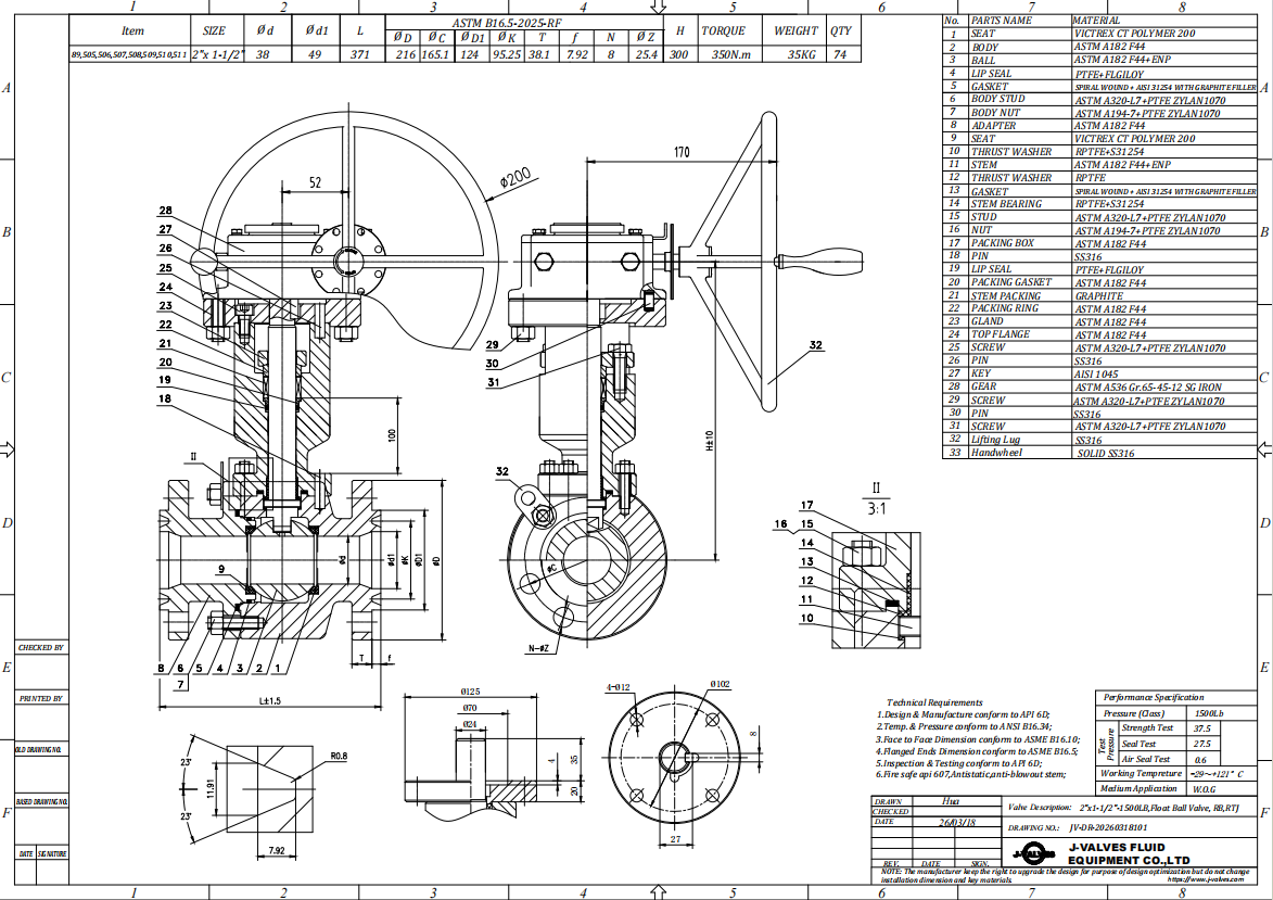
Overview of the J-VALVES DN50 x 40 Class 150 Stainless Steel Floating Ball Valve
This is a two piece floating ball valve with a reduced bore, forged in F2 stainless steel and flanged to ASME B16.5 Class 150. Both ends are DN50 and the through passage is DN40,
and the stem is extended so that the stuffing box and operator stand clear of the pipe insulation. It is built for the point on a lagged line where the medium matters as much as the temperature.
A105 carbon steel suits clean steam and clean hot
water but corrodes on chlorides, dilute acids and any product where iron contamination must be excluded. Forging the same body in F2 answers that without changing the face to face length or the bolt pattern, so a stainless build is a substitution rather than a redesign.
The extension does one job only: it lifts the gland and the operator out of the insulation so the packing is not baked and the handle is not buried. It is neither cryogenic nor buried, and the three are not interchangeable. A valve selected on the wrong extension will fit the pipe and still fail to do what it was bought for.
A floating ball valve carries its ball on the two seat rings rather than on trunnions, so line pressure presses it into the downstream seat. Because the ball is free to move, a cavity that pressurises as trapped liquid warms pushes it off the upstream seat and vents upstream, which removes the piston effect seats, sealant injection points and cavity relief devices found on trunnion datasheets. Their absence is a design feature, not a cost reduction.
Design and Construction
The body is two halves joined on one machined joint with a spiral wound stainless and graphite gasket and a ring of bolts, a single main pressure joint. The ball and both seats come out once that joint is opened, which makes a seat change a workshop job rather than a replacement valve. The trade is that the body must move along the pipe axis, so the piping needs a flexible element or a spool with slack.
The forging has continuous grain flow and no shrinkage cavity or gas porosity, the defects that appear in a casting as a leak path through the wall or as a pocket that holds medium after a wash.
The ball is F304 or CF8 with hard chrome plating, optionally 316, and the stem is 304 or 316 stainless because it cannot be inspected in service. The stem is retained by the body rather than by the gland, so anti blow out does not depend on the packing, and the upper stem seal can be renewed with the valve closed and the cavity vented.
The stem passes through the extension as a continuous shaft, so the pressure boundary stays at the original stem and only the operating point moves, and a guide bush at the top carries the side load.
What F2 Means in a Valve Specification
F2 is the grade code this catalogue and this quotation system use, and the purchase order that says F2 is the one this valve is built to. Whether the code maps onto a named standard grade is a question for the material certificate, not the drawing title, so a buyer should ask for that certificate by heat number rather than accept the code alone.
The code also tells you how the alloy behaves. It is an austenitic stainless of the 18 chromium 8 nickel family, so it cannot be hardened by heat treatment and its wear resistance has to come from the surface, which is why the ball is hard chrome plated rather than through hardened. It work hardens quickly under the tool and conducts heat poorly, so roughing and finishing stay separate operations.
Its limit on a valve is pitting rather than tensile strength. The pitting resistance equivalent number comes to about 19 for this family, against about 26 for a molybdenum bearing grade such as F316L and 42 to 44 for a super austenitic forging such as F44. That gap separates a body that survives a chloride line from one that pits, and it is invisible on a quotation that says stainless steel.
The consequence is temperature dependent. Chloride stress corrosion cracking varies with chloride level, temperature and stress, so stay below roughly 60 C where chlorides are present, and move to a molybdenum bearing or duplex grade where that cannot be held. F2 suits condensate, demineralised water, boiler feed water and many dilute acids; it does not suit seawater, brine, hypochlorite or hot chloride streams.
Material Options
| Component | Standard Material | Optional Upgrade | Service Notes |
|---|---|---|---|
| Body and end | F2 forged stainless, annealed to A182 practice | F316 or F316L forging | Grade code F2, 18Cr-8Ni family, PREN about 19 |
| Ball | F304 or CF8 with hard chrome plating | F316 ball | Passivated, chrome 0.05 to 0.10 mm |
| Stem | 316 stainless steel | F316L or 17-4PH | Retained by the body, anti blow out |
| Seat | PTFE | RPTFE, PPL, PEEK | 200 C, 230 C, 260 C and 250 to 260 C limits |
| Stem packing | Flexible graphite | PTFE V rings | ISO 15848 qualified |
| Body gasket | Spiral wound SS316, graphite filler | PTFE envelope gasket | Renewed whenever the joint is opened |
| Bolting | A193 B8 with A194 8 nuts | B8M with A194 8M | Galling control required |
| Extended stem | 304 or 316 stainless shaft and housing | None | Length set by the insulation |
| Surface finish | Pickled and passivated to ASTM A380 | Internal Ra 0.8 micrometre | Free iron test on every body |
Stainless bodies are usually assembled with stainless bolting, because a carbon steel bolt in a stainless joint sets up a galvanic couple where a leak is least welcome. The trade is galling: stainless threads seize when tightened dry, so the assembly instruction must name a lubricant that suits both the medium and the alloy.
Technical Specifications
| Item | Value |
|---|---|
| Nominal size | DN50, NPS 2, at both flanged ends |
| Bore | DN40 reduced bore, 38 to 40 mm actual, per drawing |
| Pressure class | Class 150, catalogue label PN20 |
| Ambient rating | 19.0 bar (275 psi) at 38 C, B16.34 group 2.1 |
| Rating at 200 C | 15.9 bar (230 psi) |
| Rating at 400 C | 13.1 bar (190 psi) |
| Seat temperature limit | 200 C PTFE, 230 C RPTFE, 260 C PPL |
| Shell test | API 598, 28.5 bar with water |
| Seat test | API 598, 20.9 bar each seat, both directions |
| Flange | ASME B16.5 Class 150 raised face, 152.4 mm OD, 19.1 mm thick, 4 x 5/8 inch on 120.7 mm bolt circle |
| Face to face | 178 mm to ASME B16.10, the same as a Class 150 gate valve |
| Extended stem length | 200 mm to 800 mm typical, from the pipe centreline |
| Anti-static | 10 ohm or less, to API 608 |
| Fire safe | API 607 and ISO 10497 |
| Design standard | API 608, ASME B16.34 |
| Material certificate | EN 10204 3.1, heat number traceable |
The carbon body sits in B16.34 group 1.1 at 19.6 bar, the austenitic body in group 2.1 at 19.0 bar, about 3.5 per cent lower at the same class, and the gap widens with temperature. A quotation copying the carbon steel rating onto a stainless valve is quoting a number the material cannot support.
Standards and Compliance
The design basis is API 608, the standard written for general industrial ball valves and the correct basis for a floating ball design. API 6D appears on many quotations for this product but is written around trunnion mounted pipeline valves, and a datasheet listing the two side by side states two incompatible bases rather than two qualifications. The clauses that shape this valve are stem retention and electrical continuity from stem to body.
The pressure temperature rating comes from ASME B16.34 and follows the material group rather than the class alone. Group 2.1 covers the 18Cr-8Ni austenitic forging family, here the F2 forging, and at Class 150 gives 275 psi at 38 C, 230 psi at 200 F, 190 at 400 F, 140 at 600 F and 20 at 1000 F, which is why a stainless valve should never be specified by class number alone.
| Requirement | Standard | Supplied |
|---|---|---|
| Pressure temperature rating | ASME B16.34 group 2.1 | 275 psi at 38 C, 20 psi at 1000 F |
| Flange dimensions | ASME B16.5 | Class 150 raised face |
| Face to face | ASME B16.10 | 178 mm at NPS 2 |
| Shell and seat test | API 598 | 28.5 bar and 20.9 bar |
| Fire safe | API 607, ISO 10497 | 30 minute burn, re-tested |
| Fugitive emission | ISO 15848-1 | Qualified stem seal |
| Passivation | ASTM A380 | Free iron test on every body |
| Documentation | EN 10204 3.1 | Heat number traceability |
The PN20 label needs a warning. It is the metric reference that ISO 7005 uses for the Class 150 pound rating, not one of the EN 1092-1 pressure steps, which end at 16 and resume at 25. At DN50 an EN 1092-1 PN16 flange is 165 mm across on a 125 mm bolt circle with four M16 bolts, while this valve carries an ASME B16.5 Class 150 NPS 2 flange on a 120.7 mm bolt circle with four 5/8 inch bolts. The circles differ by 4.3 mm and the threads are inch against metric, so the two will not bolt together.
Manufacturing and Quality Control
Bodies and covers are forged, annealed and machined at the J-VALVES plants in Wenzhou and Lishui, a 15000 square metre base with 40 CNC lathes, 5 machining centres and 8 drilling machines. Seat pockets, bore, stem bore and flange faces are cut against the drawing, because seat pocket concentricity and face to face length set both sealing and fit on site.
The finish inside the bore is a specification item, not an aesthetic one. A roughened bore holds product, and on a hygienic or chemical line that starts a contamination problem. Internal surfaces are finished to about Ra 0.8 micrometre where the enquiry calls for it, and the body is pickled and passivated to ASTM A380 before assembly.
| Step | What Is Checked | Standard or Acceptance |
|---|---|---|
| Incoming material | Heat number, chemistry, mechanical certificate | EN 10204 3.1, F2 grade and heat traceable |
| Solution annealing | Temperature record and quench method | 1040 to 1120 C, rapid cool |
| Machining | Seat pocket, bore, flange face, stem bore, Ra | Dimensional and surface report |
| Passivation | Free iron, surface condition | ASTM A380, ferroxyl test |
| Assembly | Gland torque, ball rotation, anti-static path | Torque and continuity record |
| Shell test | 28.5 bar with water, chloride free | Test certificate |
| Seat test | 20.9 bar, each seat, both directions | Test certificate |
| Final | Operation, marking, packing | Certificate of conformity |
One process point is easy to get wrong. Testing a stainless valve with tap water leaves chloride laden residue in the cavity and seat pockets that initiates pitting during storage and commissioning, so test water for a stainless build must be controlled for chloride content and the valve drained and dried afterwards.


Applications and Industry Service
The natural home is a lagged or traced line with a corrosive or product sensitive medium. Demineralised water and boiler feed systems use it because a carbon body would shed iron oxide into water kept free of ions, and food, beverage and pharmaceutical lines use it where the body must be cleanable and passivated.
The limits matter as much as the applications. Seawater, brine, hypochlorite dosing and hot chloride streams belong to a 316 or duplex valve. Where the medium is abrasive as well as corrosive, the trim needs more than chrome on a soft seat. Where the temperature runs past 260 C the seat is the limit and a metal seated valve or another family is right. Where the line is buried or cryogenic, the extension changes and this build is wrong.

Installation, Operation and Maintenance
Before installation, remove the flange protectors, check that the bore and flange faces are clean, and cycle the valve once to confirm that the ball turns freely and the stops are set at both ends. The valve is bidirectional, so it fits either way round, but the extension should end up within reach. Check it against the actual lagging thickness before the insulation is closed up, the last moment a short extension is cheap to correct.
Stainless faces gall and crevice corrode more readily than carbon, and the gasket must suit the medium rather than the pressure alone: spiral wound with graphite filler generally, a PTFE envelope where graphite contamination is unacceptable. Bolts are tightened in a crossing sequence in two passes and rechecked after the first thermal cycle.
Operation is a quarter turn, clockwise to close, with the lever or wheel stopping against a mechanical stop rather than the end of the ball travel. On a valve operated rarely, cycle the ball a few times a year, because a ball sitting against one seat takes a set in the soft seat and needs more breakaway torque.
Maintenance is concentrated above the insulation: the gland can be re-energised through the extension housing without removing lagging, and the upper stem seal renewed with the valve in line once it is closed and the cavity vented. Stainless packing boxes tolerate over tightening poorly, so bring the gland up in small increments.
A seat replacement is a body joint job: isolate, vent and drain both sides, confirm the cavity is at atmospheric pressure, open the joint, renew both seats and the body gasket, and retorque in sequence. Opening the joint breaks the pressure boundary, and its faces must be checked for crevice corrosion and galling before the new gasket goes in.
How to Specify and Order
An enquiry should state the nominal size and reduced bore, the pressure class, the body and trim material by grade rather than by the word stainless, the end connection and facing, the face to face standard, the seat grade, the operator, and the extension length from the pipe centreline to the top flange. Write the body as F2, and name F316 where chlorides call for it.
State the medium with its chloride content and its temperature, not just its name, since those two numbers decide whether F2 is adequate. State the internal finish if the line is hygienic, whether a free iron test certificate is required, and the insulation thickness.
Standard builds are accepted from one piece, with 2 to 4 weeks for a standard configuration and 4 to 8 weeks for a custom build. Documentation is EN 10204 3.1 with heat number traceability, and a 3.2 certificate witnessed by a third party inspector is available where the project calls for it.
FAQ
Q: Why is the body forged in F2 instead of cast?
A: The cast equivalent sits in the same 18Cr-8Ni family and the same ASME B16.34 material group, so the pressure rating is identical, and the difference is soundness. A closed die forging has continuous grain flow and no shrinkage cavity or gas porosity, and a casting can carry both as a leak path through the wall or as a pocket that holds medium after a wash. On a hygienic or chemical line that pocket is a contamination risk and a crevice where chlorides start pitting, so at DN50, where a forging is also the cheaper route, the forged body is the better answer.
Q: What does F2 mean on the quotation, and what is the PREN?
A: F2 is the grade code this catalogue uses for the forged 18Cr-8Ni austenitic body of this valve, and the material certificate behind it names the matching standard grade. Its pitting resistance equivalent number comes to about 19, against about 26 for F316L and 42 to 44 for a super austenitic grade such as F44. PREN predicts resistance to pitting and crevice corrosion in chloride service, so a value near 19 means the alloy suits mildly corrosive media at moderate temperature and does not suit seawater, brine or hypochlorite. As a rule, keep the chloride level low and stay below roughly 60 C where chlorides are present, and move to 316 or duplex where either cannot be held.
Q: Is this valve rated the same as a carbon steel Class 150 valve?
A: No, and the gap is small enough to be missed. This body is in ASME B16.34 group 2.1, rated 275 psi (19.0 bar) at 38 C at Class 150. A carbon steel body in group 1.1 is rated 285 psi (19.6 bar), about 3.5 per cent higher, and the difference widens as the temperature climbs because the allowable stress of the austenitic grade falls away faster. A quotation that copies the carbon steel figure onto a stainless valve is quoting a number the material cannot support.
Q: Does the extended stem make this a buried valve?
A: No. An extended stem is fitted for three different reasons that are not interchangeable. A cryogenic extension holds a still gas column so the packing stays above freezing. A buried extension brings the operator up to finished ground level inside a valve box and is much longer. This extension does the third job: it lifts the gland and the operator out of the pipe insulation on an above ground hot line. State the duty and the lagging thickness on the enquiry, because the length, the coating and sometimes the valve family change with the answer.


Hot Products


News
Ball Valves in Geothermal Brine: Silica Scale, Chloride Cracking And The Cooling Trap
Why geothermal brine destroys ball valves: retrograde silica scale, calcite at the flash point, chloride cracking above 60 C and the 250 C seat limit.
Read More
Ball Valve Face To Face Dimensions: Why A Correctly Ordered Replacement Still Does Not Fit
A 6 inch Class 150 ball valve can be 267 or 305 mm face to face and both are compliant. How B16.10, EN 558 and flange drilling decide whether it fits.
Read More
Ball Valve Stem Key And Keyway: What Gives Way First, And What The Handle Cannot Tell You
Between the handle and the ball there are four fits. Which one shears, which one cracks, and how a few degrees of lost motion hides a valve that never seated.
Read More
Ball Valve Datasheet: Six Blocks That Decide Whether Two Quotes Are Comparable
A ball valve datasheet only works when six blocks are fixed: pressure basis, bore, temperature ceiling, test, end connection, operator. How each is written.
Read More