


CHINA J-VALVES Offers Various High-quality I ndustrial Ball Valves
J-VALVES, a distinguished professional ball valve manufacturer rooted in China, takes pride in its extensive product portfolio. Our offerings span a wide range, including trunnion-mounted ball valves, floating ball valves, high-temperature ball valves, high-pressure ball valves, metal-sealed ball valves, ultra-low temperature ball valves, DBB ball valves, Three-way And Four-way Ball Valve, and fully welded ball valves. Each product is a testament to our commitment to precision engineering and reliable performance. Meticulously crafted, they are designed to not only meet but exceed the most stringent industrial demands, ensuring stable operation even under extreme conditions. This enables us to provide our clients with high-value services and makes our valves widely sought-after in industries.
Product Category
Contact Us


-
J-VALVES-Q41F
-
J-VALVES
Overview of the J-VALVES 1/2 Inch Class 300 CU5MCuC Floating Ball Valve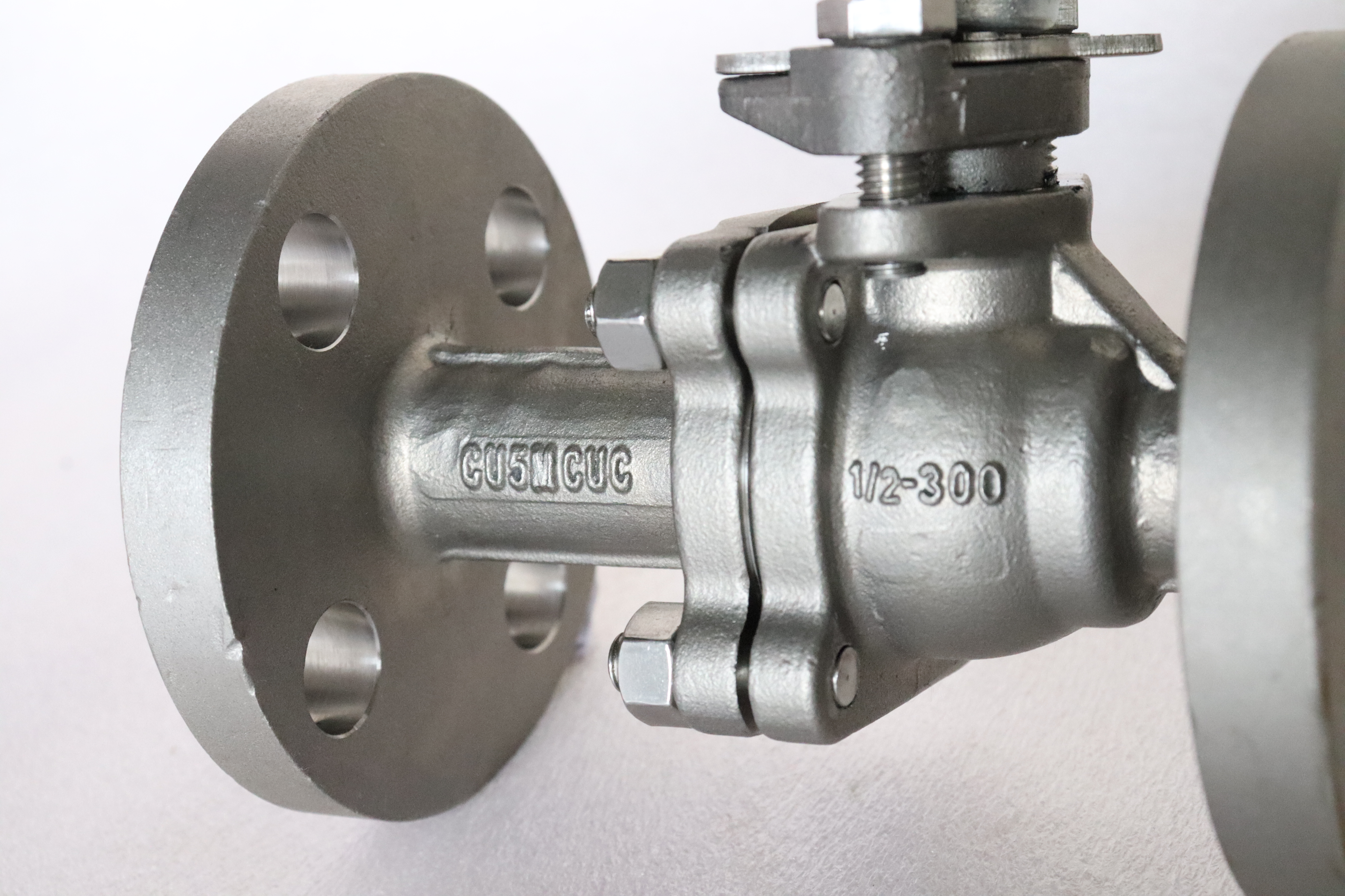
This is a half inch, Class 300, two-piece flanged floating ball valve with a full port and a lever, and the one thing that separates it from every other half inch valve on the shelf is the body: it is cast in ASTM A494 CU5MCuC, UNS N08826, a nickel-iron-chromium alloy with molybdenum, copper and niobium. The same family in wrought form is known as Alloy 825, and that sentence is where most of the confusion on this product starts, so this page comes back to it more than once.
At this size the pressure is not the problem. A half inch Class 300 body is a small, thick walled lump of metal, and the class says more about the flange than about the difficulty of the job. The medium is the problem. A valve this size usually sits on a chemical injection line, a sample point, a gauge root or an acid unloading connection, where the flow is a trickle and the consequence of a leak is a shutdown, an exposure or a reportable release. The alloy is bought for that, not for the class.
Two-piece construction, two soft seats and a quarter turn lever are all that the duty needs. The end cap is small enough to handle by hand, the ball is small enough that line pressure holds it against the downstream seat without any assistance, and the lever is short because the torque is low. What a buyer is really choosing on this page is the body alloy, the seat material and the paperwork. The rest of the page is about those three.
Design and Construction
Two piece means a main body and one end cap, closed on a single gasketed joint and held by a circle of bolts. The end cap is the assembly opening: the ball goes in through it, one seat goes in behind the ball, and the other seat is set into the main body. That is the whole reason the body is split. It also means the joint is not a detail, because the gasket that seals it is a wetted part sitting in the same medium as the body.
The ball floats. It is not carried on trunnions and it has no bearings; line pressure pushes it downstream until it lands on the downstream seat, and that contact is the seal. Two seats face each other, so the valve shuts off from either direction, and the cavity between them is closed when the ball is shut. If trapped liquid expands, the upstream seat lifts off and the excess goes back into the upstream line, which is why this design needs no relief device, no piston seat and no injection port.
The stem is fitted from inside the body. The collar on the stem is wider than the bore in the neck, and that collar is what stops the stem being blown out when packing fails; the consequence is that the stem has to be inserted through the body cavity before the ball and the end cap go on. The gland bolts to the neck above it. So there are two different maintenance answers on this valve: the gland is reachable, the stem is not, unless the body joint is opened.
The gland is a bolted plate over a stack of packing rings, and it can be tightened while the valve is in service. Packing can also be renewed with the line isolated and the cavity vented, without taking the valve out of the pipe. Nothing else can be done under pressure, and it is worth being blunt about that, because catalogue language around two piece valves often suggests otherwise: the body joint is a pressure boundary, and opening it means the line is isolated and drained.
The joint carries the full class pressure across two machined faces and a thin gasket. On a valve in a benign medium that gasket is a lifetime part. In acid, sour brine or a solvent it is a scheduled item, and its material has to be chosen with the same care as the body. A spiral wound gasket with stainless windings is a wetted stainless part; putting one in a nickel alloy valve reintroduces exactly the corrosion the body was bought to avoid.
The lever turns a quarter turn between two stops. The stops are part of the neck and the lever, so the ball cannot be over travelled, and a locking hole can be added so that the open or closed position can be padlocked, which matters on an isolation point that a permit to work depends on. At half inch the lever is short and the operating effort is low, and that is the honest reason this size is used as a barrier rather than as a regulating device.
What it is not: a throttle. A soft seat asked to hold a part open position is being eroded by the same fluid it is meant to seal against, and the damage shows up as a leak long before it shows up as noise. It is also not a double block and bleed valve, because the two seats are not independent barriers that can be verified one at a time, and it is not a slurry valve at any size.

Material Options
Casting is the right process here for a reason that has nothing to do with cost per kilogram. The alloy is expensive, the shape is a pair of flanges with a neck and a cavity between them, and machining that shape out of bar would turn most of the purchased alloy into chips. Near net shape casting keeps the expensive material where the pressure is. The trade is that a casting has to be qualified as a casting: chemistry per heat, heat treatment per heat, and non destructive testing wherever the drawing asks for it.
The composition explains the applications. Nickel at 38 to 44 percent is what makes the alloy resistant to chloride stress corrosion cracking, the failure mode that takes austenitic stainless out of hot chloride service. Chromium at 19.5 to 23.5 percent covers oxidising conditions. Molybdenum at 2.5 to 3.5 percent is there for pitting and crevice corrosion resistance in chlorides and for reducing acids. Copper at 1.5 to 3.5 percent is the addition that makes the alloy useful in sulfuric acid, and niobium stabilises it against sensitisation. None of those four does the job alone, which is why substituting a super austenitic stainless or a duplex grade is not a like for like swap.
The table below lists the wetted path. The rule applied on this valve is simple: no part of the wetted path should be less resistant than the body. That rule is easy to state and easy to break, because the ball, the stem and the seat are the cheapest parts to change and the easiest to take from stock. A nickel alloy body with a hard chrome carbon steel ball is not a nickel alloy valve; it is a carbon steel valve with an expensive shell, and the medium will find the ball first.
| Component | Standard Material | Optional Upgrade | Service Notes |
|---|---|---|---|
| Body | ASTM A494 CU5MCuC, UNS N08826, solution annealed | None offered on this page | The pressure boundary; grade, UNS number and heat number are fixed at order |
| End cap | Same grade and heat treatment as the body | Cast from the same heat when the order asks | Second casting, same wetted surface, one more machined face |
| Body joint gasket | PTFE sheet, or spiral wound with an alloy winding | Flexible graphite for fire and high temperature | A wetted part; stainless windings defeat the purpose of the body alloy |
| Ball | Quoted with the medium, never less resistant than the body | Hard chrome or nickel plating where the medium allows | The part the medium touches most; named on the 3.1 certificate |
| Stem | Quoted with the medium, anti blowout collar | Not applicable | Fitted from inside, so renewal means opening the body joint |
| Seat rings | PTFE, RPTFE or PPL | Metal seat, quoted against the duty | Sets the temperature and the leakage class, not the alloy |
| Stem packing | PTFE rings | Flexible graphite | Adjustable in service; graphite where fire safe is required |
| Bolting | Alloy steel, coated | Stainless | Not wetted, but it is the external corrosion path |
| Lever | Steel, plated | Stainless, with a locking hole | Quarter turn between two stops |
The seats are polymer as standard, PTFE, RPTFE or PPL, with a metal seat quoted against the duty. On this valve the seat is what limits the temperature, not the alloy, and it is also what limits the chemistry: a polymer seat in a solvent that swells it will fail while the body is untouched. The alloy ceiling is far above the polymer ceiling, and a data sheet that quotes the alloy figure for the whole valve has quoted the wrong part of it.
Technical Specifications
The table below is the ordered data. Two entries are worth reading carefully. The rating is not copied from a carbon steel data sheet: the allowable pressure for a Class 300 valve comes from the ASME B16.34 table row that names this alloy material group, and a sheet that quotes the carbon steel figure has not checked the right row. The flange entries are the opposite case, pure table values from B16.5 for NPS 1/2 Class 300: 95.2 outside diameter, 66.7 bolt circle, four bolts, 34.9 raised face.
| Item | Value | Basis |
|---|---|---|
| Product type | Two piece flanged floating ball valve, full port | Photograph and section drawing |
| Size | 1/2 inch, DN15 | Original parameter sheet, first line |
| Pressure class | Class 300, recorded as PN 50 in API 6D clause 7.2 | API 6D, clause 7.2 |
| Allowable pressure | Taken from the ASME B16.34 row for this alloy group | ASME B16.34, table for the group named on the data sheet |
| Body material | ASTM A494 CU5MCuC, UNS N08826, solution annealed | Customer material confirmation and the casting certificate |
| End connection | Flanged, ASME B16.5 Class 300, raised face | ASME B16.5 |
| Flange geometry | 95.2 outside diameter, 66.7 bolt circle, four bolts, 34.9 raised face | ASME B16.5, NPS 1/2 Class 300 |
| Face to face | ASME B16.10 value for this type and class, confirmed on the signed GA drawing | ASME B16.10 |
| Port | Full port, 1/2 inch nominal | API 608 |
| Seat | PTFE standard, RPTFE or PPL on request | Original parameter sheet |
| Leakage acceptance | Zero visible leakage, soft seat | API 598 |
| Operation | Lever, quarter turn, locking device on request | Photograph |
| Design standard | ASME B16.34 and API 608 | API 608 scope |
| Test standard | API 598 | API 598 |
| Fire test | API 607, equivalent to ISO 10497 | Test report on the assembled valve |
| Certificate | EN 10204 3.1, heat number matching the body marking | Purchase order |
One property of that flange is worth knowing before quotations are compared. At NPS 1/2, B16.5 gives Class 300 and Class 600 the same outside diameter, the same bolt circle and four bolts in the same positions. At the pipe interface, the flange on a half inch Class 300 valve and the flange on a half inch Class 600 valve are the same part. It follows that a joint made of a Class 300 valve between two Class 600 flanges is dimensionally possible, and that the joint is then rated by the weaker component rather than by the pipe. It also follows that the flange tells you nothing about the class of the valve behind it. Read the marking on the body, not the bolt pattern.
Standards and Compliance
Two documents govern the design and they do different jobs. ASME B16.34 gives the wall thickness and the pressure temperature ratings, which is to say it tells you how much metal and how much pressure. API 608 is the product standard for flanged, threaded and welding end ball valves with metal bodies and soft or metal seats, and it is the correct product standard for a floating ball valve. API 6D, which appears on a great many floating ball pages, is the pipeline valve standard built around trunnion mounted and fully welded bodies; on this page it is used for exactly one thing, the PN 50 designation in clause 7.2.
| Requirement | Standard | What It Covers |
|---|---|---|
| Pressure retaining design | ASME B16.34 | Wall thickness and the pressure temperature rating for the alloy group |
| Product standard | API 608 | Floating ball valve with flanged ends, anti static and fire test requirements |
| Flange dimensions | ASME B16.5, NPS 1/2 Class 300 | Outside diameter, bolt circle, bolt holes and raised face |
| Face to face | ASME B16.10 | End to end for the valve type and class |
| Pressure test | API 598 | Shell at 1.5 times the rating, seat at 1.1 times |
| Fire test | API 607, ISO 10497 | A test on the assembled valve, not a design clause |
| Casting grade | ASTM A494 CU5MCuC, UNS N08826 | Chemistry and mechanical properties of the cast heat |
| Casting soundness | Supplementary PT and RT on the purchase order | Penetrant on the pressure boundary, radiography at the joint |
| Marking | Grade, heat number, size and class on the body | Traceability from the body back to the certificate |
Testing is API 598: shell test at 1.5 times the rating, seat test at 1.1 times, and a soft seated valve is expected to show nothing at the seat during the hold. The test medium matters on this alloy. Water with a high chloride content, left in the cavity after the test, is a poor way to begin the life of a corrosion resistant valve, so the test water is specified low in chloride and the body is drained and dried before the caps go on.
The casting standards are where the honest conversation happens. ASTM A494 covers the chemical composition and the mechanical properties of the cast grade, and a certificate to that standard is a statement about a test bar poured with the heat. It does not by itself put a penetrant test or a radiograph on every pressure boundary. Those are supplementary requirements, ordered rather than assumed. On a half inch body the wall is thin and the joint and the neck are the two places where shrinkage is most likely, so if the duty is sour or the medium is an acid, the purchase order should ask for PT on the pressure boundary and RT at the joint, and the report should arrive with the certificate.
The PN 50 marking needs one sentence and no more. API 6D records Class 300 as PN 50, so the number belongs on the valve and on the data sheet; EN 1092-1 has no PN 50 step at all, so anyone using that number to buy a mating flange is looking for a flange that does not exist.
Manufacturing Process
The body is sand cast. Two details in the foundry matter more than the rest on this alloy: sulphur and phosphorus are held low, because both are tolerated by the corrosion resistance in much smaller amounts than by the strength, and the risers are placed at the flange rings and the neck, where the section is thickest and where a shrinkage cavity would sit either in a sealing face or in the stem bore.
Every heat is solution annealed and the chart is kept. Casting leaves a segregated, dendritic structure, and annealing dissolves the phases that segregation produces and restores both ductility and corrosion resistance. A nickel alloy casting that was never annealed can pass a hydrostatic test and still crack in service, which is why the heat treatment record is part of the inspection file and not part of the packing list.
Machining is arranged around the sealing faces. The two flange faces and the body joint face are cut in the same setup so that they stay square to one another, the ball is ground and lapped, and the seat pockets are machined to match the seats that were made for that ball. On a valve this small the machining is a larger share of the hours than the casting, and it is also where the difference between a valve that seals first time and one that needs a second attempt is decided.
Assembly is done clean. Free iron is the specific enemy: carbon steel tooling, wire brushes or a machine tool that also runs carbon steel will leave particles in the surface of a nickel alloy, and those particles rust. The valve is assembled, tested with low chloride water, drained, dried and capped, and it leaves the works bare, because a nickel alloy does not need a paint system to survive storage. The marking is struck, and the certificate is compiled from the same heat numbers that are on the body.

Quality Control and Testing
Three checks decide whether a CU5MCuC valve is what it says it is: chemistry per heat, positive material identification on the finished body, and a documented heat treatment. Identification is unusually effective on this alloy. A handheld XRF reads nickel at 38 to 44 percent and copper at 1.5 to 3.5 percent without difficulty, so a body that is actually austenitic stainless or duplex is caught in seconds rather than by a laboratory. What the instrument cannot see is carbon, so the carbon figure has to come from the certificate, and the certificate has to name the cast grade rather than the wrought one.
| Check | Method | Acceptance |
|---|---|---|
| Chemical analysis | Spectrometer on a test bar from the heat | Composition inside the A494 range for CU5MCuC |
| Heat treatment | Chart from the solution annealing furnace | Temperature and holding time recorded for every heat |
| Positive material identification | Handheld XRF on the finished body | Nickel and copper consistent with UNS N08826 |
| Surface examination | Penetrant test on the pressure boundary when ordered | No linear indication on cast or machined surfaces |
| Radiography | Film or digital at the body joint and the neck when ordered | No shrinkage porosity in the joint section |
| Machining | Flange and joint faces checked for flatness and squareness | Faces seal on the gasket without lapping on site |
| Pressure test | Shell at 1.5 times the rating, seat at 1.1 times, to API 598 | No leakage; the soft seat shows nothing on the seat test |
| Anti static | Resistance measured from ball to stem to body | Continuous path, no isolated component |
| Marking and documents | Visual check against the drawing and the certificate | Grade, UNS number, heat number, size and class agree |
The rest of the routine is conventional but not optional: penetrant or radiographic examination where the order asks for it, hydrostatic testing at the API 598 values with low chloride water, anti static continuity measured rather than assumed, seat leakage observed and recorded, and then marking and a certificate that carries the same heat number that is stamped on the body. A buyer who wants to check the one thing that matters most can compare those two numbers and stop there.

Applications and Industry Service
Sulfuric acid is the duty the copper addition exists for, and it covers a wide band of concentration and temperature, including dilute streams, spent acid and acid handling on a small bore. Phosphoric acid from the wet process is the second: it carries chlorides, fluorides and solids, and it is one of the few duties where this combination of molybdenum and copper is worth more than a higher molybdenum grade without copper.
Sour service is the third: hydrogen sulphide, carbon dioxide and chlorides together, where austenitic stainless fails by chloride stress cracking and carbon steel fails by general loss and pitting. Brine, produced water and polluted seawater belong in the same group, as do scrubber liquors and reagent lines in flue gas desulphurisation, which are chloride bearing, aerated, and often at the temperature where chloride cracking begins.
Where it stops matters as much as where it works. Wet chlorine and hypochlorite need a higher molybdenum nickel alloy. Hot concentrated sulfuric acid is beyond the copper bearing grades. Strongly oxidising acids are handled more economically by a molybdenum free austenitic. Abrasive slurries are out of the question for any soft seated valve, whatever the body is made of. And high temperature strength is not the reason to buy this alloy; if that is the requirement, the conversation is about a different material family.
On instrument and sampling duty the valve is a barrier, not a regulator, and the small volume between the two seats holds a plug of the medium whenever the valve is shut. If that medium crystallises or polymerises, that plug is where it will do it, so the line should be arranged to drain or flush, and the general arrangement drawing should show how the cavity is emptied before maintenance.
Installation, Operation and Maintenance
Orientation is free on this valve. Two things matter more than the angle: the gasket material must suit the medium, and the joint must be closed with the valve supported and the two flange faces parallel. Bolts are tightened in a cross pattern in stages, which is ordinary practice and is also the difference between a joint that holds for years and one that weeps at the first thermal cycle.
Hold the valve with a wrench on the body or on a flange when the pipe is made up, and never counter hold on the lever or on the neck. The neck carries the gland and the stops, and a pipe wrench on it will mark the alloy and can load the stem. Two wrenches, one on each side of the joint, is the whole instruction.
Operation is a quarter turn. Leave the valve fully open or fully closed; a soft seat held part open is being cut by the flow. The lever is not a step, not a lifting point and not a place to hang anything except a lock through the hole provided for it.
Maintenance splits into what can be done live and what cannot. The gland can be tightened live, and packing can be renewed with the line isolated and the cavity vented. Everything else, including the stem and both seats, needs the body joint open, which means the line is isolated, drained and purged. In a nickel alloy valve that repair is usually worth doing rather than replacing, but it is not an in line job, and a maintenance plan that assumes otherwise will be written around a valve that cannot be worked on.
Storage is short and specific. Keep the caps on, do not store the valve wet, and keep carbon steel tooling and wire brushes away from the machined faces. Free iron embedded in a nickel alloy surface becomes a rust spot, and a rust spot on a nickel alloy valve is the first thing an inspector photographs.
How to Specify and Order
The grade alone does not select the valve. Six answers decide it: the medium and its concentration, the temperature, the chloride content, whether the stream is aerated, the flow, and whether the line is dead ended. Two lines carrying the same nominal acid at the same temperature can need different alloys because one is aerated and the other is not, or because one runs continuously while the other sits full of stagnant liquid for weeks at a time.
The order should read: body ASTM A494 CU5MCuC, UNS N08826, solution annealed; size 1/2 inch; Class 300; full port; flanged to ASME B16.5 Class 300 raised face; seat material by name; ball and stem material by name, with the rule that neither is less resistant than the body; test to API 598 with low chloride water; penetrant and radiographic examination if the duty needs it; EN 10204 3.1 certificate; and marking to match.
One warning about documents. A certificate for Alloy 825, UNS N08825, is not a certificate for a CU5MCuC casting, UNS N08826. They are the same family and they are not the same product: the cast grade has its own UNS number, its own mechanical property requirements and its own non destructive testing. If a supplier offers a wrought certificate against a cast body, the paperwork is describing a different object, and the review should stop at that point rather than at the end of the file.
FAQ
Q: Is CU5MCuC the same material as Alloy 825?
A: Only in family. CU5MCuC is the casting grade under ASTM A494 with UNS number N08826, and Alloy 825 is the wrought grade with UNS number N08825. The chemistry is close, the product form is not, and neither is the acceptance. A494 sets the composition and the mechanical properties of a test bar poured with the heat; it does not put a penetrant test or a radiograph on the pressure boundary unless the order asks for it. A wrought certificate presented against a cast body describes a different object, so the purchase order should read A494 CU5MCuC and N08826, and the report should carry the same heat number that is stamped on the body.
Q: Which media is this valve for, and where does it stop?
A: It is for sulfuric acid over a wide band of concentration and temperature, for wet process phosphoric acid, for sour gas carrying chlorides, for brine, produced water and desulphurisation liquor. It is not for wet chlorine or hypochlorite, which need a higher molybdenum nickel alloy, not for hot concentrated sulfuric acid, and not for abrasive slurry at any size. The boundary is set by concentration, temperature, chloride level and aeration together, so the answer has to come from a corrosion chart for the actual stream rather than from one sentence on a data sheet.
Q: The body is the expensive part, so why are the seats the limiting item?
A: Because a polymer seat gives up long before a nickel alloy does. PTFE, RPTFE and PPL cap the temperature a long way below the alloy limit, and a solvent that swells or extracts the seat will pass every corrosion test on the body while the valve stops sealing. That is also why the ball, the stem and the gasket are quoted with the medium instead of being taken from stock: the rule on this valve is that nothing in the wetted path is less resistant than the body.
Q: When should I not buy this alloy?
A: When the medium is benign. A half inch Class 300 valve in carbon steel costs a fraction of this one and does the same job on water, air, steam, oil and dry gas, and the class is available in either material. The alloy is bought for the medium, not for the pressure, and a project that specifies it on a utility line is paying for corrosion resistance it will never use.


Hot Products


News
Ball Valves in Geothermal Brine: Silica Scale, Chloride Cracking And The Cooling Trap
Why geothermal brine destroys ball valves: retrograde silica scale, calcite at the flash point, chloride cracking above 60 C and the 250 C seat limit.
Read More
Ball Valve Face To Face Dimensions: Why A Correctly Ordered Replacement Still Does Not Fit
A 6 inch Class 150 ball valve can be 267 or 305 mm face to face and both are compliant. How B16.10, EN 558 and flange drilling decide whether it fits.
Read More
Ball Valve Stem Key And Keyway: What Gives Way First, And What The Handle Cannot Tell You
Between the handle and the ball there are four fits. Which one shears, which one cracks, and how a few degrees of lost motion hides a valve that never seated.
Read More
Ball Valve Datasheet: Six Blocks That Decide Whether Two Quotes Are Comparable
A ball valve datasheet only works when six blocks are fixed: pressure basis, bore, temperature ceiling, test, end connection, operator. How each is written.
Read More