


CHINA J-VALVES Offers Various High-quality I ndustrial Ball Valves
J-VALVES, a distinguished professional ball valve manufacturer rooted in China, takes pride in its extensive product portfolio. Our offerings span a wide range, including trunnion-mounted ball valves, floating ball valves, high-temperature ball valves, high-pressure ball valves, metal-sealed ball valves, ultra-low temperature ball valves, DBB ball valves, Three-way And Four-way Ball Valve, and fully welded ball valves. Each product is a testament to our commitment to precision engineering and reliable performance. Meticulously crafted, they are designed to not only meet but exceed the most stringent industrial demands, ensuring stable operation even under extreme conditions. This enables us to provide our clients with high-value services and makes our valves widely sought-after in industries.
Product Category
Contact Us

-
J-VALVES-Q647F
-
J-VALVES
Overview of the J-VALVES DN500 PN100 WCB Pneumatic Three Piece Ball Valve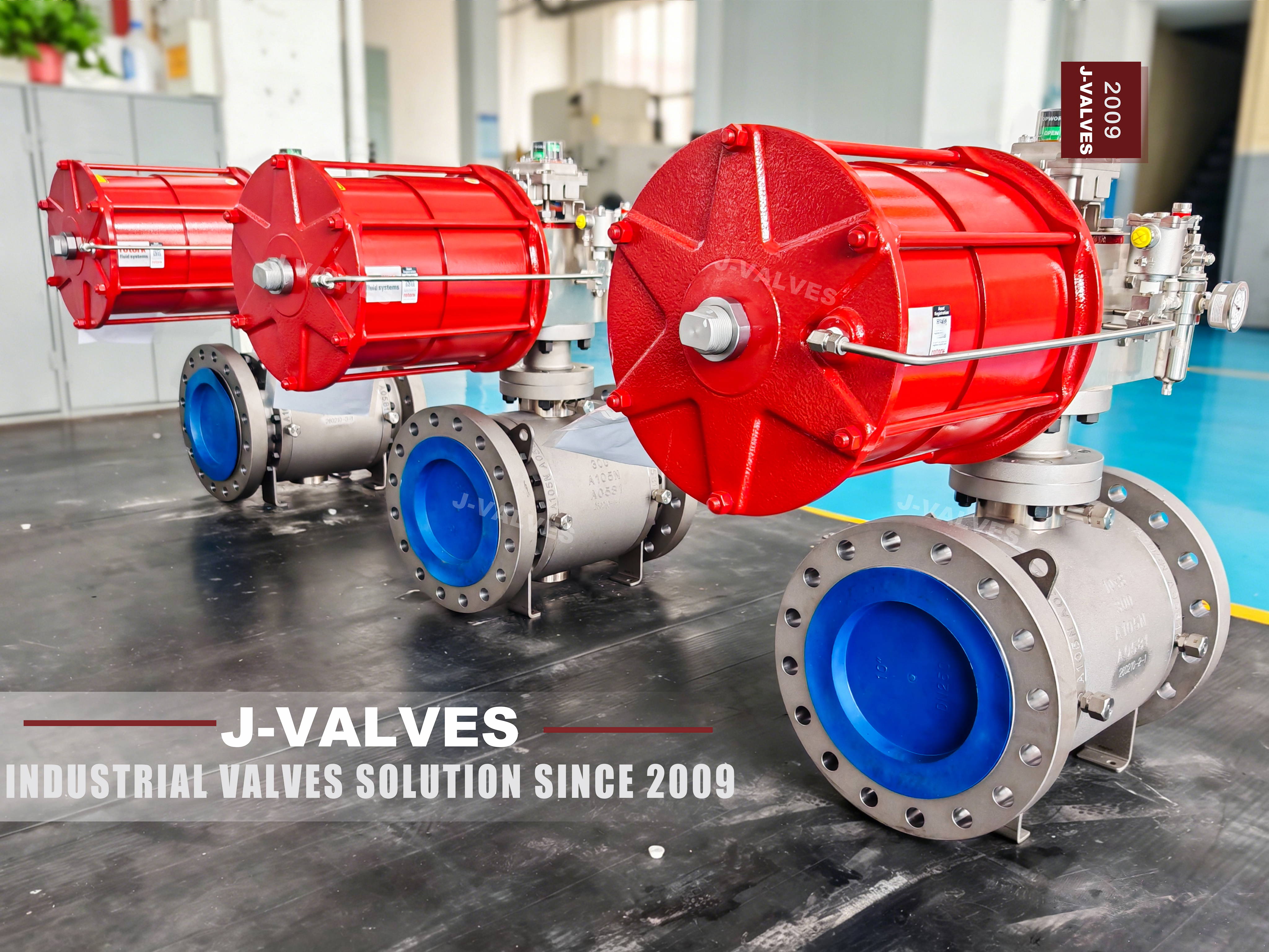
This is a twenty inch, DN500, three piece trunnion mounted ball valve with a cast carbon steel body to ASTM A216 WCB, a full bore, soft seats arranged as double piston effect by default, and a quarter turn pneumatic actuator. It is rated Class 600, which the current page also writes as PN100, and the two callouts belong to the same class even though the two numbers are not the same number. That is the first thing worth settling, because it decides whether the valve will bolt to the pipe it was bought for.
API 6D lists PN 100 against Class 600 in its pressure designation table, so the class is not in doubt. What differs is the arithmetic behind the two marks and the flange that follows from it. ASME B16.34 rates a Class 600 valve in group 1.1 material, which includes WCB, at 102.1 bar at 38 C, while PN 100 is a nominal designation under EN 1092-1 carrying a 100 bar reference. Two valves, one marked Class 600 and one marked PN 100, therefore claim the same class while sitting on different flange standards: B16.5 drilling on one side, EN 1092-1 drilling on the other, with a different bolt circle and bolt count for the same nominal size. They are not interchangeable at the flange, and no adapter makes them so.
The valve is not a floating ball valve: at DN500 Class 600 the seat load a floating ball would generate is one the seat ring cannot be asked to carry, the ball is carried on trunnions, and the thrust goes into bearings. It is not a two piece body, which has one pressure retaining joint instead of two, and it is not a subsea or wellhead valve, both of which the current page cites through API 6DSS and API 6A. What it is, is the block valve at the inlet and outlet of a station: either side of a pig trap, the suction and discharge of a compressor, the isolation valve on a metering run, the manifold valve in a tank farm. The actuator is there because those valves are operated remotely or by an emergency shutdown signal, and a twenty inch Class 600 valve is not opened by hand in a hurry.
Design and Construction
The body is in three parts: a left body, a centre section and a right body, held by two sets of studs with a gasket in each joint. The ball and both seat rings sit in the centre section, which is the part that comes out for maintenance. The point of the arrangement is that the centre section leaves along the pipe axis while both end bodies stay bolted to the line, so the pipe is not cut, not re-welded and not re-aligned. The alternative is a two piece body, where the ball and seats come out through one end and the pipe has to be spread far enough to clear the assembly, which at this size is a rigging job on the line rather than a job on the valve.
What the pattern costs is a second pressure retaining joint: two gasketed studded joints instead of one, two sets of fasteners to torque, two places where a leak can start, and a centre section heavy enough at DN500 to need lifting gear. That trade is why three piece bodies are rare on small valves and common on large ones. At DN20 the second joint buys nothing; at DN500 it buys the difference between a maintenance task and a pipe modification.
The ball is trunnion mounted. Two trunnions run in bearing blocks in the body and the bearings take the thrust that line pressure puts on the ball, so the seats are only asked to hold sealing contact. This is the structural difference that makes the size possible. In a floating ball valve the pressure pushes the whole ball into the downstream seat, so the seat carries the thrust and the sealing force rises and falls with the differential; here the ball is held and the seat is pushed against it by its own springs and by pressure on the seat annulus. Operating torque at DN500 stays inside what an actuator can deliver, and the seat is not used as a bearing.
The bore is full: the passage through the ball matches the DN500 pipe bore, so the valve adds almost no pressure drop and a pig can pass through it. A reduced bore version of the same body exists and is right where the line is not pigged and the smaller actuator matters, but the two are different products and the requisition has to say which. Full bore and reduced bore are not a quality difference; they are a decision about whether the line is ever cleaned by a pig.
The seats are double piston effect as standard, with single piston effect available. Pressure from either side pushes a double piston effect seat toward the ball, so both seats are live, the valve seals in both directions, and double block and bleed works: with the valve closed and the cavity vented, both seats are proven independently. The price is that the cavity cannot relieve itself. If liquid is trapped in the cavity and warms up, the pressure has nowhere to go, and a double piston effect valve in liquid service needs a cavity relief device on the body or on the piping. A single piston effect seat relieves to the low pressure side by design and needs no device, but it seals in one direction only. Where one side is single and the other double, the valve relieves in the preferred direction only, which is a different promise and belongs on the data sheet rather than in an assumption.
The stem is retained by the body so that line pressure cannot eject it, which is the anti blowout requirement of API 6D, and a conductive path between ball, stem and body prevents a static charge from accumulating. Sealing is a multiple barrier arrangement with a graphite element that survives a fire, and a sealant injection port lets a weeping gland be dealt with temporarily without a line shutdown. Neither the port nor the fire safe secondary seal is a substitute for repacking; both buy time.
The actuator is a quarter turn pneumatic unit, either double acting, which needs air to open and to close, or spring return, which drives the valve to its fail position when air is lost. Supply pressure is 0.4 to 0.7 MPa as standard. The unit may be scotch yoke, rack and pinion, or combined with a gear operator for high torque, normally with a solenoid valve, limit switches and a filter regulator, and with positioner, quick exhaust, handwheel or pneumatic hydraulic unit as options. The actuator torque is deliberately not published: it depends on the seat compound, the differential, whether the seats are double or single piston effect, the temperature and the purchaser's safety factor. It is measured on the built valve and issued with the drawing, because a catalogue figure for another seat and another differential is worse than no figure — it is the number the actuator gets sized against.

Material Options
The body, centre section and end bodies are ASTM A216 WCB, UNS J03002, the correct default for water, oil, gas, steam condensate and other non aggressive service. It is not a universal choice. Below minus 29 C the grade is not rated and the body moves to an impact tested low temperature carbon steel, and in sour service a WCB body needs hardness control and certification to NACE MR0175, which the order has to state because a standard casting is not automatically acceptable.
The ball is A105N or WCB with hard chrome plating as standard, with a 304 or 316 stainless ball as an option. On a twenty inch valve the plating carries the sealing surface, so its thickness and adhesion matter more than the substrate in normal service; where the process attacks the plating, the stainless ball is the answer and the seat compound usually moves with it.
The stem is 17-4 PH precipitation hardening stainless, UNS S17400, or 316. That is a strength question rather than a corrosion question: at DN500 the stem carries the full actuator torque plus whatever bending the mounting imposes, and 17-4 PH keeps the stem diameter inside the packing envelope at that load. 316 is right where the process demands it, at the cost of a larger stem or a lower allowable torque. In sour service 17-4 PH is acceptable only within the NACE MR0175 hardness limit, which is a heat treatment requirement belonging on the purchase order.
The seats are RPTFE, PEEK or PPL, with a metal seated version available with carbide hardfacing for abrasive service or for temperatures above what a thermoplastic can take. This is the most important line in the specification, because the seat compound and not the body material sets the temperature at which the valve can be used. A data sheet that prints the shell range as the valve range is a data sheet that will produce a claim, and where the duty is above the seat limit the valve is metal seated, which changes the leakage acceptance because a metal seat does not seal to zero. The packing is flexible graphite as standard, which is what makes fire safe construction achievable, with PTFE where the process cannot tolerate graphite; low emission packing to ISO 15848 is a separate qualification and not a property of the standard build.
| Component | Standard Material | Optional Upgrade | Service Notes |
|---|---|---|---|
| Body, centre section and end bodies | ASTM A216 WCB cast carbon steel, UNS J03002 | Low temperature carbon steel below -29 C | Two gasketed studded joints; the centre section carries both seat pockets |
| Ball | A105N or WCB with hard chrome plating | 304 or 316 stainless ball | Full bore, matched to the DN500 pipe bore |
| Stem | 17-4 PH stainless, UNS S17400 | 316 stainless | Retained by the body against blowout; hardness controlled where NACE MR0175 applies |
| Seat rings | RPTFE, PEEK or PPL | Metal seated with carbide hardfacing | The seat compound sets the usable temperature, not the body grade |
| Stem packing | Flexible graphite | PTFE, or low emission packing to ISO 15848 | Multiple barrier with a fire safe graphite element |
| Body gaskets | Graphite based sheet to the joint design | Spiral wound where specified | Replaced whenever a body joint is opened |
| Bearings and trunnion support | Self lubricating bearing with a metal backing | Bearing and shaft material to the drawing | Carries the ball thrust; the seat is not a bearing |
| Flange facing | ASME B16.5 raised face | Ring type joint where specified | Drilling follows the flange standard ordered, not the class name |
Technical Specifications
The table carries the values fixed by the order and by the standards, and deliberately does not carry torque, flow coefficient, weight or the face to face dimension in millimetres, because none of those can be stated honestly for a valve that has not been built: they come from the signed general arrangement drawing for the size, trim and actuator actually ordered. Two lines need reading together. Class 600 is what API 6D also designates PN 100, and B16.34 rates group 1.1 material at 102.1 bar at 38 C for that class. The range of minus 29 to plus 425 C is the range over which the WCB shell is rated, not the range of the valve as assembled: what the valve can actually be used for is the seat compound curve, issued for the compound fitted rather than printed as a catalogue figure.
| Item | Value |
|---|---|
| Product type | Three piece trunnion mounted ball valve, full bore, pneumatic operated |
| Nominal size | DN500, 20 inch |
| Pressure class | Class 600, API 6D designation PN 100 |
| Rating reference | ASME B16.34 group 1.1, 102.1 bar at 38 C |
| Body and centre section | ASTM A216 WCB cast carbon steel |
| Body joints | Two gasketed studded joints, left body to centre section and centre section to right body |
| Ball | A105N or WCB with hard chrome plating; 304 or 316 by order |
| Stem | 17-4 PH stainless, UNS S17400, or 316 |
| Trunnion support | Bearings in the body, carrying the ball thrust |
| Seat | RPTFE, PEEK or PPL; metal seated option with carbide hardfacing |
| Seat arrangement | Double piston effect as standard, single piston effect as an option |
| Stem packing | Flexible graphite; PTFE or low emission packing to ISO 15848 on request |
| End connection | Flanged, raised face or ring type joint |
| Flange standard | ASME B16.5 at this size, which covers NPS 24 and below |
| Face to face | ASME B16.10, dimension on the signed general arrangement drawing |
| Design standard | ASME B16.34, API 6D and API 608 |
| Test standard | API 598 and API 6D |
| Fire safe | API 607, API 6FA or ISO 10497, where specified |
| Operation | Pneumatic quarter turn, double acting or spring return |
| Air supply | 0.4 to 0.7 MPa standard, high pressure version on request |
| Actuator accessories | Solenoid valve, limit switch, filter regulator; positioner, quick exhaust, handwheel and pneumatic hydraulic unit as options |
| Temperature range | Minus 29 to plus 425 C, the rating range of the WCB shell |
| Bore | Full bore, matched to the pipe bore |
| Painting | RAL 5015 as standard |
Standards and Compliance
Three standards govern this valve and they do different jobs, which matters because a data sheet listing them as one string tells an inspector nothing. ASME B16.34 is the rating standard and fixes what the valve may be used for at temperature, by material group and class. API 6D is the product standard for pipeline valves and governs the details that matter on a line: anti blowout stem, anti-static path, cavity relief provisions, marking and test requirements. API 608 covers flanged steel ball valves and overlaps with API 6D on most of the same items; where both are cited, as they are on the current page, API 6D is the heavier of the two for pipeline service and is the one an inspector will work from.
Testing runs to API 598. The shell test at 1.5 times the stated rating proves the body, both body joints and the stem sealing; the seat test at 1.1 times the stated rating proves the seats in both directions. For a soft seated valve the seat acceptance is no visible leakage; for a metal seated valve it is a leakage rate tabulated in API 598 for the size, not zero, and pretending otherwise is how metal seated valves end up rejected on site for meeting their own standard. Fire safe construction, where specified, is qualified to API 607, API 6FA or ISO 10497 and the certificate has to name the size, class and seat combination supplied; a certificate held for another size, or for a metal seat when a thermoplastic seat is shipping, does not cover the order. NACE MR0175 works the same way: the certificate names the parts and the hardness actually supplied, and a statement of compliance is not a certificate.
The flange chain needs more care here than on a small valve. ASME B16.5 covers NPS 1/2 to NPS 24, so a DN500 valve sits inside it, and B16.47 only takes over at NPS 26 and above; a buyer asking for B16.47 on a DN500 valve is asking for something that standard does not contain at that size, and the enquiry should be corrected before the drawing is made. The second trap is the one set out at the top: a valve drilled to B16.5 will not bolt to a PN 100 flange to EN 1092-1 without an adapter that also changes the face to face dimension. Raised face and ring type joint are likewise not interchangeable.
Two standards on the current page do not belong to this product at all. API 6DSS is the subsea pipeline valve specification and API 6A is the wellhead and Christmas tree specification, with its own pressure designations in the 2000 to 15000 range. Neither applies to a Class 600 onshore process valve, and quoting them does not make the valve better; it makes the data sheet look as though it came from a different product's template, which is exactly what happened.
| Requirement | Standard | What J-VALVES Supplies |
|---|---|---|
| Pressure temperature rating | ASME B16.34 | Rating statement against group 1.1 at Class 600, 102.1 bar at 38 C |
| Pipeline valve construction | API 6D | Anti blowout stem, anti-static path, cavity relief provision, marking and nameplate |
| Flanged ball valve construction | API 608 | Valve built to the standard where it is cited in addition to API 6D |
| Shell test | API 598 | Test at 1.5 times the stated rating, held for the standard duration |
| Seat test | API 598 | Test at 1.1 times the stated rating, both directions, acceptance per seat type |
| Face to face | ASME B16.10 | Dimension confirmed on the signed general arrangement drawing |
| Flange dimensions | ASME B16.5 | Drilling, facing and thickness to Class 600 at NPS 20 |
| Material certificate | EN 10204 3.1 | Certificate for the body heat, matched to the marking on the casting |
| Fire safe construction | API 607, API 6FA or ISO 10497 | Certificate naming the size, class and seat combination supplied, where specified |
| Sour service | NACE MR0175 | Hardness controlled parts, with the certificate naming the parts supplied, where specified |
| Marking | API 6D and the purchase order | Size, class, material, heat number, tag number and actuator data where required |
Manufacturing Process
The three castings start as A216 WCB, each with a heat number, and the heat is the unit of traceability from the foundry to the certificate. The centre section is the critical casting: it carries both seat pockets on a common axis and has to hold the ball square to both seats. Seat pockets and gasket faces are inspected before machining, since a defect in a seat pocket cannot be machined away afterwards, and radiography of the centre section is available on request.
Machining is organised around concentricity. The two flange faces, the two gasket faces and the two seat pockets have to end up square to the ball axis and to each other, so the centre section is machined in setups that preserve that relationship rather than in setups that minimise handling. The end bodies are machined with flange face and gasket face in one setup, so the joint closes flat and the flange stays square to the bore. Flange drilling follows the ordered standard, which is why that standard has to be settled before machining starts and not after, and the ball is machined, ground and chrome plated with the plating checked before acceptance, because the plating is the sealing surface on a soft seated valve.
Assembly follows a fixed sequence: seat rings and ball into the centre section, gaskets onto both joint faces, end bodies on, studs torqued in a crossing pattern to the values on the process sheet. The valve is stroked by hand to confirm the quarter turn and the stop positions before the actuator goes on. The actuator is then mounted, the stroke is set against the valve's open and closed positions, and the limit switches are set to the actuator travel rather than to the valve's, since the two are not the same once there is backlash in the coupling. Painting follows testing, not the other way round.

Quality Control and Testing
Every valve is shell tested and seat tested to API 598 before it leaves, and both are recorded against the serial number. The shell test proves the castings, both body joints and the stem sealing; the seat test runs in both directions because the seats are double piston effect, with acceptance depending on seat type. Dimensional checks cover the flange drilling against ASME B16.5, the face to face against ASME B16.10 and the drawing, the bore against the full bore requirement, and the actuator interface against the drawing — that last one matters more than it looks, because an actuator bolted to a pad that is out of square loads the stem every time it strokes and shows up months later as a leaking gland.
Functional checks cover the stroke from fully open to fully closed, the stop positions, the fail action on loss of air for a spring return unit, the limit switch setting at both ends, and the operation of the solenoid and any positioner fitted. On a spring return valve the fail action is tested by venting the air supply with the valve in the normal position, not by assuming the spring will do what the drawing says.
Documentation is issued against the order and not against the catalogue. The material certificate carries the heat of the body actually supplied, the test report carries the pressures applied and the leak rate observed, the drawing carries the face to face and the actuator interface actually built, and the fire safe certificate names the size, class and seat actually shipped. Where a certificate shows a different size or seat from the valve it accompanies, it is not a substitute for the record, it is an error to be corrected before shipment.
| Step | What Is Checked | Standard or Acceptance |
|---|---|---|
| Incoming castings | Heat identification, surface condition, seat pocket and gasket face integrity | Heat number recorded against the certificate |
| Machining | Concentricity of flange faces, gasket faces and both seat pockets | Square to the ball axis within the drawing tolerance |
| Ball and stem | Plating thickness and adhesion, spherical form, sealing surface finish | Accepted against the drawing before assembly |
| Assembly | Stud torque on both body joints in a crossing pattern | Torque values on the process sheet |
| Shell test | Body castings, both body joints and stem sealing at 1.5 times the rating | API 598, no leakage |
| Seat test | Seat tightness in both directions at 1.1 times the rating | API 598, no visible leakage on a soft seat, tabulated rate on a metal seat |
| Dimensional | Flange drilling, face to face, bore, actuator interface | ASME B16.5, ASME B16.10, approved drawing |
| Functional | Quarter turn, stop positions, fail action, limit switches, solenoid | Operates through full travel and fails to the specified position |
| Marking and documentation | Size, class, material, heat number, tag, actuator data | Matched to the purchase order before packing |

Applications and Industry Service
The core application is station isolation on a transmission line: the block valves either side of a pig trap, the suction and discharge isolation on a compressor, the inlet and outlet valves on a metering run, the manifold valves in a tank farm. In all of those the valve is either fully open or fully closed, it is operated remotely rather than by hand, and it is expected to hold a bubble tight seal against a differential in either direction — which is what the double piston effect seats and the pneumatic actuator are for. The second group is large bore water and utility service: transmission mains, pump station isolation, and block valves on large cooling water circuits, where WCB is adequate, the seat compound is chosen for the water chemistry, and the actuator is chosen because the valve is remote rather than frequent.
Actuator selection follows the fail philosophy of the plant rather than the preference of the buyer. A spring return unit is specified where the valve has to close on loss of air, the normal choice for an ESD valve on a hydrocarbon line; a double acting unit where the valve has to stay put on air failure, or where a spring would make the actuator too large for the space available at this torque. The choice has to be made before the actuator is sized, because a spring return unit is sized on the spring torque at the worst case and not on the air torque.
There are duties where this valve is the wrong choice, and saying so saves a claim. It is not the valve for wet sour service unless the order carries NACE MR0175 with the hardness control that goes with it, nor below minus 29 C, where the WCB body is outside its rating. It is not the valve for abrasive slurry unless ordered metal seated, and even then seat life is a maintenance item rather than a specification. It is not a throttling valve: using it to control flow will wire draw the seat. And it is not automatically the right body pattern, because where the valve must be serviced without lifting gear and without spreading the pipe, a top entry body does that better, at the cost of a body that is harder to make and more expensive to buy.
Installation, Operation and Maintenance
Install with the stem vertical where the layout allows it and horizontal where it does not, and avoid an inverted position, which puts the actuator underneath the body where it cannot be serviced and where any gland leak runs into it. Leave room above the actuator for the unit to be lifted off and beside it for the handwheel or manual override. Support the valve independently: at DN500 the valve and actuator assembly is a weight the pipe should not carry across a span, and the flange bolts are not a support. Flange make up follows standard practice for the facing, with new gaskets, lubricated bolts, tightening in a crossing pattern in stages, and the pipe aligned so the flanges come together without pulling the valve out of square; a valve used to pull two pipe ends together will leak at the body joints, and the leak will be blamed on the valve.
At commissioning, flush and pig the line with the valve fully open. Do not throttle with it during flushing and do not leave it partly open for long periods, because a partly open ball puts the seat edge in the flow and erodes it. Once in service, cycle the valve at intervals rather than leaving it in one position for years, since a seat that has never moved takes a set and a stem that has never turned seizes in its packing. Cavity relief needs attention because the standard seats are double piston effect: in liquid service, thermal expansion of trapped liquid has nowhere to go and the valve needs a relief device on the body or on the piping. Where that is not acceptable the seats are ordered single piston effect, at the cost of sealing in one direction only.
Seat and ball maintenance means taking the centre section out. The line is isolated, depressurised, drained and proven, the pipe is spread enough to clear the centre section, and the section is lifted out with the end bodies left in place. Seats, ball and body gaskets are replaced, studs are renewed where the specification requires it, and the valve is seat tested again before it goes back in. The sealant injection port is a temporary measure for a weeping gland and not a repair. For storage, keep the valve closed or fully open rather than half open, keep the ports capped, plug the air connections, and keep it out of standing water.
How to Specify and Order
A requisition has to settle the class and the flange standard together, because they are not the same decision. Write the class as Class 600 or as PN 100, then write the flange drilling as ASME B16.5 or EN 1092-1, with the facing as raised face or ring type joint. A requisition that says PN 100 and assumes EN 1092-1 drilling has ordered a valve that will not bolt up, and the error surfaces on site rather than at the drawing stage.
The trim has to be settled as a set rather than line by line. Body material, ball material, stem material and seat compound are four choices that constrain each other: a stainless ball with a thermoplastic seat in a WCB body is coherent for mildly corrosive service, while a metal seat changes the leakage acceptance and usually the actuator size as well. The seat arrangement has to be stated as double or single piston effect, and where single is chosen, the direction in which the valve relieves has to be stated too.
The actuator is a separate specification and not an accessory. State whether the unit is double acting or spring return, and for a spring return unit the fail position. State the available air pressure and the accessories required. State also whether the plant requires a specific mounting interface, because the interface is drawn for the actuator actually fitted and not assumed from the valve size. Six items are issued with the signed drawing rather than quoted in advance: the face to face dimension, the valve and actuator weight, the operating torque, the flow coefficient, the actuator model and the mounting interface dimensions; where a buyer needs any of them beforehand, they are given as a preliminary value clearly marked as preliminary. With the enquiry, send the line fluid and its concentration, the design pressure and temperature, whether the line is pigged, whether the valve is in ESD service and what its fail position must be, the available air pressure, the flange standard and facing, and any requirement for fire safe certification, NACE compliance, third party witnessing or a specific painting system. With those in hand the valve can be quoted and drawn without assumptions.
FAQ
Q: Is PN100 the same as Class 600?
A: They are the same class under two names, but they are not the same number and they do not lead to the same flange. API 6D lists PN 100 against Class 600 in its pressure designation table, so the class is settled. ASME B16.34 rates a Class 600 valve in group 1.1 material at 102.1 bar at 38 C, while PN 100 is a nominal designation under EN 1092-1 with a 100 bar reference. The practical consequence is at the flange: a valve drilled to ASME B16.5 will not bolt to a PN 100 flange to EN 1092-1, because the bolt circle and the bolt count differ for the same nominal size. Order the class and the flange standard together, not one after the other.
Q: Why a three piece body at DN500 rather than a two piece?
A: Because of what has to move when the seats are replaced. In a three piece body the centre section, which carries the ball and both seat rings, comes out along the pipe axis while the two end bodies stay bolted to the line, so the pipe is not cut or re-welded and the flanges are not broken. A two piece body has to take the ball and seats out through one end, which means the pipe is spread far enough to clear the assembly, and at twenty inch that is a rigging job on the line. The cost of the pattern is a second gasketed studded joint, and a centre section heavy enough to need lifting gear.
Q: Should the seats be double piston effect or single piston effect?
A: Double piston effect is the standard build and the right choice where the valve has to seal in both directions and double block and bleed has to be proven with the cavity vented. Its limitation is that the cavity cannot relieve itself, so if liquid can be trapped in the body cavity and warm up, the valve needs a cavity relief device on the body or on the piping. Single piston effect relieves to the low pressure side by design and needs no device, but it seals in one direction only. Where one seat is single and the other double, the valve relieves in the preferred direction only, and that direction belongs on the data sheet.
Q: Can the valve give double block and bleed?
A: Yes, with double piston effect seats. With the valve closed, the upstream and downstream seats are both loaded toward the ball, so venting the body cavity proves each seat independently and the cavity can be used to bleed down between them. That is the arrangement the seat design exists for on a pipeline block valve. It is also the reason the cavity vent and any relief device have to be accessible, since the function is only useful if the cavity can actually be opened to atmosphere.
Q: Why is the actuator torque not on the data sheet?
A: Because it is a property of the built valve rather than of the model. Torque depends on the seat compound fitted, the differential the valve sees, whether the seats are double or single piston effect, the temperature, and the safety factor written into the purchaser's specification. It is measured on the valve that is actually built and issued with the general arrangement drawing, together with the actuator model selected against it. Where a figure is needed before the order, a preliminary value is given and clearly marked as preliminary; a catalogue figure for another seat and another differential is worse than no figure, because it is the number the actuator gets sized against.
Q: Can this valve be used below -29 C, or in sour service?
A: Not in the standard build. The A216 WCB body is rated from minus 29 C, so below that the body moves to an impact tested low temperature carbon steel and the trim is reviewed with it. In sour service the body can remain WCB, but only with hardness control and certification to NACE MR0175, and the stem material has its own hardness limit under the same standard. Both are order options that have to be stated in the enquiry, because neither is a property that comes with the standard valve, and a general statement of compliance is not a certificate.


Hot Products


News
Ball Valves in A Kraft Pulp Mill: Black Liquor, Green Liquor And The Cost of Choosing The Alloy by Habit
White liquor at pH 14 cracks carbon steel welds, black liquor sets solid below 100 C, green liquor dregs grind seats: alloy choice and torque in a kraft mill.
Read More
Slug Flow And Ball Valves: What Actually Arrives At The Seat
A slug is liquid mass with momentum, not a pressure spike. What changes at the seat, in the cavity and at the actuator when liquid reaches a ball valve.
Read More
Ball Valves in Direct Lithium Extraction: PH 1 Eluate, Gypsum Scale And 438,000 Cycles in Twenty-Five Years
Direct lithium extraction swings valves from pH 1 eluate to pH 12 caustic, 48 column switches a day and gypsum scale. Materials, seats and torque.
Read More
Ball Valves in Geothermal Brine: Silica Scale, Chloride Cracking And The Cooling Trap
Why geothermal brine destroys ball valves: retrograde silica scale, calcite at the flash point, chloride cracking above 60 C and the 250 C seat limit.
Read More