


CHINA J-VALVES Offers Various High-quality I ndustrial Ball Valves
J-VALVES, a distinguished professional ball valve manufacturer rooted in China, takes pride in its extensive product portfolio. Our offerings span a wide range, including trunnion-mounted ball valves, floating ball valves, high-temperature ball valves, high-pressure ball valves, metal-sealed ball valves, ultra-low temperature ball valves, DBB ball valves, Three-way And Four-way Ball Valve, and fully welded ball valves. Each product is a testament to our commitment to precision engineering and reliable performance. Meticulously crafted, they are designed to not only meet but exceed the most stringent industrial demands, ensuring stable operation even under extreme conditions. This enables us to provide our clients with high-value services and makes our valves widely sought-after in industries.
Product Category
Contact Us


-
J-VALVES-Q347F
-
J-VALVES
Overview of the J-VALVES PN25 Three Piece Forged Trunnion Ball Valve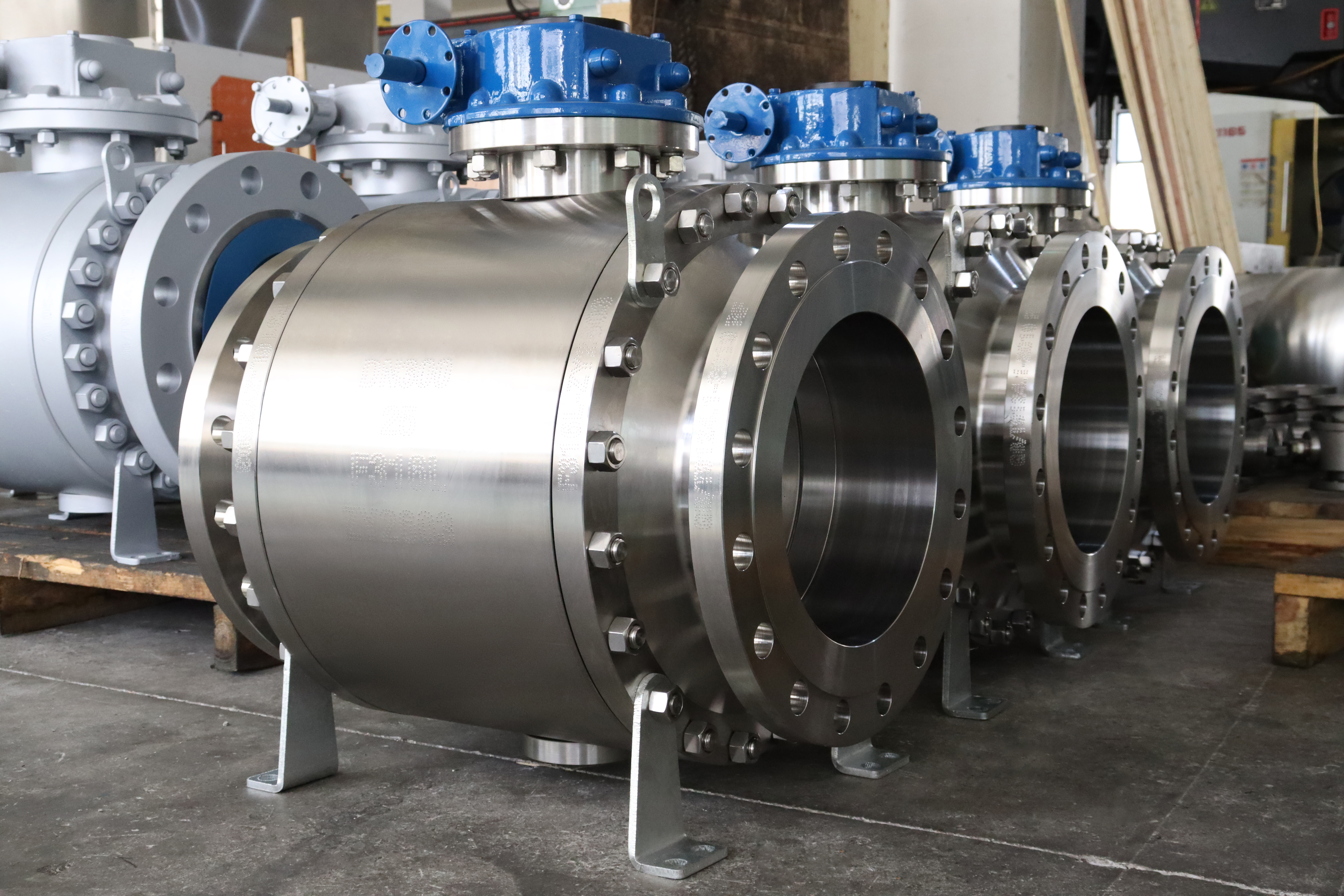
The J-VALVES PN25 three piece forged trunnion ball valve is a DN300, twelve inch, full bore isolation valve with an ASTM A182 F316L body, offered with ends drilled to EN 1092-1 at PN25. The ball is carried between an upper and a lower trunnion, so line pressure reaches the bearings rather than the seat rings, and the body is split into a left body, a centre section and a right body. Operation is through a right angle gearbox with an ISO 5211 pad on the input shaft. The product standard is API 6D.
Twelve inch is where the structure stops being optional. On a floating ball valve the seat ring carries the whole thrust of the line pressure on the ball, and it is also the part that has to slide out of the way when the valve turns. Beyond the sizes where that load can still be turned by hand, the ball has to be supported and the seat has to be left free to do one job only. The customer range puts floating ball valves at one half inch to eight inch, so at DN300 the trunnion is a precondition rather than a feature.
The service it suits follows from those two facts. A twelve inch full bore valve with a forged austenitic body and a European flange pattern turns up on chemical and petrochemical lines that were laid out to EN 1092-1 rather than to ASME, on utility and water headers where a valve of this size is worked from a platform, and on any run where the seats will be changed at some point without cutting the pipe. It is not a cryogenic valve, not a buried valve and not a subsea valve; those three are different products with different bodies.
Design and Construction
The body is three pieces: a left body, a centre section and a right body, held together by two studded joints. Both joints are pressure boundaries rather than locating features, so each carries a spiral wound gasket and its own set of studs, and that set is not the same as the pipe flange studs. The left and right bodies carry one seat pocket each and the pipe flange. The centre section carries the ball, both trunnion bearings, the stem, the bracket and the gearbox.
At six inch and above, the two trunnion bearings sit in bearing blocks that are machined as a pair inside the centre section. That is the structural reason a three piece body holds alignment: the two blocks never separate, because the piece they are machined into is the piece that is never taken apart. The end bodies close the pressure boundary and hold a seat each, and they take no part in locating the ball axis. A two piece body keeps alignment too, but its bearing blocks sit in the body that stays on the line, and the seat is reached through the end that comes off.
At DN300 every part of a strip down is a lifting item. The centre section leaves with the ball, both seats, the stem, the bracket and the gearbox still bolted to it, so the lift is the heaviest assembly in the valve and the one that has to be balanced before it clears the studs. Each end body stays hanging on its pipe flange, which means the pipe support has to carry it while the joint is open. Lifting lugs are provided on the body for this purpose. Slings go round the body, never round the gearbox, the bracket or the stem.
The body carries bolted support feet that stand on the floor or on a structural frame, and those feet take the weight of the valve. A twelve inch forging is not carried by its pipe flanges. In the piping stress model the valve is a concentrated load at the feet rather than a span between two flanges, and the feet are shimmed to the frame before the flange studs are tightened, not after. Doing it the other way round leaves the body joint working against a gap it cannot close.
The bore is full. API 6D Table 1 gives 300.0 mm as the minimum full bore for NPS 12, and this valve is built to that table rather than to the inside diameter of the pipe. A twelve inch Schedule 40 pipe has a slightly larger inside diameter than 300.0 mm, so the valve is a little narrower than the line, which is normal and is not a reduced bore. What it does mean is that a pig is sized on the valve bore, because the valve is the narrowest point in the run.
Each seat is a soft seated assembly with a metal shoulder behind it. In normal service the soft insert does the sealing; if the insert is destroyed, the ball lands on the metal shoulder and the body joint gaskets, which are graphite based, keep the body closed. The seat is energised by a ring of coil springs that give it contact pressure at low line pressure, and by the line pressure as the pressure rises. On a trunnion valve that pressure acts on the seat ring only; it never arrives at the ball as thrust.
The seats are double piston effect as standard, which seals in both directions and lets the cavity be vented to prove each seat on its own. The cost is that a double piston seat cannot relieve itself: with liquid trapped in the cavity and the valve closed, there is no path back to the line. A drain plug sits at the lowest point of the centre section, visible in the photographs under the body, and it drains the cavity. Draining is not relieving. Where liquid can be trapped and warmed, the cavity needs a relief device, or the seats move to single piston effect, which relieves to the low pressure side but seals one way only.
The ends in the photographs are raised face. A ring type joint end is a different end body with a groove machined into the face, not an accessory added to this one, and the ring itself is bought against the groove. The gearbox in the photographs is a right angle unit with a machined pad and a bare square drive on the input side, and no handwheel. Whether the valve ships with a handwheel or with the pad left for an actuator is an order line, and the pad size and the square have to be quoted together.

Material Options
| Component | Standard Material | Optional Upgrade | Service Notes |
|---|---|---|---|
| Body and end pieces | ASTM A182 F316L forging, UNS S31603 | F316 by order | Three pieces, two gasketed joints, both under line pressure |
| Ball | F316L, hard chrome plated or nitrided | F316, or cobalt alloy faced | The grade behind the coating is on the 3.1 certificate |
| Stem | 316L | 17-4 PH, UNS S17400, hardness limited for sour service | Retained by the body, anti blowout to API 6D |
| Seat rings | RPTFE | PEEK, PPL, or metal seated with a cobalt alloy overlay | The seat compound sets the usable temperature |
| Seat springs | Austenitic stainless coil springs | Nickel alloy by order | Contact pressure at low line pressure |
| Stem packing | Flexible graphite | PTFE, or low emission packing to ISO 15848 | Two O rings and a graphite gasket form the barrier |
| Trunnion bearings | 440C with a self lubricating liner | Nickel alloy, UNS N06625 | Carries the ball thrust, so the seat does not |
| Body joint gaskets | Spiral wound, stainless and graphite | PTFE filled where the medium allows | One set per joint, replaced at every opening |
| Gearbox | Right angle, cast housing | Bevel or worm, by order | Input pad to ISO 5211, handwheel as an option |
The L in F316L is a carbon limit, not a strength grade. A182 F316L holds carbon at 0.03 percent or below, which is what stops chromium carbide forming at the grain boundaries after welding, and that is the whole of the argument for it. On this valve the ends are flanged, so the body is not welded in service; the welding argument is therefore worth nothing here unless the body is to be built up, overlaid or repaired by welding later. What does justify the L is the medium: urea, nitric acid and a few others ask for the low carbon grade on their own account.
F316 and F316L sit in the same material group in ASME B16.34 and read the same allowable stress line, so the L does not buy a higher rating. It buys a lower minimum yield, which the wall thickness calculation has to pay for, and on a thin wall that payment is visible. The rating itself does not come from B16.34 at all here: API 6D sends PN class valves to the EN 1092-1 material group table for pressure and temperature, and that is where the curve on the drawing comes from.
A182 covers forgings, and the cast equivalent of the same alloy is A351 CF3M. The two are not interchangeable on a certificate. A forging is bought for soundness, because a large forging has no shrink cavity and can be ultrasonic tested, while a casting is bought for shape and is examined by radiography or penetrant instead. The 3.1 certificate for an A182 forging reports chemistry and tensile results from the test piece and does not include ultrasonic inspection, which is a supplementary requirement under ASTM A388 and has to be written into the purchase order.
The ball, the stem and the seat rings are inside the body in every photograph, and no photograph of a finished valve will ever show their grade. A data sheet can say F316L ball, F316L stem and a cobalt alloy overlay on a metal seat option, but what the valve actually contains is written on the EN 10204 3.1 certificate against the heat number stamped on the body. A purchaser who needs a wrought ball, or a stem in 17-4 PH, writes it on the order. A page cannot promise it on his behalf.
Technical Specifications
| Item | Value |
|---|---|
| Nominal size | DN300, 12 inch |
| Pressure class | PN25 to EN 1092-1, 25 bar nominal reference |
| Class cross reference | Class 150 is recorded as PN 20 in API 6D clause 7.2, not PN 25 |
| End connection | Flanged, raised face |
| Flange drilling | EN 1092-1 PN25 DN300: 485 mm outside diameter, 430 mm bolt circle, 16 holes of 30 mm for M27 studs |
| Body construction | Three piece: left body, centre section, right body |
| Body material | ASTM A182 F316L forging, UNS S31603 |
| Bore | Full bore, 300.0 mm minimum to API 6D Table 1 |
| Ball | F316L, hard chrome plated or nitrided |
| Stem | 316L, or 17-4 PH by order |
| Seat | RPTFE, PEEK or PPL; metal seated option |
| Seat arrangement | Double piston effect standard, single piston effect by order |
| Face to face | EN 558 ball valve table, series stated on the drawing |
| Design standard | ASME B16.34 wall thickness, API 6D product standard |
| Test standard | API 598, shell 1.5 times and seat 1.1 times |
| Fire safe | API 607, identical in method to ISO 10497 |
| Operation | Right angle gearbox, ISO 5211 input pad |
| Temperature | Set by the seat compound, not by the shell range |
| Certificate | EN 10204 3.1, heat number matched to the body marking |
Pressure class on this valve is PN25, and that is a European class rather than an ASME one. EN 1092-1 carries PN25 as a real step among 2.5, 6, 10, 16, 25, 40, 63, 100, 160, 250, 320 and 400, with 25 bar as the nominal reference, and a valve marked PN25 is a valve whose rating is read out of that standard at the working temperature. The rating is not 25 bar at every temperature, and it is not the ASME Class 150 number at any temperature.
The flange on this valve is the EN 1092-1 PN25 pattern for DN300: 485 mm outside diameter, a 430 mm bolt circle, sixteen holes of 30 mm drilled for M27 studs, raised face. Those numbers are on the drawing and on the certificate, and they are the ones a buyer should measure. The outside diameter on its own does not identify a flange, which is the point the next section makes at length.
Face to face is not taken from ASME B16.10 here. B16.10 is the ASME table for ASME classes, and this valve does not carry an ASME class; the length comes from the EN 558 ball valve table, which is arranged in series, and the series is what has to be quoted. Two valves of the same size and the same pressure class can differ in length because they belong to different series, so a replacement order that gives only the size will produce a valve that does not fit the gap.
Standards and Compliance
| Requirement | Standard | What J-VALVES Supplies |
|---|---|---|
| Pressure rating at temperature | EN 1092-1 material group table, to the rule in API 6D clause 7.2 | Rating curve issued with the general arrangement drawing |
| Wall thickness | ASME B16.34 | Calculated thickness shown on the drawing |
| Product design | API 6D | Valve built, marked and documented to API 6D |
| Pressure test | API 598 | Shell at 1.5 times and seat at 1.1 times, record per valve |
| Fire test | API 607, identical in method to ISO 10497 | Certificate covering the size and class range |
| Face to face | EN 558, ball valve table | Series and dimension stated on the drawing |
| Material certificate | EN 10204 3.1 | Heat number matched to the body marking |
| Anti static | API 6D | Resistance across ball, stem and body measured and recorded |
API 6D clause 7.2 does two things at once. It lists seven pressure designations, PN 20, 50, 64, 100, 150, 250 and 420, against Class 150, 300, 400, 600, 900, 1500 and 2500. It also states that pressure temperature ratings for Class designated valves come from ASME B16.34 while those for PN designated valves come from EN 1092-1. Two consequences follow. Class 150 is PN 20, not PN 25. And a PN25 valve is rated out of the European table, not out of B16.34.
The original page prints the pressure class as 150LB (PN25), which joins two different things with an equals sign. Class 150 is recorded as PN 20 in API 6D, and PN 25 is a separate step in EN 1092-1 with no ASME class opposite it. At DN300 the two flanges are almost the same shape, 485 mm against 482.6 mm outside diameter and a 430 mm bolt circle against 431.8 mm, and they are not the same flange, because one is drilled for sixteen M27 studs and the other for twelve holes of 25.4 mm.
The photographs settle which one this valve is. Counting the holes on the end flange gives sixteen, which is the PN25 pattern for DN300, while the Class 150 pattern at NPS 12 has twelve. So the product name is right and the parameter line is wrong, and what is wrong is the equals sign rather than the size. It matters because a buyer who reads 150LB will order a Class 150 mating flange and then find that four of its studs have nothing to bolt into.
API 608 is often listed beside API 6D on pages of this kind, and on this valve it does not apply. API 608 is written around ASME B16.5 flanges and its flange tables stop at that drilling, so a valve with EN 1092-1 ends sits outside the document; the seat test method differs as well, with API 6D pressurising the cavity and proving both seats at once while API 608 pressurises one side and looks at the other. The standards that govern this valve are ASME B16.34 for wall thickness, API 6D for the product and API 598 for the test.
Fire safe performance is tested to API 607, which is identical in method to ISO 10497. API 6FA is often written alongside those two and should not be: it was written for wellhead and pipeline valves and has since been merged into 607, so listing all three describes one test three times. A fire certificate covers a range of sizes and classes rather than a single valve, so what a buyer should read is the range printed on the certificate, not the marks on the cover.
Manufacturing Process
The body begins as a forged blank rather than a casting. At DN300 the blank is a heavy piece and the forging ratio matters, because it decides how much of the ingot structure is broken down before machining, and it is the reason a large forged body can be trusted where a casting of the same wall would be questioned. The blank is solution annealed, then the flange faces, the bore, the seat pockets and the trunnion bores are machined in as few settings as the geometry allows.
Where a metal seat is ordered, the seat pocket is overlaid with a cobalt alloy and machined back to the pocket geometry. The overlay is a weld deposit and is finished after welding, because a finished surface cannot survive the process. The ball is ground first and plated or nitrided afterwards, and the order of those two steps is fixed: plating before grinding leaves a bare ring where the seat contacts the ball, which is exactly where the coating was needed.
Austenitic stainless is cleaned after machining rather than before, and the cleaning is aimed at free iron rather than at dirt. Tooling that has cut carbon steel leaves iron on the surface, the iron rusts, and on an insulated line that rust reads as a corroding body. The shop passivates to ASTM A380, and where the project asks for evidence, runs a ferroxyl test on the finished surfaces and files the result with the certificate.
Assembly is where the two body joints are made up, and both are torqued in a crossing pattern to a figure that goes on the traveller. The valve is then tested as a complete unit, because both joints are pressure boundaries and a joint that is not tested is a joint that will be found later. After test the bore is dried, the ends are capped, and the body marking is checked against the certificate before packing.

Quality Control and Testing
| Step | What Is Checked | Standard or Acceptance |
|---|---|---|
| 1 | Incoming forging and certificate | A182 F316L, EN 10204 3.1, heat number against the marking |
| 2 | Alloy identification on the body | XRF on every body; carbon read from the certificate, not the gun |
| 3 | Wall thickness | ASME B16.34 calculated thickness, measured at the recorded points |
| 4 | Flange drilling | EN 1092-1 PN25 DN300, 16 holes and bolt circle on the drawing |
| 5 | Bore through the port | Gauge passed, result written on the test record |
| 6 | Shell test | API 598, 1.5 times the rating, no leakage |
| 7 | Seat test, both directions | API 598, 1.1 times the rating, recorded per seat |
| 8 | Gearbox operation and torque | Turns recorded, torque measured on the built valve |
| 9 | Surface and marking | Passivation to ASTM A380, marking matched to the certificate |
Portable X ray fluorescence is used on every body, and it is good at what it does: it separates an austenitic stainless from a duplex or a nickel alloy in seconds, and it reads molybdenum well enough to tell a 316 from a 304. What it cannot see is carbon, and carbon is the line between 316 and 316L. The gun proves the family and the certificate proves the grade, so a supplier who offers XRF as proof of F316L is offering half a proof.
Because the valve is sold as full bore, and because a twelve inch full bore valve and a twelve inch reduced bore valve share the same flanges, the same face to face and the same outside profile, the only proof that the right valve is in the crate is a gauge through the port. That measurement belongs on the test record. Without it, the difference between the two valves stays invisible until the pig arrives at the trap.
The documents that travel with the valve are the 3.1 certificate with the heat number matched to the body marking, the pressure test record with shell and seat results for that valve, the general arrangement drawing with the EN 558 series and the flange drilling, and the fire certificate where one was ordered. Torque and weight figures are measured on the built valve and issued on the same drawing rather than printed on a page, because both change with the seat compound and the differential.

Applications and Industry Service
The valve is built for isolation on lines designed to the European flange system. That is a real distinction rather than a marketing one: a plant laid out to EN 1092-1 has PN25 pipe flanges with sixteen holes at DN300, and a valve drilled to ASME will not go in without adaptors. Chemical and petrochemical plants built by European contractors, utility water headers, and process lines that carry a twelve inch main through a battery of equipment are the usual places it turns up.
Three services should be excluded at the enquiry stage rather than at the drawing stage. Cryogenic duty below the range of the seat compound is one, and it needs a different body, a different extension and a different test. Buried installation is another, because this valve has no stem extension and its cavity drain sits at the lowest point of the body where a buried valve cannot reach it. Subsea is the third: the pressure class and the flange pattern here are onshore patterns.
The site carries other PN25 trunnion valves at smaller sizes and other twelve inch trunnion valves built to ASME classes. The division is deliberate. The small PN25 pages take their own sizes, this page takes DN300 at PN25, and the ASME twelve inch page takes the Class 150 and Class 300 enquiry. A buyer who arrives with a Class 150 requirement is a buyer for that page rather than this one, and saying so costs nothing.
Installation, Operation and Maintenance
The valve goes in with its body supported. The feet are shimmed to the frame or the floor and the flange studs are tightened afterwards in a crossing pattern, so the body is never used to pull the pipe into alignment. A twelve inch forging is stiff enough to straighten a pair of flanges that are out of parallel, and it will do it once: after that the body joint is carrying a bending moment it was never designed for.
Operation is through the gearbox. The number of turns from open to closed belongs on the data sheet, because API 6D puts the turns and the torque in an annex that applies only when the purchaser asks for it, and a valve built to the standard can therefore arrive with no operating data at all. A pipe wrench on the input shaft, or an extension bar on a handwheel, is how gearbox shafts get twisted.
What the three piece body gives is access without cutting pipe, not maintenance without depressurising. Both body joints are pressure boundaries, so the line is isolated, the cavity is drained through the plug at the bottom, and only then are the joints broken. What can be done with the valve in service is the upper stem seal, because the stem is retained by the body and the gland can be worked on with the cavity vented.
Replacing a seat is a rigging job at this size. The joints are broken, the centre section is lifted out with the ball and both seats inside it, the gaskets and studs are replaced with a new set, and the assembly goes back with both joints torqued in a crossing pattern. The studs for the body joint are not the pipe flange studs and do not come out of the same box, which makes them the spare that gets forgotten.
How to Specify and Order
An enquiry for this valve has to settle six things before a drawing can be made: the size, the pressure class and flange standard taken as one decision rather than two, the body grade, the seat compound, the operation, and the face to face series. The first of those is the one that goes wrong, because a request for a twelve inch PN25 valve and a request for a twelve inch 150LB valve read alike and are not the same purchase.
Torque, weight, flow coefficient and face to face dimensions are not printed on this page, and the reason is not that they are unknown. Each depends on the seat compound fitted, the differential the valve sees, the temperature and the safety factor in the purchaser's own specification, so a figure quoted before those are fixed would belong to a different valve. They are measured on the built valve and issued with the general arrangement drawing.
The documents that close the order are the 3.1 certificate, the pressure test record, the general arrangement drawing and the fire certificate where it was ordered. On receipt, the body marking is checked against the certificate, the flange drilling is measured against the EN 1092-1 table for PN25 at DN300 rather than against the outside diameter, and a gauge is passed through the port. Those three checks catch most of what goes wrong between an order and a crate.
FAQ
Q: Is PN25 the same as Class 150?
A: No, and the two are joined by an equals sign on many data sheets by mistake. API 6D lists seven pressure designations in clause 7.2, and Class 150 is PN 20 among them, not PN 25. PN 25 is a separate step in EN 1092-1, with no ASME class opposite it. At DN300 the two flanges look almost the same, 485 mm against 482.6 mm outside diameter and a 430 mm bolt circle against 431.8 mm, but one is drilled for sixteen M27 studs and the other for twelve holes of 25.4 mm, so neither will take the other's bolts. The valve on this page has sixteen holes in the end flange, which is the PN25 pattern.
Q: Why is the body three piece at DN300 rather than two piece?
A: Because of what has to move when the seats are replaced, and how heavy it is. In a three piece body the centre section comes out along the pipe axis with the ball, both seats and both bearing blocks still inside it, while the end bodies stay bolted to the line, so nothing is cut and no pipe flange is broken. The centre section at this size is a lifting item, and so is each end body, which hangs on its pipe flange with the support carrying it while the joint is open. The cost of the pattern is a second gasketed joint under line pressure.
Q: Is the bore really full bore, and can the line be pigged?
A: The bore is full to API 6D Table 1, which gives 300.0 mm as the minimum full bore for NPS 12, and the valve is built to that table rather than to the inside diameter of the pipe. A twelve inch Schedule 40 pipe is slightly wider inside than 300.0 mm, so the valve is a little narrower than the line, which is normal and is not a reduced bore. For pigging this matters in one direction only: the pig is sized on the valve bore, because the valve is the narrowest point in the run.
Q: What does the L in F316L buy on a flanged valve?
A: Less than the catalogue implies. The L is a carbon limit of 0.03 percent, and its purpose is to stop chromium carbide forming at the grain boundaries after welding. This valve has flanged ends, so the body is not welded in service and the welding argument does not apply unless the body is later built up or repaired by welding. What does justify the L is the medium, since urea, nitric acid and a few other services ask for the low carbon grade on their own account. F316 and F316L read the same allowable stress line in ASME B16.34, so the L never buys a higher rating.
Q: Can the seats be changed without cutting the pipe, and can it be done under pressure?
A: Without cutting the pipe, yes. Under pressure, no. Both body joints are pressure boundaries, so the line is isolated, the cavity is drained through the plug at the lowest point of the body, and only then are the joints broken and the centre section lifted out. What can be worked on with the valve in service is the upper stem seal, because the stem is retained by the body and the gland can be reached with the cavity vented. Nothing on the body joints, and nothing in the seat pockets, is accessible under pressure.
Q: Why are there no torque, weight or face to face figures on this page?
A: Because each of them depends on a choice that has not been made yet. Torque follows the seat compound, the differential, the temperature and the safety factor in the purchaser's own specification; weight follows the trim and the end pattern; the face to face dimension follows the EN 558 series, and two valves of the same size and class can differ in length because they belong to different series. All of them are measured on the built valve and issued with the signed general arrangement drawing, which is the document a purchaser can actually hold a supplier to.


Hot Products


News
Ball Valves in A Kraft Pulp Mill: Black Liquor, Green Liquor And The Cost of Choosing The Alloy by Habit
White liquor at pH 14 cracks carbon steel welds, black liquor sets solid below 100 C, green liquor dregs grind seats: alloy choice and torque in a kraft mill.
Read More
Slug Flow And Ball Valves: What Actually Arrives At The Seat
A slug is liquid mass with momentum, not a pressure spike. What changes at the seat, in the cavity and at the actuator when liquid reaches a ball valve.
Read More
Ball Valves in Direct Lithium Extraction: PH 1 Eluate, Gypsum Scale And 438,000 Cycles in Twenty-Five Years
Direct lithium extraction swings valves from pH 1 eluate to pH 12 caustic, 48 column switches a day and gypsum scale. Materials, seats and torque.
Read More
Ball Valves in Geothermal Brine: Silica Scale, Chloride Cracking And The Cooling Trap
Why geothermal brine destroys ball valves: retrograde silica scale, calcite at the flash point, chloride cracking above 60 C and the 250 C seat limit.
Read More