


CHINA J-VALVES Offers Various High-quality I ndustrial Ball Valves
J-VALVES, a distinguished professional ball valve manufacturer rooted in China, takes pride in its extensive product portfolio. Our offerings span a wide range, including trunnion-mounted ball valves, floating ball valves, high-temperature ball valves, high-pressure ball valves, metal-sealed ball valves, ultra-low temperature ball valves, DBB ball valves, Three-way And Four-way Ball Valve, and fully welded ball valves. Each product is a testament to our commitment to precision engineering and reliable performance. Meticulously crafted, they are designed to not only meet but exceed the most stringent industrial demands, ensuring stable operation even under extreme conditions. This enables us to provide our clients with high-value services and makes our valves widely sought-after in industries.
Product Category
Contact Us

Pressure Class: ASME Class 150 to 900 / PN20 to PN150
Service Temperature: -50°C to -196°C
Body Construction: Three-piece, two bolted body joints with metal stop
Body Material: CF8M, CF3M, F316, F304, A350 LF2
Ball: F316 or CF8M, hard chrome or ENP plated, trunnion mounted
Seat: Spring loaded PCTFE, self-relieving; PEEK or metal on request
Stem: F316 extended, blowout proof, anti-static
Packing: Flexible graphite with graphite lantern ring
Body Gasket: 316L spiral wound with graphite filler, captured in groove
Bolting: A320 L7 / L7M with Belleville washers
End Connection: Butt weld ASME B16.25, socket weld, or flanged RF / RTJ
Design Standard: API 6D, ASME B16.34, BS 6364, ISO 28921-1
Test: API 598 shell and seat, BS 6364 cryogenic sequence, helium leak
Operation: Lever, gear, pneumatic or electric
-
DQ367F
-
J-VALVES

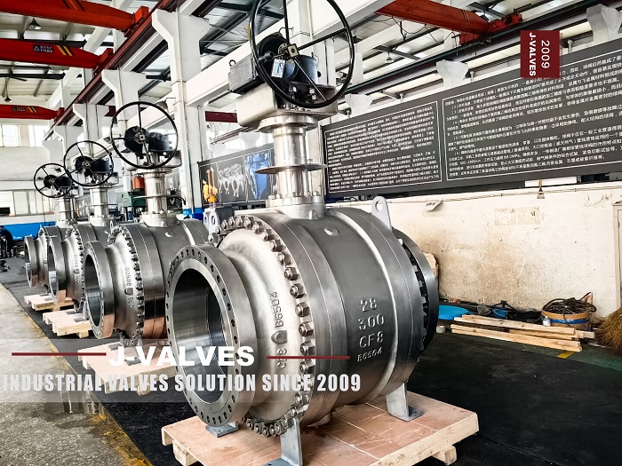
A three-piece cryogenic trunnion ball valve is a quarter-turn isolation valve for -50°C to -196°C service in which the ball is carried on trunnion bearings at both ends and the body is split into two end pieces and a centre section, so the centre section can be unbolted and lifted out while both ends stay welded to the line. It exists because two requirements in cold service pull against each other: cryogenic piping is welded because every flange is a leak path and a break in the insulation, and welded piping cannot be opened for repair. The three-piece body keeps the weld and restores access to the seat.
J-VALVES builds this pattern from 2 inch to 24 inch in ASME Class 150 to 900, in CF8M, CF3M and forged F316, with butt weld or socket weld ends on the two end pieces and spring loaded PCTFE seats throughout. The buyers are air separation packagers, LNG send-out terminals and liquid storage operators who have a small number of large cold valves and no way to cut a line out of a cold box for maintenance. This page is deliberately about the body joint rather than about cryogenic theory: temperature bands, seat materials and the BS 6364 test sequence are set out on the cryogenic ball valve page, and repeating them here would only make two pages compete for the same query.
Why Cryogenic Lines Are Welded in the First Place
A flanged joint in cold service fails for reasons that have nothing to do with gasket quality. The joint is a stack of two flange faces, a gasket and a set of studs, and each part contracts by a different amount between 20°C and -162°C. The studs, being slim, cool faster than the flanges and lose preload first. The gasket takes a compression set on the first cool-down and does not spring back on warm-up. After three or four thermal cycles the joint that passed a 1.5 times shell test at ambient will weep, and nobody can retighten it because it sits under 200 mm of insulation or inside a cold box.
There is a second reason, and it is the one operators usually mention: insulation. A flange pair is a lump of metal twice the diameter of the pipe with a gap in the middle. Insulation has to be cut around it, the vapour barrier has to be sealed to two separate surfaces, and that detail is where ice forms. A butt weld is a smooth 30 mm band that can be wrapped and vapour sealed in one pass. This is why an LNG specification will call for butt weld ends on every isolation valve above 2 inch and simply refuse flanged valves inside the cold envelope.
Why a Fully Welded Body Is Not Automatically the Answer
The fully welded body is the correct answer for buried lines, offshore decks and anything that will never be opened. It has no body joint at all, so there is nothing to relax, and the only dynamic seal is the stem packing. For a 30 inch gas transmission valve that will run for twenty years without maintenance, it is the right choice and it is cheaper than a three-piece body at that size.
The seat, however, is a wear part. A soft seated cryogenic valve has a PCTFE seat that is expected to be replaced at least once in a plant life, and a metal seated valve has a lapped surface that is expected to be touched up. A fully welded body cannot be opened, so replacing a seat means cutting the valve out of the line. On a 4 inch liquid nitrogen branch that is a day of work with a portable saw and a welder. On a 20 inch LNG send-out header it is a shutdown, a crane and a re-certification of the weld, and the cost of that event is far more than the price difference between the two body styles. The three-piece trunnion body is bought for that scenario, not for the first ten years of service but for the one day somebody has to open it.
Three Pieces, Two Joints, and What Each Joint Has to Do
The two body joints are the engineering content of this valve. Each one has to carry the full shell pressure, hold a helium-tight seal through repeated thermal cycling, and be re-makeable in the field by a fitter with a torque wrench. Four details decide whether it does.
A captured gasket in a machined groove. A flat gasket between two flat faces relies on bolt preload alone, and preload is exactly what cold service takes away. A spiral wound 316L and graphite gasket sitting in a groove on the centre section keeps its position during assembly and cannot be extruded outward when the flange faces rotate as they cool.
A metal-to-metal stop behind the gasket. The two body faces come together on a machined shoulder before the gasket is fully compressed. Bolt torque therefore cannot crush the gasket, and a fitter who over-torques the joint damages nothing but his own arm. The stop also fixes the gasket compression at a known value, which is what makes a field re-make repeatable.
Bolting that keeps its preload. Studs are A320 L7 or L7M, impact tested at the design temperature, not A193 B7 which is an ambient grade. Belleville washers under the nuts store enough travel to follow the contraction of the joint stack; without them a joint that was correct at ambient is loose at -100°C.
A relief path for the body cavity. This is not a joint detail, but it decides whether the joint survives. Liquid trapped between the two closed seats warms up, boils and expands several hundred times in volume. If the seat cannot lift to vent into the line, the pressure finds the weakest item in the assembly, and on this valve that is the body joint or the centre section wall.
In practice the second and third items are what separate a valve that works from one that weeps. A joint with a metal stop but plain studs will lose preload. A joint with Belleville washers but no stop is at the mercy of whoever assembled it. Both are invisible from the outside, which is why the joint drawing should be part of the submittal and not an internal document.
Why the Ball Is on Trunnions at This Size
A floating ball is held against the downstream seat by line pressure. That is elegant at 1 inch and 20 bar; it is unworkable at 12 inch and 100 bar. The axial thrust on the ball is line pressure times the bore area, and for a 12 inch Class 600 valve at 102 bar that is roughly 740 kN, or 75 tonnes, all of it landing on a seat ring and a stem. No practical stem carries that and no seat survives it.
A trunnion mounted ball sits on two bearings fixed to the body. Line pressure still acts on the ball, but the load goes into the trunnions and the body ribs rather than into the seat, and the seat is loaded by springs to a value chosen by the designer. Two consequences matter in cold service. First, the seat load does not change when the line pressure changes, so the sealing stress stays in the narrow band where PCTFE seals without being crushed. Second, the torque becomes predictable, because it is a function of seat interference and bearing friction rather than of pressure thrust, which is what allows an actuator to be sized from a catalogue figure instead of a test.
The trade is that a trunnion valve needs a cavity relief arrangement and a more complex seat assembly, and it is heavier. Below 4 inch and below Class 300, a three-piece floating valve is cheaper and perfectly adequate; the trunnion pattern earns its cost from about 6 inch upward and from Class 600 upward at any size.
Body Materials and the Temperature They Actually Allow
Austenitic stainless is the default because it has no ductile-to-brittle transition between 20°C and -196°C. Carbon and low alloy steels do have one, which is why their minimum temperature is a hard number rather than a recommendation.
Grade | Specification | Minimum service temperature | Where it is used on this valve |
|---|---|---|---|
CF8M | ASTM A351 | -196°C | Centre section and end pieces, Class 150-600, the standard choice |
CF3M | ASTM A351 | -196°C | Where the end piece will be welded to the line and carbon pickup matters |
F316 / F316L | ASTM A182 | -196°C | Forged end pieces, Class 900 and above, and sizes over 16 inch |
F304 | ASTM A182 | -196°C | Air separation and liquid nitrogen, where molybdenum is not needed |
A350 LF2 | ASTM A350 | About -46°C | Cold carbon steel service, not LNG, not liquid nitrogen |
A352 LCC | ASTM A352 | About -46°C | Large cast carbon bodies for cold service, same limit as LF2 |
The end pieces are the parts that get welded, so they are usually forgings above Class 600 even when the centre section is a casting. A casting can be radiographed and the centre section has no weld prep, so it is the cheaper place to put the complex shape. The end piece has to match the pipe chemistry closely enough for a sound weld, which is why CF3M and F316L appear in welded cryogenic specifications: the low carbon grade resists sensitisation in the heat affected zone.
LF2 is worth a sentence because it is misapplied so often. It is a genuine low temperature carbon steel, impact tested at -46°C, with 250 MPa minimum yield. It is correct for cold carbon steel piping and wrong for LNG at -162°C, where its Charpy shelf has already collapsed. A datasheet that asks for an LF2 body at -162°C is asking for a valve that will fail in a brittle manner, and that is worth raising at quotation stage rather than shipping.
Seat, Cavity and the Self-Relieving Question
The seat is a spring loaded PCTFE ring, and on this valve it is normally self-relieving: when cavity pressure exceeds line pressure by a set margin, the seat lifts off its pocket and vents into the upstream side. Downstream relief is provided by the same mechanism on the other seat. The alternative is a double piston seat, which seals in both directions with line pressure and does not relieve; it is used where the cavity must be positively isolated, and it requires an external relief valve.
For cryogenic duty the self-relieving seat is the default for a reason that has nothing to do with sealing. A cavity full of liquid that cannot vent will crack a body on warm-up, and the crack will start at a bolt hole or a section change. The relief mechanism is therefore a pressure vessel protection device, and a valve ordered without it needs a documented relief path in the piping design. This is one of the questions worth asking a supplier directly: does the seat relieve, in which direction, and at what differential.
Rebuilding the Joint in the Field
The procedure is the justification for the whole design, so it is worth stating plainly, including where it is risky.
Isolate, depressurise and vent the cavity through the drain. Confirm zero pressure at the drain, not at the line gauge.
Warm the valve slowly, at roughly 20 to 30 K per hour, with the line gas or with warm nitrogen. Warming a cryogenic valve quickly is as damaging as cooling it quickly, because the body and the ball expand at different rates and the seat takes the difference.
Purge until the atmosphere at the joint is breathable and the hydrocarbon reading is at the plant limit. A body joint opened with liquid still in the cavity will release a large volume of gas.
Mark the joint orientation, then slacken the studs in a star sequence a half turn at a time. Do not remove one stud completely while the others are tight.
Lift the centre section on the cast lifting lugs or the sling eyes, never on the flange faces or the gasket groove.
Replace the seats, the seat seals and the body gaskets. Gaskets are single use. Studs may be reused if they are within length and have not been over-torqued; the washer stack should be replaced.
Inspect the ball for scoring and measure it for ovality. A scored ball will destroy a new seat within a few cycles, so it is lapped or replaced at this point, not later.
Re-assemble with new gaskets and torque in three passes to the figure on the drawing, then repeat the pass after an hour because the gasket continues to settle.
Leak test at ambient before the valve goes back into service. A cold test is not possible in the field, so the ambient seat test is the only proof available and it should be recorded.
The honest limitation is that a body joint re-made in the field is the least reliable seal on the valve afterwards. If the joint is insulated, a weep will not be visible until the insulation is wet and the cold spot has grown. That is why the joint is designed with a metal stop and a captured gasket rather than as a plain flange, and why the torque figure has to travel with the valve.

Sizes, Classes and Bonnet Length
Size | Typical construction | Class | Notes |
|---|---|---|---|
2 to 4 inch | Three-piece floating, trunnion on request | 150-900 | Below this size the trunnion pattern rarely pays for itself |
6 to 12 inch | Three-piece trunnion, forged or cast ends | 150-900 | The main volume of this pattern, cold box headers and send-out lines |
14 to 24 inch | Three-piece trunnion, forged ends | 150-600 | Joint bolt size and gasket width become the practical limit above Class 600 |
Bonnet length is quoted from body centre to gland face and is set by the insulation, not by a catalogue. A cold box wall with 300 mm of insulation needs a bonnet that clears the wall plus the room for a handle outside it, and the dimension has to be agreed before machining because it changes the stem, the gang and the actuator bracket. The same applies to the drain and vent: they are extended to the outside of the insulation and plugged, and their orientation is fixed at order.

What to Put on the Enquiry
Size, ASME class, design minimum temperature, fluid, end connection and whether the ends are butt weld to ASME B16.25 or socket weld, body material, seat material, whether the seat must be self-relieving, bonnet or stem extension length from body centre to gland face, insulation thickness, whether the valve sits inside a cold box, actuation and fail position, test standard and certification, and quantity. A line class sheet shortens the review more than any amount of prose, and a drawing of the insulation detail removes the most common source of rework on this valve: a bonnet that is 50 mm too short.

Frequently Asked Questions
What is the difference between a three-piece and a top entry cryogenic ball valve?
Both allow the internals to be reached without cutting the line. A three-piece body splits at two joints and the centre section comes out sideways, which suits a valve in a horizontal line with room at the side. A top entry body has a single joint on the bonnet and the ball and seats are withdrawn upward, which suits a valve under a deck or in a dense pipe rack where there is no side access, and it leaves only one joint to re-make rather than two. Three-piece is more common in cryogenic service because the weld ends can be forged and the cast centre section is simple.
Can this valve be repaired without cutting it out of the line?
Yes, that is its purpose. The two end pieces stay welded to the pipe and the centre section, which carries the ball, seats and stem, is unbolted and lifted out. Seats, seals and gaskets are replaced on the bench or in place depending on access. The condition is that the line is isolated, depressurised, warmed slowly and purged, and that the joint is re-made to the drawing torque with new gaskets.
Why are the seats spring loaded on a cryogenic ball valve?
Because the seat material contracts several times more than the stainless pocket that holds it. A seat pressed into place at 20°C loses its interference at -162°C and the sealing stress falls to zero, so a spring or wave washer behind the seat keeps the stress positive across the whole temperature range. The spring also gives the seat the travel it needs to lift and vent cavity pressure.
Which end connection should be used inside a cold box?
Butt weld to ASME B16.25, in almost every case. A flanged joint inside a cold box cannot be retightened, breaks the insulation and vapour barrier, and adds a leak path that will not be visible. Socket weld is acceptable on small bore instrument and vent lines where the pipe is small enough that a full penetration butt weld is impractical.
What testing is done before shipment?
Shell test at 1.5 times the 38°C rating and seat test at 1.1 times, both at ambient, to API 598 or API 6D. Then chill down with liquid nitrogen or cold gas until body thermocouples stabilise, a helium seat test at temperature, torque measurement cold, gland and body joint probe, warm-up and a repeat seat test to prove the seat recovers. Records go out by serial number with an EN 10204 3.1 certificate and the impact results for the heats used.
Hot Products


News
Ball Valves in Geothermal Brine: Silica Scale, Chloride Cracking And The Cooling Trap
Why geothermal brine destroys ball valves: retrograde silica scale, calcite at the flash point, chloride cracking above 60 C and the 250 C seat limit.
Read More
Ball Valve Face To Face Dimensions: Why A Correctly Ordered Replacement Still Does Not Fit
A 6 inch Class 150 ball valve can be 267 or 305 mm face to face and both are compliant. How B16.10, EN 558 and flange drilling decide whether it fits.
Read More
Ball Valve Stem Key And Keyway: What Gives Way First, And What The Handle Cannot Tell You
Between the handle and the ball there are four fits. Which one shears, which one cracks, and how a few degrees of lost motion hides a valve that never seated.
Read More
Ball Valve Datasheet: Six Blocks That Decide Whether Two Quotes Are Comparable
A ball valve datasheet only works when six blocks are fixed: pressure basis, bore, temperature ceiling, test, end connection, operator. How each is written.
Read More