


CHINA J-VALVES Offers Various High-quality I ndustrial Ball Valves
J-VALVES, a distinguished professional ball valve manufacturer rooted in China, takes pride in its extensive product portfolio. Our offerings span a wide range, including trunnion-mounted ball valves, floating ball valves, high-temperature ball valves, high-pressure ball valves, metal-sealed ball valves, ultra-low temperature ball valves, DBB ball valves, Three-way And Four-way Ball Valve, and fully welded ball valves. Each product is a testament to our commitment to precision engineering and reliable performance. Meticulously crafted, they are designed to not only meet but exceed the most stringent industrial demands, ensuring stable operation even under extreme conditions. This enables us to provide our clients with high-value services and makes our valves widely sought-after in industries.
Product Category
Contact Us


-
J-VALVES-Q947F
-
J-VALVES
Overview of the J-VALVES API 607 Three Piece Forged Trunnion Valve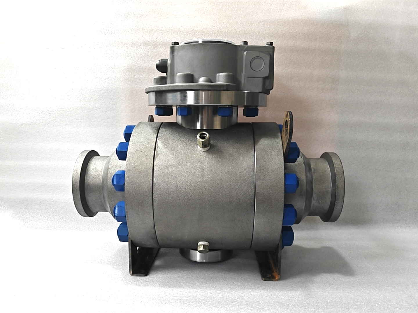
This valve is a three piece forged steel trunnion mounted ball valve qualified to API 607 for fire safe service, built with butt weld ends and fitted with two support feet. The photograph shows what the description usually leaves out: the ends are weld preparations rather than flanges, the body is a centre section with an end body bolted to each side, and the two feet under the body carry it off the pipe axis. It is a valve that becomes part of the pipeline once it is welded in, not a valve that is bolted between two flanges and can be lifted out.
API 607 is a fire test rather than a design code, and the distinction is the reason this page exists. The test puts a valve in a defined flame exposure, lets it cool, and then operates it; what it proves is that after the soft seat has burned away there is still a metal to metal seal that holds, and that the valve can still be turned afterwards. A valve that carries a 607 certificate has been destroyed and rebuilt in a laboratory, and the certificate is specific to the size, the seat arrangement and the materials that were tested.
The third element in the photograph is the pair of support feet. On a welded valve they are not an accessory for lifting. Once the valve is welded into the line it is a section of pipe with a mass and a stiffness, and the feet are what carry that mass and resist the bending that thermal movement and pipe loading put into the body. A welded valve without feet, or with feet that were treated as an afterthought in the foundation design, is a valve whose body flange joints will be asked to do a structural job they were not designed for.
Design and Construction of the Welded Body
The body is a centre section with two end bodies bolted to it, each joint located on a machined spigot and sealed by a spiral wound gasket. The end bodies terminate in butt weld preparations cut to the piping standard, so the valve is joined to the line by welding rather than by bolting. The ball is supported on upper and lower trunnions, and the seats are spring loaded piston seats that seal in both directions, with single or double piston effect available depending on the cavity behaviour the piping design assumes. The end bodies carry the weld preparations, so they are the parts that see the welding heat and the parts that are replaced if a preparation is damaged on site.
The fire safe design is a metal shoulder behind each seat. In normal service the soft seat does the sealing. When the seat burns away, the ball comes into contact with the metal shoulder, and the seal that remains is metal to metal, backed by a graphite body gasket that survives the temperature the fire test imposes. That is what the API 607 test is checking: not that the valve does not get hot, but that after it has been hot there is still a sealing element that is not a polymer.
The support feet are welded or forged onto the body and are positioned so that the valve can sit on a structural support without the pipe carrying its weight. Where they are welded rather than integral, the weld is a structural weld on a pressure containing part and is treated as such: procedure qualified, welder qualified, and examined by magnetic particle or dye penetrant after welding. The feet are drilled for anchor bolts, and the hole pattern is part of the drawing rather than a site decision.
| Component | Standard Material | Optional Upgrade | Service Notes |
|---|---|---|---|
| Centre body and end bodies | ASTM A105 forged carbon steel | A350 LF2 for low temperature, A182 F304 or F316 for corrosive service | Each part forged in one piece and numbered |
| Ball | A351 CF8 with electroless nickel | CF8M, hardfacing for abrasive service | Lapped, carried on both trunnions |
| Trunnion bearings | Bearing blocks bolted into the body | Self lubricating sleeve | Replaceable in line |
| Stem | A276 410 or 420 | 304, 316, 17-4PH | Blowout proof shoulder above the gland |
| Seat | RPTFE | Nylon, PEEK, F316 with hardfacing | Burns away in a fire, the metal shoulder takes over |
| Fire safe element | Metal shoulder behind each seat | Graphite secondary seal | The item the API 607 test actually exercises |
| Body gaskets | Spiral wound, 316 with graphite fill | Ring joint where flanges are fitted | Graphite fill survives the fire test temperature |
| Support feet | Forged or welded to the body | Anchor bolt holes to the drawing | Structural, not a lifting point |
| End connection | Butt weld to ASME B16.25 | Flanged to B16.5 on request | A welded valve becomes part of the line |
| Bolting | A193 B7 with A194 2H nuts | B7M, B16 with A194 7 | Torqued in a crossing pattern in stages |
Material Options and Why the Body Is Forged
A105 is the standard forging grade for a carbon steel body and is right for hydrocarbon service inside the group 1.1 temperature range. A350 LF2 is the low temperature alternative, chosen where the design temperature goes below the impact grade of A105; the two are visually identical and are distinguished by the certificate and by the impact test records, not by the marking alone. A182 F304 and F316 are the stainless options, chosen where the medium attacks carbon steel or where the line has to be cleaned. Where the line is insulated, the specification sometimes asks for a body material that matches the pipe rather than the medium, which is a decision about welding rather than about corrosion.
Forging rather than casting is the normal choice for a valve that will be welded into a line. A welded joint puts heat into the body end, and a casting with shrinkage porosity near the weld preparation will show it as a defect after the weld is made, at which point the valve is already in the line and the repair is a field repair. A forging has no shrinkage porosity to find and can be examined ultrasonically before machining, which is why the weld end specification usually goes with a forged body.
The trim is specified against the fire requirement as well as the process. A soft seat is what makes the valve tight in normal service and is what burns in a fire, so the seat compound and the metal shoulder behind it are a pair rather than two separate choices. Where the valve is also required to be tight after the fire, the leakage that is accepted after the test is a number in the standard and should be quoted rather than assumed.
Technical Specifications
This page describes a pattern rather than a single valve, so the table states a range where a single size page would state a number. The size and class are quoted per order, and what does not change across the range is the arrangement: three piece body, trunnion supported ball, piston seats, metal shoulder behind each seat, butt weld ends and two feet. What is also fixed across the range is the way the valve is joined to the line, which is by welding at both ends.
The two rows that matter most on this pattern are the weld end row and the fire test row. The weld end is cut to the piping standard rather than to a generic bevel, because the fit up gap at the root is set by the preparation and there is no flange to absorb the error. The fire test row names the document rather than the property, because fire safe is a claim and API 607 is a procedure, and only the procedure can be certified.
A third row deserves attention because it is often missing from a quotation at this stage: the cavity relief row. A welded valve with double piston effect seats has a cavity that does not relieve into the line, so the cavity needs its own relief path or a drain that is operated. On a flanged valve that detail can be corrected later; on a welded one it cannot. A drain valve on the cavity is not the same thing as a relief path, and the drawings should show which one is fitted.
| Item | Value |
|---|---|
| Product type | Three piece trunnion mounted ball valve, fire safe, butt weld ends |
| Size range | 2 to 36 inch on this pattern, quoted per size |
| Pressure class | Class 150 to 2500, quoted per class |
| Rating basis | ASME B16.34 for the body material group ordered |
| Body material | ASTM A105 forged carbon steel, with LF2, F304 or F316 as options |
| End connection | Butt weld to ASME B16.25, or flanged to ASME B16.5 on request |
| Weld end note | Weld preparation geometry is cut to the piping standard, not to a generic bevel |
| Support feet | Two feet, forged or welded, drilled to the drawing |
| Trunnion support | Bearing blocks bolted into the body |
| Seat design | Single or double piston effect, declared on the drawing |
| Cavity relief | Self relieving on single piston effect seats only |
| Fire safe element | Metal shoulder behind each seat, graphite secondary seal |
| Fire test standard | API 607, with ISO 10497 as the international equivalent |
| Fire test note | API 6FA is the fire test written for API 6D valves, and is a different document from 607 |
| Pressure test | API 598, with API 6D cavity test where 6D is specified |
| Stem retention | Blowout proof shoulder above the gland |
| Anti static | Stem to body and body to ball |
| Operator | Lever, worm gear, or actuator on a mounting pad |
| Certification | EN 10204 3.1, with the fire test certificate against the tested configuration |
Standards and Compliance
API 607 is the fire test most often named on a quotation for this class of valve, and it is worth being precise about what it is. It is a test procedure: a defined flame exposure, a cooling period, and then an operating cycle, with acceptance criteria for external leakage and for the leakage past the seat after the fire. It says nothing about how the valve is designed or how the body is dimensioned; those come from ASME B16.34 and, where the valve is a pipeline valve, from API 6D.
API 6FA is a separate document with a similar purpose, written for valves within the scope of API 6D. Both are fire tests, both involve flame exposure and a post fire operating cycle, and a valve can be qualified to one without being qualified to the other. When a specification asks for fire safe without naming the standard, the question to ask is which document the end user's specification actually cites, because the certificate has to name the same one.
ISO 10497 is the international equivalent of the fire test and is what most non American specifications cite, often alongside API 607 so that either certificate satisfies the requirement. What does not exist is a single fire certificate that covers all three, and a fire certificate that does not name the size, the seat arrangement and the materials tested does not cover the valve that is being shipped. A specification that cites 607 and 10497 together is asking for either certificate, which is common practice, and a supplier who can only offer one of them should say so before the order rather than after.
| Requirement | Standard | What J-VALVES Supplies |
|---|---|---|
| Body rating | ASME B16.34, material group of the grade ordered | Rated pressure at the design temperature from the group table |
| Weld end geometry | ASME B16.25 | Weld preparation cut and checked against the standard, dimensions recorded |
| Fire test | API 607 or ISO 10497 | Certificate naming the size, seat arrangement and materials tested |
| Fire test, alternative | API 6FA where the specification cites 6D | Certificate against the cited document, not a substitute |
| Pressure test | API 598 | Shell and seat test records, both seats, both directions |
| Cavity test, where 6D is specified | API 6D | Cavity test record in addition to the shell and seat records |
| Material certification | EN 10204 3.1 | Certificate with the forging number on each body part |
| Structural welds on the body | Qualified procedure and welder | Weld records, with magnetic particle or penetrant examination |
Manufacturing Process
The three body parts are forged separately and identified by their own numbers, then normalized where the order calls for it. The weld preparations on the end bodies are cut after the joint faces are machined, so that the end preparation is square to the bore and not square to a rough surface. That matters at a welded joint because the fit up gap is set by the preparation, and a preparation that is out of square closes on one side and gaps on the other when the pipe is brought up to it.
The trunnion bores are line bored so that the upper and lower bearings share an axis, and the seat pockets are cut to hold the seat rings square to the bore. The metal shoulder behind each seat is part of this machining: its face is what the ball contacts after the seat has burned, so it is cut to a controlled surface rather than left as a cast or forged surface. The feet are then fitted or finished, and where they are welded the weld is made before the final pressure test so that the test covers it.
Assembly is done with the ball and seats fitted dry to check the float and the trunnion clearance, then with gaskets and studs torqued in stages. The valve is then pressure tested, and the fire test certificate is issued against the configuration that was actually tested rather than against the size in general. The torque to operate the assembled valve is measured before the operator is fitted, so that a stiff valve is found at the works rather than at the first operating cycle in the plant.

Quality Control and Testing
The shell test is run at one and a half times the rated pressure and the seat test at one and one tenth, both to API 598, with each seat tested in each direction. Where API 6D is specified, the cavity test is added: with the valve closed and the cavity vented, leakage past either seat is measured rather than observed. The test is witnessed for a fire safe order more often than for a standard one, because the same witness session usually covers the dimensional check on the fire related geometry.
The fire test itself is a destructive test and is not run on every valve. It is run on a representative valve of the size, seat arrangement and material combination, and the certificate covers that configuration. What is checked on every valve is the geometry that the fire test depends on: the metal shoulder face, the clearance between the ball and the shoulder, and the graphite content of the body gaskets.
Non destructive examination covers the body forgings by ultrasonic examination and the structural welds on the feet by magnetic particle or penetrant examination. The weld preparations are checked dimensionally against B16.25 and inspected visually for laminations or tears at the bevel, which is where a pipe fitter will first notice that the end is not what the drawing says. The weld preparation is also checked for laminations at the bevel, which is a defect that comes from the plate or the forging rather than from the machining and shows up as a lap when the root is run.
| Step | What Is Checked | Standard or Acceptance |
|---|---|---|
| Incoming forging | Forging number, ultrasonic examination | ASME B16.34 and the order |
| Weld preparation | Geometry, squareness to the bore, bevel condition | ASME B16.25 |
| Metal shoulder | Face condition and clearance to the ball | Works drawing, the geometry the fire test relies on |
| Structural welds on feet | Procedure and welder qualification, examination | Works procedure, magnetic particle or penetrant |
| Shell test | One and a half times rated pressure | API 598 |
| Seat and cavity test | One and one tenth rated pressure, plus cavity test where 6D applies | API 598 and API 6D |
| Fire test | Representative valve of the tested configuration | API 607 or ISO 10497, certificate issued against it |

Applications and Industry Service
A fire safe welded trunnion valve belongs where a leak that becomes a fire is a design case rather than an accident: refinery process units, petrochemical plants, hydrocarbon loading and storage, and offshore topsides where the deck area is small and a pool fire is a credible event. In those locations the specification usually names the fire standard, and the valve is bought against that rather than against a general claim of fire safe construction. In those units the valve is often on a line that is only opened for maintenance, which is why a soft seated valve survives long enough to matter: it is closed for most of its life and worked at a turnaround.
The welded ends put the valve into a different construction sequence from a flanged one. It is installed with the pipe, welded on both sides, and the weld is examined before the line is painted and insulated. That is why the feet and the weld preparation matter so much: there is no second chance to change the end connection after the weld is made, and no flange to take up a misalignment.
The same valve is found on pipeline stations, on compressor and pump manifolds, and on utility headers in plants where the fire case governs the specification. It is not the right choice where the valve has to be removed frequently, because a welded valve is removed by cutting the pipe, and a flanged valve would be the correct pattern for that duty. On a station the valve usually sits inside a fenced area with limited lifting access, which is the practical reason the feet are specified with a hole pattern rather than left to the site to drill.

Installation, Operation and Maintenance
Fit up is the operation that decides whether a welded valve survives its first year. The pipe is brought to the weld preparation with the valve supported on its feet, the gap is set to the welding procedure, and the root is run with the valve in place rather than by welding a spool and forcing it in afterwards. Welding heat is kept away from the seat area where the procedure requires it, and the body is allowed to cool under control rather than quenched. The valve is left closed during welding so that the seat area is not exposed to spatter, and the bore is masked at both ends where the procedure calls for it.
The feet are anchored before the line is pressure tested, and the anchor bolts are shimmed so that the feet carry the valve rather than the pipe carrying the valve while the feet are adjusted. Thermal movement of the line is taken by the piping design, and the feet are not a substitute for an anchor or an expansion loop; where the line grows, the feet have to be able to slide or the body takes the load. Where the line is insulated after testing, the feet have to remain accessible for inspection, which is a detail to settle with the insulation contractor before the valve is wrapped.
Maintenance is by removing an end body, which on a welded valve means the line must be cut and the valve lifted out, unless the end body can be unbolted in place with the line supported. That is the trade for the welded joint: a joint that cannot leak versus a valve that cannot be lifted out without cutting. Where the duty requires frequent inspection, the flanged version of the same body is the correct order.
How to Specify and Order
Six items make the order unambiguous: size, class, body material, end connection, seat and piston effect, and the fire standard with its edition. The fire standard is the item most often left vague, and it is the one that decides which certificate will be issued, so it should be written as a document number rather than as the words fire safe. A seventh is worth adding on a welded valve: the pipe wall thickness or schedule that the end preparation has to match, because the preparation is cut for a wall and not for a nominal size.
State the weld end preparation as ASME B16.25 and state the pipe schedule or wall thickness that the preparation has to match, because a preparation cut for one wall will not fit up to another. State the feet requirement with the anchor hole pattern, since the structural design is done before the valve arrives. Where the pipe is already on site, measure the outside diameter and the wall at the end and put both on the drawing, since a preparation cut for a heavier wall will leave a step inside the bore that the root cannot bridge.
Where the valve is replacing an existing one in a welded line, order against the measured face to face length and the measured pipe outside diameter rather than against the nominal size. J-VALVES quotes from the drawing for the size, the class, the material and the trim ordered, and issues the 3.1 certificate against the forging number that appears on the body and on each end body. The face to face length is the dimension to measure first, because a replacement that is longer by a few millimetres cannot be pulled into a line that has already been cut to length.
FAQ
Q: Is API 607 the same as API 6FA?
A: No. Both are fire test procedures with a flame exposure, a cooling period and a post fire operating cycle, but they are separate documents written for different scopes, and a valve qualified to one is not automatically qualified to the other. The practical question is which document the end user specification cites, because the certificate has to name that one. Where a specification asks for fire safe and names nothing, the answer should be a question rather than an assumption.
Q: What does the fire test actually prove?
A: That after the soft seat has burned away there is still a metal to metal seal between the ball and the shoulder behind the seat, that the body joint still holds with a graphite gasket, and that the valve can still be operated after the fire. It does not prove that the valve stays tight to the same leakage class as when new, and the allowable post fire leakage is a figure in the standard rather than a promise from the supplier.
Q: Are the support feet required?
A: On a welded valve they are effectively required, because the valve becomes part of the pipeline and carries structural load once it is welded in. The feet take the valve mass off the pipe and resist the bending that thermal movement puts into the body, and the anchors are set before the line is pressure tested so that the pipe is never carrying the valve while the feet are adjusted.
Q: Why are the ends butt weld rather than flanged on this valve?
A: Because a welded joint cannot leak to atmosphere, which is the point on a line where a fire case governs the specification. The trade is maintenance: a welded valve is removed by cutting the pipe, while a flanged valve can be unbolted. Where the duty needs frequent access, the same body is ordered with flanges as a different end body rather than as an adapter.
Q: Can the valve be supplied with a fire certificate for my exact size?
A: The fire test is destructive and is run on a representative valve of the size, seat arrangement and material combination, so the certificate covers that configuration rather than every size in the range. What is checked on every valve is the geometry the fire test depends on: the metal shoulder face, its clearance to the ball, and the graphite content of the body gaskets. If a certificate naming your exact size is a contract requirement, say so at enquiry.
Q: What has to be stated on the order beyond size and class?
A: The body material, the end connection with the pipe wall it has to match, the seat type with its piston effect, the fire standard with its edition, the foot and anchor hole pattern, and the operator. The pipe wall thickness is the one most often left out, and a weld preparation cut for a heavier wall leaves a step inside the bore that the root cannot bridge.


Hot Products


News
Ball Valve Condition Monitoring: Which Signals Actually Predict A Failure
Torque signatures, acoustic emission, differential pressure and digital twin residuals: which measurements find a failing ball valve early.
Read More
Ball Valves in SWRO Desalination: The High Pressure Section Where Ordinary Seawater Valves Fail
Why SWRO high pressure valves fail early: recovery arithmetic, crevice temperature, ERD ripple, scale, letdown cavitation and surge.
Read More
Air Test And Water Test For Ball Valves: What Each Medium Can Prove
A ball valve can pass a hydrostatic seat test and still leak gas. Why air and water prove different things, and how to read a bubble, decay or helium test.
Read More
Ball Valve Flange Bolting: Preload, Relaxation And The Fasteners That Decide Leakage
A weeping flange is rarely the gasket. Preload, torque scatter, hardness limits and thermal relaxation decide whether the joint holds at 100 bar and 400 C.
Read More