


CHINA J-VALVES Offers Various High-quality I ndustrial Ball Valves
J-VALVES, a distinguished professional ball valve manufacturer rooted in China, takes pride in its extensive product portfolio. Our offerings span a wide range, including trunnion-mounted ball valves, floating ball valves, high-temperature ball valves, high-pressure ball valves, metal-sealed ball valves, ultra-low temperature ball valves, DBB ball valves, Three-way And Four-way Ball Valve, and fully welded ball valves. Each product is a testament to our commitment to precision engineering and reliable performance. Meticulously crafted, they are designed to not only meet but exceed the most stringent industrial demands, ensuring stable operation even under extreme conditions. This enables us to provide our clients with high-value services and makes our valves widely sought-after in industries.
Product Category
Contact Us


-
J-VALVES-Q347F
-
J-VALVES
Overview of the J-VALVES 6 Inch Class 1500 A105N Trunnion Ball Valve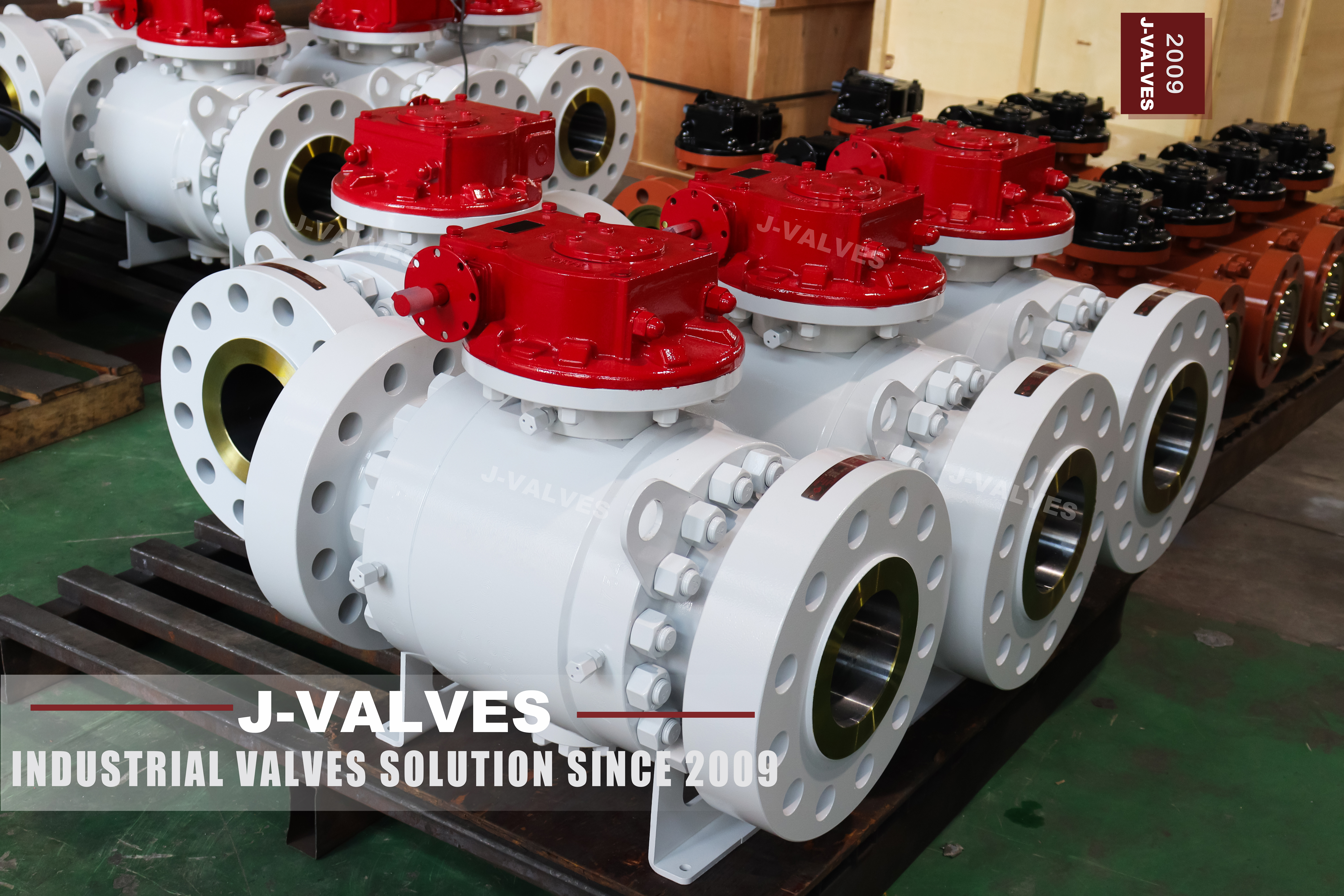
This is a three piece forged carbon steel trunnion mounted ball valve in 6 inch at Class 1500, with raised face or ring joint flanges to ASME B16.5 and a worm gear as the standard operator. The body is forged from ASTM A105N and normalized, the ball is carried on upper and lower trunnions rather than floating, and the seats are spring loaded piston seats that seal in both directions. It is built for high pressure water, oil and gas service where the line is clean and the pressure does not come down.
Class 1500 at 6 inch is the point where three separate facts about the specification become worth stating on one page, because each of them is routinely written wrongly on data sheets for this size. The first is the metric designation: the ISO name for Class 1500 is PN 250, and a sheet that prints PN 260 has printed a number that appears in neither API 6D nor EN 1092-1. The second is the product standard: API 608 stops at Class 600, so a Class 1500 valve cannot carry a 608 compliance statement at any bore. The third is mechanical rather than documentary, and it is the one that decides how the valve is built.
That third fact is the trunnion support. Up to four inch, the upper and lower trunnions are machined as part of the body and run directly in bores cut into it. From six inch upward the trunnions are carried in two separate bearing blocks bolted into the body, because at this size the loads and the bore make an integral trunnion impractical to machine and impossible to replace. A six inch valve is therefore the first size in the range where the bearing blocks are a service item, and that is visible in the drawing before it is visible in the price.
Design and Construction of the Three Piece Trunnion Body
The body is split into a centre body and two end bodies, bolted together with high strength alloy steel studs. The joint faces are machined flat and sealed with spiral wound or ring joint gaskets, and each end body is located on a machined spigot so that the bore is aligned by metal rather than by the studs. Three pieces means two joints, which is one more potential leak path than a two piece body, and at Class 1500 that extra joint has to be justified: it is justified by being able to remove either end body with the valve still in the line, so the ball, the seats and the seals can be replaced without cutting the pipe.
The ball is fixed in position by the trunnions and does not move with pressure. Each seat is pushed against the ball by a set of coil springs and then loaded further by the line pressure acting on the seat piston area, which is the piston effect. In a single piston effect seat the upstream pressure pushes the seat onto the ball while the downstream pressure pulls it away, so the cavity is self relieving; in a double piston effect seat both directions push the seat onto the ball, so the cavity is not self relieving and needs its own relief path. Which of the two is fitted changes the cavity behaviour and has to be stated on the order.
The stem passes through the body neck, is retained against blowout by a shoulder that cannot pass through the gland, and is sealed by a packing set compressed by a gland bolted to the neck. An anti static device connects the stem to the body and the body to the ball, and a metal shoulder behind each seat provides the fire safe seal once the soft seat has burned away. The worm gear is bolted to a mounting pad on the neck, drives the stem through a keyed coupling, and is non reversing so that the valve holds position without a brake.
| Component | Standard Material | Optional Upgrade | Service Notes |
|---|---|---|---|
| Centre body and end bodies | ASTM A105N forged carbon steel, normalized | A350 LF2 for low temperature, A182 F304 or F316 for wet service | Each forging is one piece, no cast or welded body |
| Ball | A351 CF8 with electroless nickel | CF8M, or hardfaced with tungsten carbide | Lapped spherical, supported by both trunnions |
| Trunnion bearings | Two separate bearing blocks from 6 inch upward | Self lubricating sleeve, or alloy bearing | Replaceable without removing the valve from the line |
| Stem | A276 410 or 420 | A276 304, 316, or 17-4PH | Blowout proof shoulder above the gland |
| Seat | RPTFE | Nylon, PEEK, or F316 with hardfacing for metal seating | Single or double piston effect, stated on the order |
| Seat springs | Coil springs behind each seat ring | Heavy duty set for low pressure sealing | Preload only, the piston effect does the work at pressure |
| Packing | PTFE V rings | Flexible graphite for higher temperature | Gland at the body neck, adjustable |
| Body gaskets | Spiral wound, 316 with graphite fill | Ring joint gasket for RTJ flanges | One gasket at each of the two body joints |
| Bolting | A193 B7 with A194 2H nuts | B7M, or B16 with A194 7 for the highest grades | Studs through, torqued in a crossing pattern |
| Body drains | Plug in the cavity low point | Vent and drain valves, one at each end of the cavity | Position fixed by the installation orientation |

Material Options and the Meaning of the N in A105N
A105N is the normalized version of the A105 forging grade. Normalizing heats the forging above its transformation range and cools it in air, which refines the grain and evens out the structure left by forging; the result is a body with better and more consistent impact toughness than the same chemistry left as forged. At Class 1500 in 6 inch the wall is thick, and a thick section is exactly where an unnormalized forging retains a coarse grain and a scatter of toughness values that the mill certificate will not show, which is why the N belongs on the order and not only in the description.
The ball and seat options are where a high pressure valve is usually specified without enough thought. A CF8 ball with electroless nickel is the standard and is right for clean water, oil and gas; hardfacing is specified where the medium carries solids, and it changes the seat as well, because a hardfaced ball running against a soft seat wears the seat rather than the ball. A metal seated valve is chosen for temperature or for fire survival, and it brings a permissible leakage rate with it that has to be agreed rather than assumed. A metal seated valve that has been ordered without that rate agreed is a valve that will fail its first site acceptance test against a number nobody wrote down.
The stem grade deserves a line of its own. A276 410 and 420 are martensitic stainless grades with enough strength for the torque at this size, and 17-4PH is used where the strength requirement is higher still. The stem is the part that sees the full line pressure across its section and the full operating torque at the same time, so substituting a free machining grade to save cost is not a neutral change, and a stem that twists off leaves the valve stuck in whatever position it was in.
Technical Specifications
The rows in this table fall into three groups and they should be read differently. The first group is fixed by the standard and cannot be negotiated: the face to face length, the flange drilling, the minimum body wall, the stem diameter. The second group is a decision the buyer makes and the drawing records: the seat type, the piston effect, the operator, whether NACE applies. The third group is a record of what was actually built, and the two rows on trunnion support and cavity relief belong there, because they describe the internal arrangement rather than a catalogue option.
Two rows need reading together. The metric designation row says PN 250 and the designation note row says why 260 is not used. They are not a duplicate: one states the correct ISO name for the class, the other records that a number in circulation is not a designation at all. Keeping both is what allows a buyer who has been quoted PN 260 to see the correction without losing the search term.
The flange bolting row is there because the bolt count is the first thing a site check will verify and the last thing a data sheet usually states. At NPS 6 Class 1500 the B16.5 table calls for twelve bolts, and a valve delivered with a different count has been drilled to a different table, whatever the class marking on the body says. The same row also fixes the bolt size and the stud length, and the stud length is what decides whether the studs bottom out in a blind hole or stand proud of the nut.
| Item | Value |
|---|---|
| Product type | Three piece trunnion mounted ball valve, piston seats, worm gear operated |
| Nominal size | 6 inch, DN150 |
| Pressure class | ASME Class 1500 |
| Metric designation | PN 250, the designation API 6D clause 7.2 writes against Class 1500 |
| Designation note | PN 260 appears in neither API 6D clause 7.2 nor the EN 1092-1 nominal pressure series |
| Rating basis | ASME B16.34, material group 1.1 for A105N |
| Body material | ASTM A105N forged carbon steel, normalized |
| End connection | Raised face or ring joint flanged to ASME B16.5 Class 1500 |
| Flange bolting | Twelve bolts at NPS 6 Class 1500, to the B16.5 table |
| Face to face | ASME B16.10 for NPS 6 at Class 1500 |
| Bore | Full bore to API 6D Table 1 for NPS 6, reduced bore on request |
| Trunnion support | Two separate bearing blocks, upper and lower |
| Seat design | Single or double piston effect, declared on the drawing |
| Cavity relief | Self relieving on single piston effect seats only |
| Anti blowout stem | Shoulder above the gland, retained by the body neck |
| Anti static | Stem to body and body to ball |
| Fire safe | Metal shoulder behind each seat, API 607 and ISO 10497 |
| Product standard | API 6D |
| Product standard note | API 608 stops at Class 600 and cannot be claimed at Class 1500 |
| Test standards | API 6D and API 598 |
| Certification | EN 10204 3.1 with the forging number on each body part |
| NACE | MR0175 on request, not a default |
| Operator | Worm gear with handwheel and position indicator, non reversing |
Standards and Compliance
ASME B16.34 rates this valve. A105N sits in material group 1.1, and the group 1.1 table at Class 1500 gives the allowable pressure at each temperature; that table is the only place the rated pressure comes from, and it is read rather than calculated from a conversion. The same standard sets the minimum body wall and the stem diameter for the class and bore, which is why a 6 inch Class 1500 body cannot be slimmed down for cost without leaving the standard, and why wall thickness is measured on the finished casting or forging rather than assumed from the class.
API 6D is the product standard, and it is the one this valve is built to. It covers the body joint, the stem retention, the trunnion support, the seat and cavity arrangement, the anti static path, the fire safe design and the pressure test procedure, and it has no class ceiling, which is exactly why it applies at 1500 where API 608 does not. A trunnion valve at this size without a 6D design basis is a valve designed to a catalogue.
API 608 is the document to leave off this page. Its flanged scope is DN15 to DN600 at Class 150, 300 and 600 only, and its threaded scope is DN8 to DN50 at Class 150 to 800; neither reaches Class 1500 at any bore. A data sheet that lists API 608 and API 6D together on a Class 1500 valve is describing a valve that cannot exist, and a buyer who checks the certificate against the sheet will find the gap. The correct pair for this valve is API 6D for design and API 598 for the pressure test, with API 607 or ISO 10497 for the fire qualification.
| Requirement | Standard | What J-VALVES Supplies |
|---|---|---|
| Pressure temperature rating | ASME B16.34, group 1.1, Class 1500 | Rated pressure at the design temperature, taken from the group 1.1 table |
| Body wall and stem size | ASME B16.34 minimum for the class and bore | Wall and stem measured and recorded on the inspection sheet |
| Product design | API 6D | Body joints, trunnion support, seat and cavity design, stem retention |
| Fire safe qualification | API 607 and ISO 10497 | Certificate for the size, seat type and piston effect combination tested |
| Pressure testing | API 6D and API 598 | Shell and seat test records, plus the cavity test API 6D requires |
| Material certification | EN 10204 3.1 | Certificate with the forging number on the centre body and each end body |
| NACE compliance | NACE MR0175 | On request, with the hardness survey on the wetted parts |
Manufacturing Process
The centre body and each end body are forged from separate billets, then normalized before any machining. Forging a body at this size means starting from a billet that is pierced and worked on a press until the grain follows the shape of the wall, which is the property a casting cannot offer: a forged wall has no shrinkage porosity to find later and no repair welds to declare. Each forging is identified by its own number, so the three parts of one valve can be traced separately.
After normalizing the body is rough machined, the joint faces and flange faces are cut, and the part is stress relieved before the finishing cuts. The trunnion bores are then line bored so that the upper and lower bearings share one axis, which is the operation that decides how the ball sits between the seats and how evenly the two seats load. The bearing blocks are machined separately and fitted, and because they are separate parts they can be replaced without touching the body or the piping.
Welding is restricted to the extent the standards allow on a pressure boundary, and any weld on a forging is recorded against the part number rather than left to be discovered. The ball is ground and lapped, hardfaced where specified, and checked for sphericity before assembly. Assembly is done with the ball and seats fitted dry to check the float and the trunnion clearance, then with gaskets and studs torqued in a crossing pattern in stages rather than in one pass, and the torque is recorded on the assembly sheet so that a joint opened in the field can be made up to the same value.

Quality Control and Testing
The shell test is run at one and a half times the rated pressure and the seat test at one and one tenth, both to API 598, and API 6D adds a cavity test that a floating valve does not need: with the valve in the closed position and the cavity vented, no leakage is allowed past either seat into the cavity beyond the permitted amount. On a double piston effect seat the cavity is not self relieving, so the test also confirms that the relief arrangement works.
Non destructive examination on a Class 1500 forging follows the order and the standard in force: ultrasonic examination of the body forgings, magnetic particle examination of the machined surfaces and of any permitted weld repair, and a hardness survey on the wetted parts where NACE has been specified. The examinations are recorded against the forging number rather than against the order, which is what allows the 3.1 certificate to point at a specific part instead of at a batch of forty.
Dimensional inspection covers the flange bolt circle and facing, the face to face length, the bore and the trunnion bore alignment. The flange bolt count is recorded as a number because it is the first thing a site check will count, and the facing type is recorded because an RF valve and an RTJ valve are not interchangeable at the same bolt circle, even though their bolt counts match. Final marking, flange protection and packing follow the same inspection sheet, so that what leaves the works can be checked against what was tested.
| Step | What Is Checked | Standard or Acceptance |
|---|---|---|
| Incoming forging | Forging number, ultrasonic examination of the body | ASME B16.34 and the order |
| Normalizing | Furnace record and cooling method | Works procedure, chart recorded |
| Rough machining and stress relief | Joint face and flange allowance after relief | Works drawing |
| Trunnion boring | Upper and lower bores on one axis | Works drawing, measured |
| Ball preparation | Sphericity, hardfacing thickness where specified | Works procedure |
| Shell test | One and a half times rated pressure | API 598 |
| Seat and cavity test | One and one tenth rated pressure, plus cavity test | API 598 and API 6D |
| Dimensional | Bolt circle, facing, face to face, bore | ASME B16.5, B16.10, API 6D Table 1 |

Applications and Industry Service
Class 1500 at 6 inch belongs to high pressure water injection, high pressure oil and gas gathering, pump discharge and compressor station piping, and to the high pressure side of processes where the line is clean and the pressure stays up. The common factor across those duties is a steady pressure rather than a spike; a valve chosen to survive a surge is chosen on a different basis again, and the difference shows up in the seat design rather than in the body.
It is also used on wellhead and manifold piping on land, and on high pressure test loops. It is not the right valve for a line that carries solids at speed, for a service where the seat has to hold with the cavity full of abrasive, or for a low temperature duty below the impact grade of A105N; those cases need a different body material and a different seat, and the class stays the same while everything else changes.
The reason a trunnion valve rather than a floating one appears at this size is worth stating because it is often stated wrongly. A floating ball at 6 inch and Class 1500 would press on the downstream seat with the full line pressure over the full seat area, which at this bore is a load no soft seat survives and a torque no operator can apply by hand. The trunnion takes that load into the body through the bearings, and the seat only has to seal, which is why the operating torque of a trunnion valve stays low and steady across the pressure range instead of rising with it.

Installation, Operation and Maintenance
Flange make up at this size is a controlled operation. The twelve bolts are tightened in a crossing pattern in at least three stages to the torque the gasket and the stud grade call for, and the flange faces are checked for parallel before the first stage, because a Class 1500 joint with one bolt over tightened will leak at the opposite side and cannot be corrected by adding torque. A ring joint gasket is used once and replaced; it is not reused after a break.
The worm gear is non reversing and self locking, so the valve stays where it is put without a brake, which matters on a valve that may sit half open for years between operations. The position indicator on the gear shows the ball angle, and the mechanical stops limit travel; the handwheel should never be used to force the valve past a stop, because the stop is in the gear and the seat is what gives way. Where a lockout is required, the arrangement is on the gear input, not on the stem.
Maintenance is the reason this valve is three piece. With the line isolated and the cavity drained through the body plugs, either end body can be unbolted and removed, which gives access to the seat, the ball and the trunnion bearing on that side without disturbing the other flange. The bearing blocks are replaceable, which matters because they are the item that degrades first on a valve cycled many times under pressure. The body joints are then made up with new gaskets to the same torque procedure.
How to Specify and Order
Six items make an order unambiguous at this size: the bore and class as numbers, the body material and its condition, the flange type and facing, the seat type together with its piston effect, the operator, and whether NACE is required. The two that cause the most rework are the seat type and the piston effect, because the cavity behaviour follows from them and the cavity behaviour is what the piping design assumed.
State the pressure class as Class 1500 and, if a metric designation is wanted, as PN 250. Do not write PN 260. A supplier who quotes against PN 260 is either converting a rated pressure into a designation or copying a data sheet forward, and either way the number will not appear on any flange in the order. The two designations describe the same class, and only one of them is a designation rather than a conversion.
Where the valve is going into an existing Class 1500 line, order against the flange facing and bolt circle rather than against the class alone, and ask for the trunnion bearing arrangement to be shown on the general arrangement drawing. J-VALVES quotes from the drawing for the size, the material and the trim ordered, and issues the certificate against the forging number that appears on the body and on each end body, so that the three parts of one valve can be traced as one delivery.
FAQ
Q: Is the class 1500 valve PN 250 or PN 260?
A: PN 250. API 6D clause 7.2 lists seven designations against the ASME classes, and the one written against Class 1500 is PN 250; the EN 1092-1 nominal pressure series also has PN 250. PN 260 does not appear in either document, and a quotation written against it has either converted a rated pressure into a designation or copied a sheet forward. The class is the same; only the designation is different.
Q: Can this valve be supplied with an API 608 certificate?
A: No. The flanged scope of API 608 runs from DN15 to DN600 at Class 150, 300 and 600, and its threaded scope from DN8 to DN50 at Class 150 to 800. Neither reaches Class 1500 at any bore, so no 608 compliance statement can be issued for this valve. It is designed and tested to API 6D, with API 598 for the pressure test and API 607 or ISO 10497 for the fire qualification.
Q: What changes at six inch compared with a four inch trunnion valve?
A: The trunnion support. Up to four inch the upper and lower trunnions are machined as part of the body and run in bores cut into it; from six inch upward the trunnions are carried in two separate bearing blocks bolted into the body. The blocks are a replaceable service item, which changes what a rebuild costs after years of cycling, and it is the first thing to look for on the section drawing.
Q: What does the N in A105N mean?
A: Normalized. The forging is heated above its transformation range and cooled in air, which refines the grain and evens out the structure left by forging. At Class 1500 in six inch the wall is thick, and a thick section is where an unnormalized forging keeps a coarse grain and a scatter of toughness that the mill certificate will not show. The N belongs on the order, not only in the description.
Q: Single or double piston effect, which should I order?
A: It depends on what the piping design assumed about the cavity. A single piston effect seat lets the cavity relieve into the line, so trapped pressure escapes on its own; a double piston effect seat seals in both directions and the cavity does not relieve, so it needs its own relief path. Ordering double piston effect without that path traps liquid in the cavity, and the trapped volume loads both seats as it warms.
Q: Is the worm gear included as standard?
A: Yes at this size and class. The gear is non reversing, so the valve holds position without a brake, and it carries a position indicator and mechanical stops. The handwheel should never be used to force the valve past a stop, because the stop is in the gear and the seat is what yields. Lockout, where required, is fitted on the gear input rather than on the stem.


Hot Products


News
Ball Valve Condition Monitoring: Which Signals Actually Predict A Failure
Torque signatures, acoustic emission, differential pressure and digital twin residuals: which measurements find a failing ball valve early.
Read More
Ball Valves in SWRO Desalination: The High Pressure Section Where Ordinary Seawater Valves Fail
Why SWRO high pressure valves fail early: recovery arithmetic, crevice temperature, ERD ripple, scale, letdown cavitation and surge.
Read More
Air Test And Water Test For Ball Valves: What Each Medium Can Prove
A ball valve can pass a hydrostatic seat test and still leak gas. Why air and water prove different things, and how to read a bubble, decay or helium test.
Read More
Ball Valve Flange Bolting: Preload, Relaxation And The Fasteners That Decide Leakage
A weeping flange is rarely the gasket. Preload, torque scatter, hardness limits and thermal relaxation decide whether the joint holds at 100 bar and 400 C.
Read More