


CHINA J-VALVES Offers Various High-quality I ndustrial Ball Valves
J-VALVES, a distinguished professional ball valve manufacturer rooted in China, takes pride in its extensive product portfolio. Our offerings span a wide range, including trunnion-mounted ball valves, floating ball valves, high-temperature ball valves, high-pressure ball valves, metal-sealed ball valves, ultra-low temperature ball valves, DBB ball valves, Three-way And Four-way Ball Valve, and fully welded ball valves. Each product is a testament to our commitment to precision engineering and reliable performance. Meticulously crafted, they are designed to not only meet but exceed the most stringent industrial demands, ensuring stable operation even under extreme conditions. This enables us to provide our clients with high-value services and makes our valves widely sought-after in industries.
Product Category
Contact Us


-
J-VALVES-Q347F
-
J-VALVES
Overview of the J-VALVES 6 Inch Class 600 A105 Trunnion Valve for Turbine Heads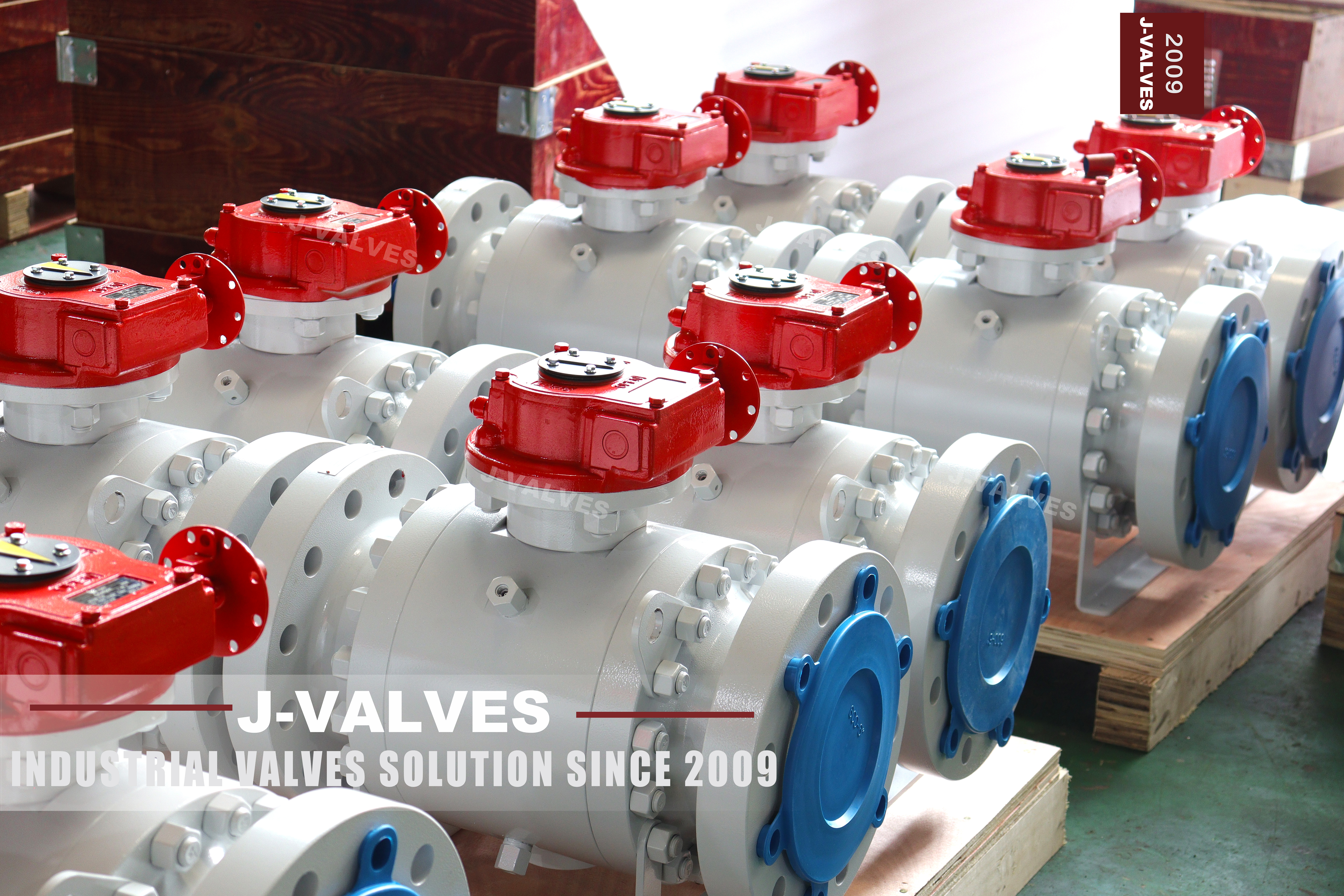
This is a three piece forged carbon steel trunnion mounted ball valve in 6 inch at Class 600, with raised face or ring joint flanges to ASME B16.5 and a worm gear as the standard operator. The gear is the detail to look at in the photograph: a red gearbox on the neck, a handwheel on the input shaft and a mechanical position indicator on the top cover. On a valve in this position the operator is not an accessory, it is the part that decides whether the valve can be worked at all during a short outage window.
Turbine head is the term used at the plant for the piping immediately upstream of the turbine stop valve and the governing valve, and it is a place where a valve is asked for two different things. In normal running it is open and does nothing. During a start it is used to warm the line and to drain it, which means it is worked repeatedly while the line is coming up to temperature, and during a shutdown it is closed to isolate the turbine from the header. A valve that is sized for the pressure but not for that pattern of use will be the one that leaks at the next start.
Class 600 is also the class where the standards question has a different answer from the higher rated pages in this catalogue. At this class a flanged valve falls inside the scope of API 608, because the flanged scope runs to Class 600 and stops there. The same valve at Class 1500 leaves that scope on class alone. Two pages in one catalogue, one class apart, and only one of them can carry a 608 statement.
Design and Construction of the Gear Operated Trunnion Body
The body is a centre section with two end bodies bolted to it, each joint sealed by a spiral wound or ring joint gasket and located on a machined spigot. The ball is held between upper and lower trunnions, so the line pressure is carried into the body through the trunnion bearings rather than through the seats, and the seats are loaded by springs plus the piston effect of the pressure acting on the seat ring. Both joints carry the same gasket type and the same stud grade, and both are machined on the same setup as the centre body, which is why a three piece body at this class can be opened in the field and closed again without losing the bore alignment.
The worm gear is bolted to a pad on the body neck and drives the stem through a keyed coupling. The drive is non reversing, which means the gearbox holds the ball in position without a brake and the valve cannot be crept open or closed by flow pulsation or by vibration in the header. That property matters on a turbine head line, where the flow is unsteady during a start and the valve may sit at a partly open position for a long period while the line warms.
The gear carries a mechanical position indicator coupled to the stem, so the ball angle can be read from outside without removing anything, and mechanical stops limit travel to a quarter turn. The stem is retained against blowout by a shoulder that cannot pass through the gland, an anti static path connects the stem to the body and the ball, and a metal shoulder behind each seat gives the fire safe seal once the soft seat has burned. Body plugs at the low point of the cavity allow the cavity to be drained, which is what a double block and bleed arrangement uses.
| Component | Standard Material | Optional Upgrade | Service Notes |
|---|---|---|---|
| Centre body and end bodies | ASTM A105 forged carbon steel | A105N normalized, A350 LF2 for low temperature | Each part forged in one piece and numbered |
| Ball | A351 CF8 with electroless nickel | CF8M, hardfaced for abrasive service | Lapped, carried on both trunnions |
| Trunnion bearings | Bearing blocks bolted into the body | Self lubricating sleeve | Replaceable in line |
| Stem | A276 410 or 420 | A276 304, 316, or 17-4PH | Blowout proof shoulder above the gland |
| Seat | RPTFE | Nylon, PEEK, F316 with hardfacing | Seat compound sets the temperature ceiling |
| Seat springs | Coil springs behind each ring | Heavy duty set | Preload for low pressure, piston effect above it |
| Packing | PTFE V rings | Flexible graphite for higher temperature | Gland at the neck, adjustable |
| Body gaskets | Spiral wound, 316 with graphite fill | Ring joint gasket where the flanges are RTJ | New gasket at every break, ring joints are not reused |
| Bolting | A193 B7 with A194 2H nuts | B7M, or B16 with A194 7 | Studs through, torqued in stages |
| Operator | Worm gear, non reversing, handwheel and indicator | Pneumatic or electric actuator on the same pad | Gear takes the torque, the stem only transmits it |

Material Options for Wet Steam and Warm Up Duty
A105 is the standard forged carbon steel for this class and is right for saturated and superheated steam inside the group 1.1 temperature range. The normalizing question is worth asking but it is not the deciding one here: at Class 600 in 6 inch the wall is thinner than at 1500, and the duty is thermal cycling rather than sustained high pressure, so the properties that matter are toughness after a few hundred cycles and the absence of a hard heat affected zone at any weld. A105N is ordered where the specification calls for it, and the certificate should say which was supplied. A105 and A105N are not interchangeable on a certificate: where the normalized condition is ordered, the mill certificate has to carry the heat treatment record, not only the chemistry.
The ball and seat combination is where a wet steam valve is usually specified too optimistically. Electroless nickel on a CF8 ball is the standard and works in dry steam. In wet steam the droplets erode the seat edge rather than the ball face, and a hardfaced ball paired with a soft seat simply moves the wear to the seat. Where the line is known to run wet, the honest options are a harder seat or a metal seat with an agreed leakage rate, and the decision belongs in the quotation rather than in the maintenance budget.
Packing is the item that fails first on a valve that is worked hot. PTFE V rings take a thermal set after a few cycles and then weep at the gland, which is why the gland is adjustable and why flexible graphite is the alternative where the temperature is high enough to make PTFE marginal. On a turbine head line a weeping gland is not only a housekeeping problem, it is a leak on a line that cannot be isolated without a shutdown. A gland that is tightened every week to stop a weep eventually crushes the packing rings and scores the stem, so the correct response to a weeping gland is to replace the rings rather than to keep taking up on the studs.
Technical Specifications
The rows here divide into what the standard fixes, what the buyer chooses and what the works records, and on this valve the third group is larger than usual. The trunnion support, the cavity drain and the stem retention describe how the valve was built rather than what was ordered, and a buyer comparing two quotations at the same size and class can use those three rows to see whether the two products are actually the same design.
Two rows are about scope rather than about the valve. The product standard row names both API 608 and API 6D because both apply at Class 600, and the scope note below it records where 608 stops. That note is the difference between this page and the Class 1500 page in the same catalogue: at 1500 the same standard leaves the scope on class alone, so the note changes from a confirmation into a refusal.
The operator row is not an accessory line. On a turbine head valve the gear decides the operating torque at the handwheel, the ability to hold position without a brake, and whether the position can be read from outside. A quotation that lists a gear without stating whether it is non reversing and whether it carries an indicator has left the two properties that matter most to this duty unspecified.
| Item | Value |
|---|---|
| Product type | Three piece trunnion mounted ball valve, piston seats, worm gear operated |
| Nominal size | 6 inch, DN150 |
| Pressure class | ASME Class 600, PN 100 by its ISO designation |
| Rating basis | ASME B16.34, material group 1.1 |
| Body material | ASTM A105 forged carbon steel |
| End connection | Raised face or ring joint flanged to ASME B16.5 Class 600 |
| Flange bolting | To the B16.5 table at NPS 6 Class 600, count recorded on inspection |
| Face to face | ASME B16.10 for NPS 6 at Class 600 |
| Bore | Full bore to API 6D Table 1 for NPS 6, reduced bore on request |
| Trunnion support | Two bearing blocks bolted into the body |
| Seat design | Single or double piston effect, declared on the drawing |
| Cavity drain | Body plug at the low point, vent and drain valves on request |
| Stem retention | Blowout proof shoulder above the gland |
| Anti static | Stem to body and body to ball |
| Fire safe | Metal shoulder behind each seat, API 607 and ISO 10497 |
| Product standard | API 608 and API 6D, both applicable at this class |
| Scope note | Class 600 is the top of the API 608 flanged scope; Class 1500 is outside it |
| Test standards | API 598 and API 6D, including the cavity test |
| Operator | Worm gear, non reversing, handwheel and mechanical position indicator |
| Operator options | Pneumatic or electric actuator on the same mounting pad |
| Certification | EN 10204 3.1 against the forging numbers |
Standards and Compliance
ASME B16.34 rates the body from the group 1.1 table, which is where the allowable pressure at each temperature comes from, and the same standard sets the minimum wall and stem diameter for the class and bore. A105 sits in group 1.1 along with the other carbon steels, so the rating follows the temperature curve of that group rather than a single number. Group 1.1 groups the carbon steels together and its allowable stress falls with temperature, so the rated pressure of this valve at the top of its steam range is lower than at ambient; that is a property of the material group, not a limitation of the design.
API 608 applies to this valve, and this is the point at which it is worth comparing it with the Class 1500 page in the same catalogue. The flanged scope of API 608 runs from DN15 to DN600 at Class 150, 300 and 600, so a 6 inch Class 600 flanged valve is inside it on both the bore and the class. The same valve built to Class 1500 would be outside on class alone and could not carry a 608 statement at any bore, which is a difference in the paperwork that follows from the rating rather than from the design.
API 6D also applies, and on a trunnion valve it is the more demanding of the two because it adds the cavity test and the trunnion and seat requirements that a floating valve does not have. The test sequence is therefore API 6D for the cavity behaviour and API 598 for the shell and seat pressures, with API 607 or ISO 10497 for the fire qualification where the specification asks for it.
| Requirement | Standard | What J-VALVES Supplies |
|---|---|---|
| Pressure temperature rating | ASME B16.34, group 1.1, Class 600 | Rated pressure at the design temperature from the group 1.1 table |
| Body wall and stem size | ASME B16.34 minimum for the class and bore | Measured values recorded on the inspection sheet |
| Product design | API 608 and API 6D | Body joints, stem retention, anti static path, trunnion and seat design |
| Cavity test | API 6D | Cavity test record in addition to the shell and seat records |
| Fire safe qualification | API 607 and ISO 10497 | Certificate for the size, seat type and piston effect tested |
| Pressure testing | API 598 | Shell and seat test records, both seats, both directions |
| Material certification | EN 10204 3.1 | Certificate with the forging number on the centre body and each end body |
Manufacturing Process
The three body parts are forged separately from A105 billets, normalized where the order asks for it, and identified by their own numbers. Forging rather than casting is the normal choice for a Class 600 trunnion body because the wall is still thick enough that a shrinkage defect would be a real risk in a casting, and because a forged body can be examined ultrasonically with a clean result rather than with a scatter of indications to argue about. Each forging is examined before machining, and the examination covers the whole pressure boundary rather than a sample section, because a defect that is missed at this stage is a defect that has to be argued about at the hydrostatic test.
The trunnion bores are line bored after the joint faces are cut, so that the upper and lower bearings share one axis and the ball sits square between the seats. The bearing blocks are machined separately and fitted, which is the arrangement that lets them be replaced later without touching the body. The ball is ground and lapped, and the stem is turned with its blowout shoulder cut as part of the stem rather than fitted as a separate collar.
Assembly is done with the ball and seats fitted dry to check the float and the trunnion clearance, then with the gaskets and studs torqued in a crossing pattern in stages. The gearbox is fitted last, its coupling keyed to the stem, and the position indicator is set with the ball in the closed position so that the indicator reads closed when the valve is closed rather than when the gear happens to stop.

Quality Control and Testing
The shell test is run at one and a half times the rated pressure and the seat test at one and one tenth, both to API 598, with each seat tested in each direction. API 6D adds the cavity test, which is run with the valve closed and the cavity vented so that any leakage past either seat shows up as a rise in the cavity rather than as a leak that nobody measures.
The gearbox is tested as a subassembly before it is fitted: the torque to operate the valve dry is measured and recorded, and the gear is checked for non reversing behaviour by attempting to back drive it. That test is the one that catches a gear that will creep under vibration, and it is worth having on the record because a creeping valve on a turbine head line is an operational problem that is hard to diagnose after the fact.
Dimensional inspection covers the flange bolt circle and facing, the face to face length, the bore and the trunnion bore alignment, and the position indicator is checked against the ball position at both ends of travel. Final marking records the size, class, grade and forging number, and the flange faces are protected before packing. The records stay with the valve number, so a replacement part ordered years later can be matched to the dimensions of the original rather than to the dimensions of the current catalogue.
| Step | What Is Checked | Standard or Acceptance |
|---|---|---|
| Incoming forging | Forging number, ultrasonic examination | ASME B16.34 and the order |
| Rough machining and stress relief | Joint face and flange allowance | Works drawing |
| Trunnion boring | Upper and lower bores on one axis | Works drawing, measured |
| Gear subassembly | Operating torque dry, non reversing behaviour | Works procedure, recorded |
| Shell test | One and a half times rated pressure | API 598 |
| Seat and cavity test | One and one tenth rated pressure, plus cavity test | API 598 and API 6D |
| Indicator setting | Closed and open positions against the ball | Works procedure |
| Dimensional and marking | Bolt circle, facing, length, bore, marking | ASME B16.5, B16.10, API 608 |

Applications and Industry Service
The turbine head position is the defining application: the isolation valve on the line immediately upstream of the stop valve, on the warm up line, on the drain line from the steam chest and on the bypass around the stop valve. Those lines are small relative to the main steam pipe but they carry the same pressure, and they are the lines that are worked every time the unit starts.
The same valve appears on boiler feedwater recirculation, on high pressure condensate, on steam headers where a section has to be isolated, and on the auxiliary steam systems around a power plant. The common thread is a line that is normally static and occasionally worked, which is the duty a soft seated trunnion valve handles well and a control valve handles badly. On a power plant the same body is found on soot blower supply, on the drain from the superheater outlet header, on auxiliary steam to the deaerator and on the bypass around a feedwater heater, all of them lines that are opened at a start and left alone afterwards.
It is not a control valve and should not be used as one. Throttling a ball valve in wet steam erodes the seat edge and the downstream edge of the ball, and on a turbine head line that damage appears as a leak at the next start rather than as a gradual loss of control. Where the duty needs regulation, the ball valve isolates and a separate valve regulates. The distinction is worth writing into the operating procedure rather than leaving to the shift team, because a partly open ball valve does regulate flow, badly, and the damage it does is invisible until the seat is inspected.

Installation, Operation and Maintenance
The gearbox orientation is a site decision that has to be made before the valve is lifted. The handwheel needs room to turn and the operator needs to stand somewhere safe while turning it, and on a turbine head the space around the valve is usually occupied by insulation, tracing and structural steel. The position indicator has to be visible from the operating position, because a valve whose indicator cannot be seen will be operated by counting turns.
Ring joint flanges are common on this class in steam service, and a ring joint gasket is used once. It is not reused after a break, and the groove is checked for damage before a new ring is fitted, because a bruised groove will leak whatever is put in it. Raised face joints are made up with a new gasket each time, torqued in a crossing pattern in stages. A ring that has been in service is deformed to the groove it sat in, and putting it back into a different groove is the reason a joint that was tight before an outage leaks after one.
Warm up is the operation that damages these valves. A line brought up to temperature too fast will move the body and the end bodies differentially, and the joint that was tight cold will weep hot. The valve should be worked through its quarter turn while the line is warming so that the seat and the ball expand together, and the gland should be checked after the first thermal cycle rather than left until the next planned outage. The rate of warm up is set by the piping design rather than by the valve, and the valve is a witness to it: a joint that weeps on every start is telling the operator that the line is being brought up faster than the body can follow.
How to Specify and Order
Six items make the order unambiguous: bore and class, body material and its condition, flange type and facing, seat type with its piston effect, the operator, and whether a fire certificate is required. On a turbine head line the two that cause the most trouble are the facing and the operator, because the facing decides whether the existing pipe flange will mate and the operator decides whether the valve can be worked in the space available.
State the gear as non reversing and state the position indicator requirement, because a gear without an indicator will be counted in turns by whoever operates it. Where an actuator is intended later, ask for the mounting pad and the stem coupling to be to the actuator standard now rather than adapting them afterwards. Where the gear is bought separately from the valve, the coupling and the pad dimensions have to be agreed at the same time, otherwise the gear arrives with a bore that does not match the stem it is meant to drive.
Where the valve is replacing an existing one, order against the measured flange facing, bolt circle and face to face length rather than against the size and class. J-VALVES quotes from the drawing for the size, the material and the trim ordered, and issues the certificate against the forging number that appears on the body and on each end body. A Class 600 valve built to one facing will not seal against a flange built to another, even where the bolt circle and the bolt count are identical, and the difference is not visible once the joint is made up.
FAQ
Q: Why does this page say API 608 applies when the Class 1500 page says it does not?
A: Because the standard stops at a class. The flanged scope of API 608 runs from DN15 to DN600 at Class 150, 300 and 600, so a six inch Class 600 valve is inside it on both the bore and the class, and a 608 statement can be issued. The same valve at Class 1500 falls outside on class alone, at any bore, so no 608 statement can be claimed there.
Q: What makes a turbine head valve different from a header valve?
A: The pattern of use rather than the pressure. A header valve is usually either open or closed for long periods; a turbine head valve is worked at every start and shutdown, on warm up and drain lines, often at part open while the line comes up to temperature. That pattern wears the seat edge, takes a thermal set out of the packing and puts cycles on the gear, so the seat compound, the gland and the gear matter more than the class.
Q: Why does the gear have to be non reversing?
A: So that the valve holds its position without a brake. On a turbine head line the flow is unsteady during a start, and a reversible gear can be crept by pulsation until the valve is no longer where the operator left it. A non reversing worm drive holds the ball angle, which is also why the position indicator can be trusted as a record of where the valve is.
Q: Does the position indicator matter, or can the operator count turns?
A: It matters. On a valve that is part open during warm up, counting turns from a remembered closed position goes wrong the first time somebody else operates it. The indicator is coupled to the stem and reads the ball angle directly, so the state of the valve can be read from outside without a reference point.
Q: Is the valve suitable for throttling during warm up?
A: It can be part open, and on a warm up line it usually is, but it should not be used as a regulator. Throttling a ball valve in wet steam erodes the seat edge and the downstream edge of the ball, and that damage appears as a leak at the next start rather than as a gradual loss of control. Where regulation is needed, the ball valve isolates and a separate valve regulates.
Q: Why is a three piece body preferred at this size?
A: Because either end body can be removed with the valve still in the line, which gives access to the seat, the ball and the trunnion bearing on that side without cutting the pipe. On a turbine head line the outage window is short and the pipe is thick, so the ability to open the valve in place is worth more than the second joint costs.


Hot Products


News
Ball Valve Condition Monitoring: Which Signals Actually Predict A Failure
Torque signatures, acoustic emission, differential pressure and digital twin residuals: which measurements find a failing ball valve early.
Read More
Ball Valves in SWRO Desalination: The High Pressure Section Where Ordinary Seawater Valves Fail
Why SWRO high pressure valves fail early: recovery arithmetic, crevice temperature, ERD ripple, scale, letdown cavitation and surge.
Read More
Air Test And Water Test For Ball Valves: What Each Medium Can Prove
A ball valve can pass a hydrostatic seat test and still leak gas. Why air and water prove different things, and how to read a bubble, decay or helium test.
Read More
Ball Valve Flange Bolting: Preload, Relaxation And The Fasteners That Decide Leakage
A weeping flange is rarely the gasket. Preload, torque scatter, hardness limits and thermal relaxation decide whether the joint holds at 100 bar and 400 C.
Read More