


CHINA J-VALVES Offers Various High-quality I ndustrial Ball Valves
J-VALVES, a distinguished professional ball valve manufacturer rooted in China, takes pride in its extensive product portfolio. Our offerings span a wide range, including trunnion-mounted ball valves, floating ball valves, high-temperature ball valves, high-pressure ball valves, metal-sealed ball valves, ultra-low temperature ball valves, DBB ball valves, Three-way And Four-way Ball Valve, and fully welded ball valves. Each product is a testament to our commitment to precision engineering and reliable performance. Meticulously crafted, they are designed to not only meet but exceed the most stringent industrial demands, ensuring stable operation even under extreme conditions. This enables us to provide our clients with high-value services and makes our valves widely sought-after in industries.
Product Category
Contact Us


-
J-VALVES-Q347F
-
J-VALVES
Overview of the J-VALVES Sixteen Inch WCB Trunnion Ball Valve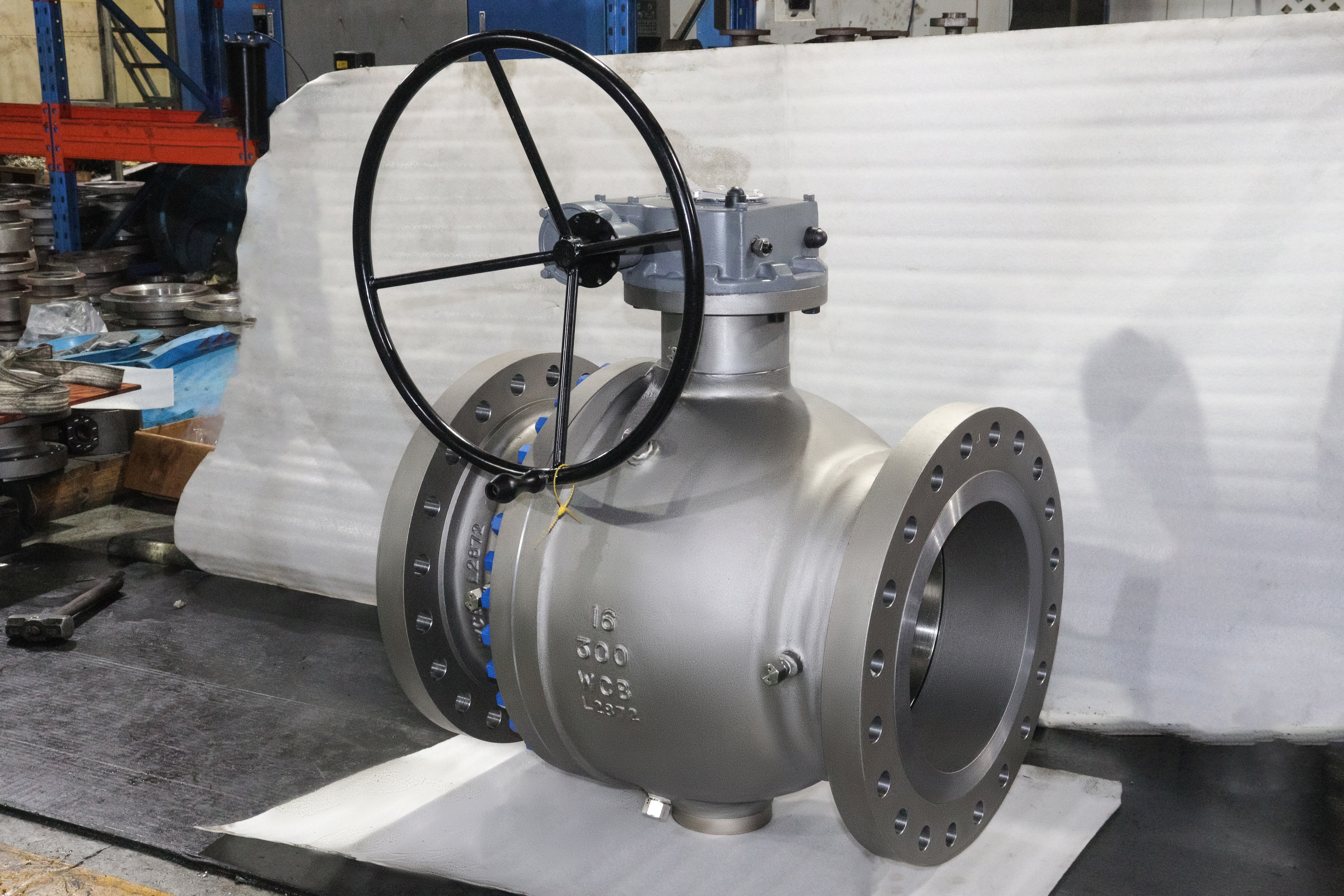
This is a sixteen inch, DN400, two piece side entry trunnion mounted ball valve with a body cast in ASTM A216 WCB, rated ASME Class 300, flanged to ASME B16.5, full bore, and operated by a gear unit. The ball is carried on an upper and a lower trunnion rather than floating on the seats, which is the structural difference that matters at this size: the thrust from the line pressure goes into bearings instead of into the seat rings, and the operating torque stays low enough for a gear to turn by hand.
The first engineering question on a valve this size is not pressure. It is weight, and the weight is in three places at once. The ball itself is a heavy casting, the body is heavy enough that it has to be lifted by a crane rather than by two people, and the pipe it is bolted into has its own weight and its own thermal movement. All three loads arrive at the same place, which is the body joint and the trunnion bearings, and the design has to carry them without letting the ball move off its seat.
That is the argument this page is built on. The pressure class, the flange drilling and the face to face length can all be looked up, and they are looked up on other pages. What cannot be looked up is what happens to a ball of that mass sitting on two trunnions with a running clearance in the bearings, and what that does to the two seats, which are no longer loaded the same way as they are on a six inch valve.
Design and Construction of the Large Two Piece Trunnion Body
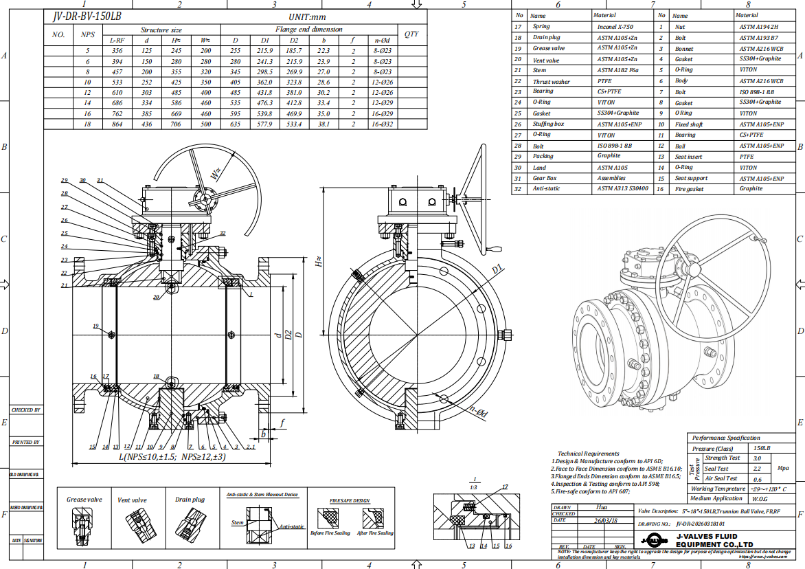
The body is split into a main body and one end closure with a single bolted joint. At this size the joint is not a convenience for maintenance, it is a structural connection that carries the end load: the pressure acting on the closed end closure has to be transferred into the main body through the studs and through the joint faces, and the faces are therefore wide, machined flat and located on a spigot so that the two halves cannot slide relative to each other under load. A body joint that relies on the studs alone to hold alignment will move, and a moved joint leaks.
The trunnions are not integral with the ball at this size. The ball carries a bore at top and bottom, the trunnions are separate parts fitted into those bores, and each trunnion runs in a bearing block that is a separate component located in a machined pocket in the body. That is the arrangement that separates this valve from a small trunnion valve, where the trunnion runs directly in a bore in the body. The blocks are replaceable, they can be made in a bearing material rather than in the body material, and their alignment is set by machining the two pockets in one setting rather than by trusting the casting.
The body also carries feet. On a valve of this mass the pipe is not a support, and a valve hung on two flanges with nothing underneath puts its own weight into the joint and into the pipe, which is how flanges end up out of parallel and gaskets end up leaking. The feet are shimmed to a structural support so that the valve sits on the steel rather than hanging from the pipe, and the shimming is done after the flanges are bolted, not before, because the pipe position is what the valve has to meet.
| Component | Standard Material | Optional Upgrade | Service Notes |
|---|---|---|---|
| Main body and end closure | ASTM A216 WCB cast carbon steel | A217 WC6, A352 LCC | Heavy sections are ultrasonically examined |
| Ball | A105N or WCB with hard chrome | 304 or 316 stainless | Lapped after the trunnion bores are machined |
| Trunnion | Forged or rolled carbon steel | 17-4PH | Fitted into the ball bore, not integral |
| Bearing block | 440C stainless with a self lubricating liner | Nickel alloy bearing | Separate part in a machined pocket |
| Stem | 17-4PH precipitation hardening stainless | 316 stainless | Keyed to the ball, sealed above the bearing |
| Seat | PTFE, RPTFE or PPL, spring loaded | Nylon for low pressure, metal seat with hardfacing | Spring set keeps the seat on the ball at low pressure |
| Seat Sealant | Injection port on the seat ring | Double block and bleed arrangement | Port position depends on the seat type ordered |
| Packing | Flexible graphite | PTFE with an anti extrusion ring | Gland at the top of the neck, adjustable |
| Body joint | Metal to metal faces on a spigot with an O ring | Graphite gasket | Joint carries the end load at this size |
| End connection | Raised face or ring joint, ASME B16.5 Class 300 | Weld ends as a different body | Facing named on the order |
| Operator | Gear unit with a handwheel | Bevel gear, pneumatic, electric | Gear is mandatory at this size, not optional |
Material Options and Where WCB Reaches Its Limit at DN400
WCB is the standard cast carbon steel for valve bodies and is right for water, oil, gas and steam inside the group 1.1 temperature range. What changes at DN400 is not the grade but the casting. A body of this size has heavy sections at the flanges and at the joint faces and thin sections in the bore wall, and the difference in cooling rate between them is what produces shrinkage porosity if the risers are not designed for it. The grade is the same as it is on a two inch valve; the casting is a different problem.
That is why the examination matters more here than the certificate. A heavy section WCB casting is normally ultrasonically examined at the joint faces and around the seat pockets, and the acceptance is agreed with the buyer rather than left to the foundry's own standard. Radiography is possible but on a body this size it covers a fraction of the volume, so it is used to resolve a specific indication rather than as a general screen. A buyer who asks for full radiography on a DN400 body is asking for something that sounds rigorous and covers less than the ultrasonic examination it displaces.
The trim choices follow the duty rather than the size. A hard chrome ball against a soft seat is standard and is right for clean fluids, and a stainless ball or a metal seat is specified where the medium is abrasive or the temperature is above what the seat compound will take. The stem is 17-4PH in the standard build because the torque at this size is carried through a keyed connection, and the key is the part that fails if the gear is over-torqued. The bearing blocks are the parts that see the ball weight, and their material is chosen for a low friction coefficient under a high static load rather than for hardness.
Technical Specifications
The rows that carry weight on this page are the ones about support and about the seat springs, because those are the two items that a buyer of a small valve never has to think about and a buyer of this one does. The pressure class, the drilling and the length are looked up and settled. What is not settled by a table is how the valve is held up and how the seats stay in contact when there is nothing in the line to push them.
The class is recorded as ASME Class 300, which API 6D clause 7.2 records as PN 50 in the metric designation, and the page keeps that as a note rather than as a name. The designation is not what decides anything about a valve this size. What decides is that the flanges are drilled to B16.5 for NPS 16 Class 300, that the face to face length follows B16.10 for that size and class, and that the body joint is strong enough to carry the end load that the bore area produces at the design pressure.
The bore row deserves a note of its own because at this size it is a purchasing decision rather than a preference. A full bore valve passes a pig, which is the reason most sixteen inch mainline valves exist, and the bore is therefore not a trim option but the function. A reduced bore valve at this size is a different product for a different duty, and the two should never be quoted as alternatives on the same line item, because the pipeline design that needs one of them does not work with the other.
| Item | Value |
|---|---|
| Product type | Two piece side entry trunnion mounted ball valve, full bore, gear operated |
| Nominal size | NPS 16, DN400 |
| Pressure class | ASME Class 300, recorded as PN 50 in API 6D clause 7.2 |
| Rating basis | ASME B16.34, material group 1.1 |
| Body material | ASTM A216 WCB cast carbon steel |
| Body joint | Metal to metal faces on a spigot with an O ring, studs carry the end load |
| Ball | A105N or WCB, hard chrome plated |
| Trunnion | Separate trunnion fitted into the ball bore, running in a bearing block |
| Bearing block | 440C stainless with a self lubricating liner, replaceable |
| Stem | 17-4PH, keyed to the ball, sealed above the bearing |
| Seat | Spring loaded soft seat, PTFE, RPTFE or PPL |
| Seat spring note | The spring set is what holds both seats on the ball at low line pressure |
| Seat sealant | Injection port on the seat ring, arrangement declared on the order |
| Packing | Flexible graphite, gland adjustable at the neck |
| End connection | Raised face or ring joint, ASME B16.5 Class 300, NPS 16 |
| Face to face | ASME B16.10 for NPS 16 at Class 300 |
| Bore | Full bore, sized to pass a pig |
| Operator | Gear unit with a handwheel, bevel or worm |
| Body support | Feet cast on the body, shimmed to a structural support |
| Lifting | Slings around the body, never around the gear or the neck |
| Anti static | Ball to body through the stem and the trunnion |
| Fire safe | Metal shoulder behind the seat, tested to API 607 |
| Product standard | API 6D, with API 608 inside its flanged scope at this size |
| Test standard | API 598, with the 6D records where the order asks for them |
| Certification | EN 10204 3.1 with heat number and part number |
| Casting examination | Ultrasonic at the joint faces and seat pockets, radiography on request |
| Temperature, body | Per ASME B16.34 group 1.1 at Class 300 |
| Temperature, valve | Set by the seat compound ordered, below the body ceiling |
Standards and Compliance
ASME B16.34 rates the body from the group 1.1 table, where the allowable pressure is listed against temperature for the material group rather than for the grade. WCB sits in group 1.1 with the other carbon steels, and the rating of this valve at its design temperature is a lookup in that table rather than a conversion from the class number. At DN400 the point of the lookup is not the class but the design temperature, because a body this thick is not the limiting item and the seat is, which is why the temperature row in the specification has two lines rather than one.
ASME B16.5 governs the flanges and ASME B16.10 governs the length, and both are looked up by size as well as by class. The facing is named on the order because a raised face and a ring joint take different gaskets and different stud lengths, and at this size a mistake in stud length is a mistake measured in days rather than hours. Where the line is insulated or the flanges are enclosed, the facing also decides whether the joint can be broken without cutting insulation back, which is a maintenance consideration rather than a design one.
API 6D is the product standard for a pipeline valve and is the document this valve is built to. API 608 also covers it, because 608 takes flanged valves from DN15 to DN600 at Class 150, 300 and 600, and sixteen inch sits at the top of that range rather than outside it. The distinction matters at the next size up: a twenty inch Class 300 valve is outside the 608 flanged scope on diameter alone and has to be a 6D valve, which is one of the reasons large bore specifications usually call 6D throughout rather than mixing the two.
| Requirement | Standard | What J-VALVES Supplies |
|---|---|---|
| Body rating | ASME B16.34 group 1.1 | Class 300 rating read at the design temperature |
| Flange drilling | ASME B16.5, NPS 16 Class 300 | Drilling and facing as ordered, raised face or ring joint |
| Face to face | ASME B16.10, NPS 16 Class 300 | Dimension held on the signed general arrangement drawing |
| Product design | API 6D | Body joint, trunnion support, seat and sealant arrangement |
| Product design, secondary | API 608 within its flanged scope | Applies at this size, stops at DN600 |
| Pressure test | API 598, or the API 6D records | Shell and seat test with a record per valve |
| Fire test | API 607 | Certificate on the seat compound supplied |
| Casting examination | Ultrasonic, acceptance agreed with the buyer | Report at the joint faces and the seat pockets |
| Material certificate | EN 10204 3.1 | Heat number traced to the casting and the test record |
Manufacturing Process
The casting is the long lead item and the operation that decides whether the rest of the schedule holds. A DN400 WCB body is poured in a mould that has to be dried thoroughly, because a body this thick traps moisture and a steam pocket in a heavy section produces porosity that no amount of machining will remove. The risers are sized to feed the flange and joint sections while the bore wall is still liquid, and the pattern has to allow for the shrinkage between those two cooling rates, which is a different allowance from the one used on a small valve.
Machining is done on a horizontal boring machine rather than on a lathe, and the sequence is the whole quality story. The body joint face is machined first, then the two trunnion pockets are bored from the joint face as the datum so that the upper and lower bearings are coaxial with each other and square to the joint. If the pockets are bored from the casting instead, the two bearings end up slightly out of line, the ball sits tilted, and the seats have to absorb an error that no seat spring can correct.
Assembly starts with the ball and the trunnions, because the ball has to be lapped after the trunnion bores are machined and before the seats go in. The ball is then lowered into the main body, the end closure is fitted and the joint is made up to the specified bolt load rather than to a feel, since at this size the difference between a joint that is tight and a joint that is correctly loaded is measured in whether it leaks after a thermal cycle. The gear unit is fitted last, and its travel stops are set against the ball position rather than against the gear housing.

Quality Control and Testing
Casting examination comes first and is the step that most affects the outcome, because everything after it assumes a sound body. Ultrasonic examination is applied at the joint faces and around the seat pockets, which are the two places where a heavy section meets a machined face and where porosity becomes a leak path. The acceptance criteria are agreed in writing before the first body is poured, because a foundry's own standard and a pipeline operator's standard are not the same document, and a disagreement discovered at the witness point is a schedule problem rather than a quality problem.
Dimensional inspection covers the flange drilling, the face to face length, the joint face flatness and the alignment of the two trunnion pockets. The pocket alignment is checked with a mandrel through both bearings rather than with a caliper on each, because the error that matters is the relative one. The ball is then checked for sphericity and for the contact pattern against both seats, and the seats are checked for spring travel, since a seat spring that is coil bound will hold the seat off the ball at low pressure and produce a valve that leaks only when the line is empty.
Pressure testing follows API 598 with a shell test on the assembled body and a seat test in both directions. On a valve this size the shell test is also the proof of the body joint, and the joint is examined around its full circumference rather than at a few points. The gear is then operated through several full cycles against the test pressure to confirm that the torque stays inside what a handwheel can deliver, and the seat injection ports, where fitted, are proved to take a sealant fitting and to pass sealant to the seat.
| Step | What Is Checked | Standard or Acceptance |
|---|---|---|
| Casting examination | Porosity at the joint faces and seat pockets | Ultrasonic to the criteria agreed with the buyer |
| Joint face machining | Flatness and squareness to the bore | Flat within the drawing tolerance, checked on a surface plate |
| Trunnion pockets | Coaxiality of the upper and lower bearing | Mandrel through both bearings before assembly |
| Ball geometry | Sphericity and contact pattern on both seats | Lapping checked with marking compound |
| Seat springs | Free length and travel under load | Not coil bound at the installed height |
| Shell test | Body, joint and packing under pressure | API 598, no leakage or sweating at the joint |
| Seat test | Both directions, seat compound as shipped | API 598 seat test at the rated pressure |
| Gear operation | Full cycles against test pressure | Torque inside the handwheel limit, stops set on the ball |

Applications and Industry Service
The main duty for a sixteen inch full bore trunnion valve is mainline isolation on a transmission line, and the reason it is full bore is pigging. A pipeline that is inspected by an intelligent pig needs a bore that the pig can pass without being deflected, and a valve that is a fraction undersized at the bore is a place where a pig either stops or arrives damaged. That is why the bore row is a functional requirement on this size rather than a trim choice, and it is why a reduced bore valve is a different product rather than a cheaper version of this one.
The second duty is at a terminal or a tank farm, where the valve isolates a line that is emptied and refilled rather than flowing continuously. That duty is harder on the seats than continuous flow, because every drain cycle moves the ball across the seat with the line pressure dropping, and the seat sees the transition from pressure loaded to spring loaded every time. A spring loaded seat is the arrangement that survives this, and the spring set is the part that should be checked on a valve that has been in that service for years.
The third duty is water transmission, where the body material and the coating matter more than the trim. WCB in a buried line needs an external coating that survives handling, because a coating damaged during installation becomes a corrosion cell rather than a protected surface, and a valve this size is difficult to recoat in place. Where the line is aggressive internally, the answer is a lining or a different alloy rather than a thicker wall, since the wall is not what fails first.

Installation, Operation and Maintenance
Lifting is the first thing that goes wrong on a valve this size. The slings go around the body, never around the gear unit, the handwheel or the neck, because those are not designed for the load and a bent gear shaft turns a straightforward installation into a repair. The valve should be lifted in the position it will be installed in where the space allows, since rotating a heavy valve on a sling is how the gear gets damaged even when the slings are right.
The flanges are bolted before the feet are shimmed, and the order matters. The valve is brought to the pipe, the joint is made up, and only then are the feet packed to the structural steel so that the valve neither hangs from the pipe nor pushes up on it. A valve that is shimmed first and bolted second will load the joint with whatever misalignment the pipe has, and at this size that load is large enough to open a joint that was correctly tightened. On a buried line the support is the bedding rather than steel, and the same principle applies with the valve sitting on compacted material rather than on a void.
Operation is by gear and the gear is not optional. The handwheel effort is set by the gear ratio, and a valve that needs more effort than one person can apply comfortably will be operated with a bar on the handwheel, which is how gearboxes and stems are broken. Maintenance is the packing gland, the seat injection ports where fitted, and at long intervals the seats and the ball, which are reached by splitting the body joint. That is a crane job rather than a maintenance job, and it is the reason the body joint is designed to be made once and left alone.
How to Specify and Order
An order for this valve begins with the four items that define the shape: NPS 16 and DN400, ASME Class 300, the facing, and the bore. The facing has to be named as raised face or ring joint with the ring number where a ring joint is ordered, and the ring listed as a separate line, because at this size a missing ring stops an installation. The bore has to be named as full or reduced and not left to the supplier, since the two are different products and a pig will find the difference.
The second block is the materials and the internals: body grade, ball grade and finish, trunnion and bearing material, stem alloy, seat compound and spring arrangement, packing, and whether a sealant injection port or a double block and bleed arrangement is required. Each of those should be written out rather than offered as a list with alternatives, because on a valve this size a change of seat compound changes the spring set as well, and the two have to be ordered together rather than discovered at assembly.
The third block is the operator and the site interface: gear type and ratio, handwheel orientation, whether an actuator is fitted and if so its fail position, the support arrangement, the lifting points, and the coating for the environment the valve will sit in. The last block is the paperwork: the API 598 record, the 6D records where the order asks for them, the EN 10204 3.1 certificate traced to the heat number, the ultrasonic report on the casting, and the fire certificate on the seat compound supplied. A large valve is bought once and lived with for decades, so the documents are part of the product rather than an attachment to it.
FAQ
Q: Why is a full bore valve used at this size?
A: Because the line is inspected and cleaned by pig, and a pig has to pass the valve without being deflected. A bore that is a fraction undersized is a place where an instrumented pig either stops or arrives damaged, and the cost of recovering a stuck pig is far above the difference in price between a full bore and a reduced bore valve. That is why the bore is a functional requirement here rather than a trim option.
Q: What keeps the seats against the ball when the line is empty?
A: The springs behind the seat rings. On a trunnion valve the seat is not pushed onto the ball by the line pressure alone; a coil spring set sits between the seat ring and the body and provides the initial thrust that makes the seal at low or zero pressure. Once pressure rises, the pressure acts on the seat area and adds to the spring force. Without the springs the valve would only seal when the line was pressurised.
Q: Does the weight of the ball affect sealing?
A: It can, and it is the reason this page leads with gravity. The ball runs on two trunnions with a running clearance in the bearings, so it can sit slightly low, and the lower seat therefore carries a little more of the ball load than the upper one. The spring set is sized to keep both seats in contact despite that, and the check at assembly is the contact pattern on both seats rather than on one.
Q: Is API 608 valid for a sixteen inch valve?
A: Yes, and it is the largest diameter at which it is. API 608 takes flanged valves from DN15 to DN600 at Class 150, 300 and 600, so DN400 is inside the range and a twenty inch valve at the same class is outside it on diameter alone. That is one reason large bore specifications usually call API 6D throughout instead of mixing the two standards across a line.
Q: Why are there feet on the body?
A: Because a valve of this mass cannot be supported by the pipe. Hanging it on two flanges puts its own weight into the body joint and into the pipe, and the result is flanges that are no longer parallel and gaskets that leak after a thermal cycle. The feet are shimmed to structural steel so the valve sits on the steel, and the shimming is done after the flanges are made up so that the valve does not push the pipe out of line.
Q: Why a gear unit rather than a lever?
A: Because the torque at this size is beyond what a lever should be asked to deliver, and because a lever that is long enough would be a hazard on an operating platform. The gear ratio converts the torque into a handwheel effort that one person can apply, and the gear also holds the valve in position without a latch. A bar slipped over a handwheel to get more leverage is how gearboxes and stems are broken.


Hot Products


News
Ball Valve Condition Monitoring: Which Signals Actually Predict A Failure
Torque signatures, acoustic emission, differential pressure and digital twin residuals: which measurements find a failing ball valve early.
Read More
Ball Valves in SWRO Desalination: The High Pressure Section Where Ordinary Seawater Valves Fail
Why SWRO high pressure valves fail early: recovery arithmetic, crevice temperature, ERD ripple, scale, letdown cavitation and surge.
Read More
Air Test And Water Test For Ball Valves: What Each Medium Can Prove
A ball valve can pass a hydrostatic seat test and still leak gas. Why air and water prove different things, and how to read a bubble, decay or helium test.
Read More
Ball Valve Flange Bolting: Preload, Relaxation And The Fasteners That Decide Leakage
A weeping flange is rarely the gasket. Preload, torque scatter, hardness limits and thermal relaxation decide whether the joint holds at 100 bar and 400 C.
Read More