


CHINA J-VALVES Offers Various High-quality I ndustrial Ball Valves
J-VALVES, a distinguished professional ball valve manufacturer rooted in China, takes pride in its extensive product portfolio. Our offerings span a wide range, including trunnion-mounted ball valves, floating ball valves, high-temperature ball valves, high-pressure ball valves, metal-sealed ball valves, ultra-low temperature ball valves, DBB ball valves, Three-way And Four-way Ball Valve, and fully welded ball valves. Each product is a testament to our commitment to precision engineering and reliable performance. Meticulously crafted, they are designed to not only meet but exceed the most stringent industrial demands, ensuring stable operation even under extreme conditions. This enables us to provide our clients with high-value services and makes our valves widely sought-after in industries.
Product Category
Contact Us

-
J-VALVES-Q347F
-
J-VALVES
Overview of the J-VALVES 12x10 Class 2500 Trunnion Ball Valve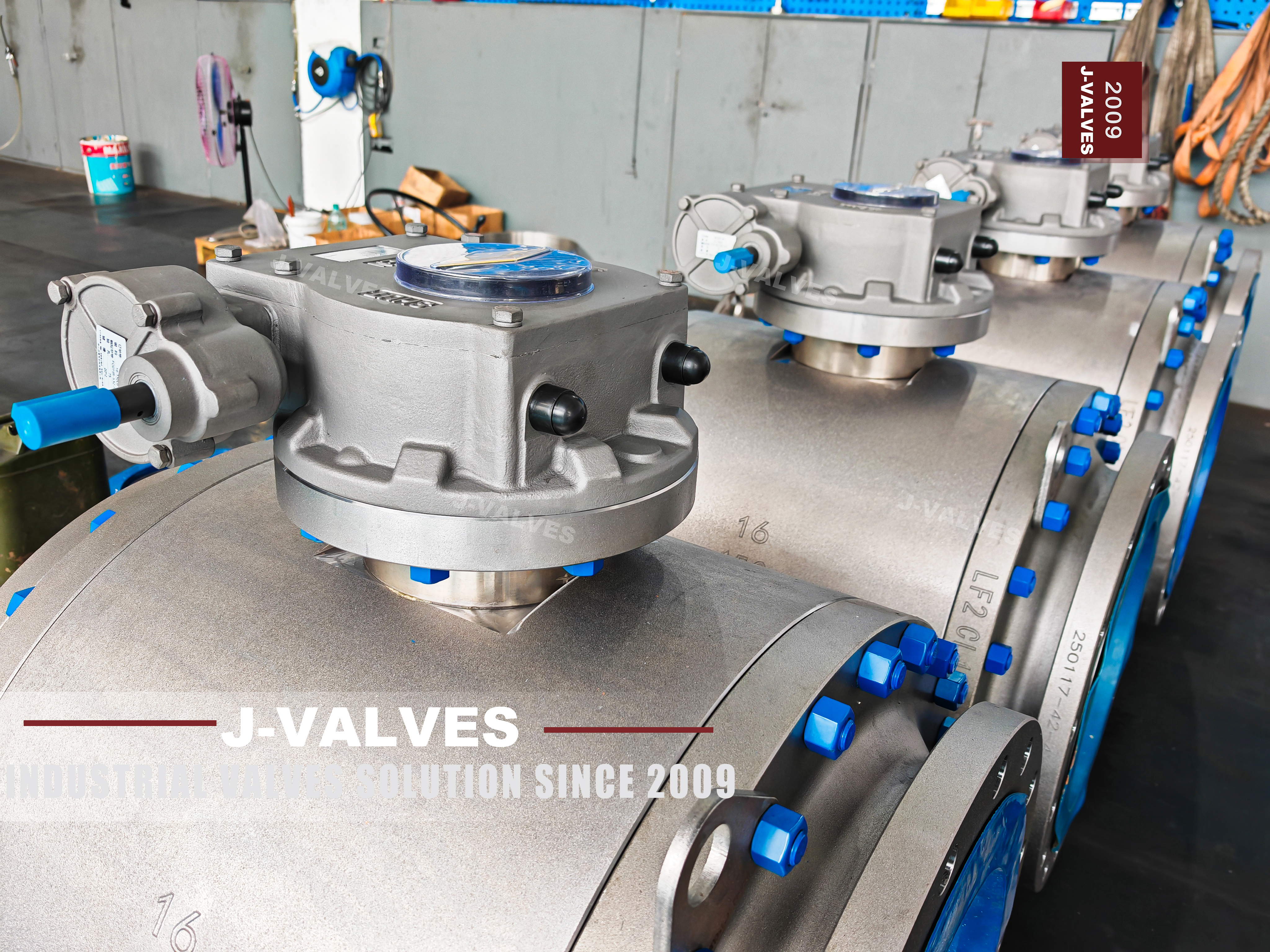
This valve sits on the last row of a table. ASME B16.5 defines Class 2500 flanges from NPS one half to NPS 12, while every other class runs to NPS 24, and ASME B16.47 begins at NPS 26 with no Class 2500 row at all. So NPS 12 is not one size among many at this rating. It is the largest flanged connection that a published dimension exists for. Above it, the joint stops being a standard and becomes a calculation, and a 14 inch Class 2500 enquiry has to be answered with something other than a flange table.
The page is also a good example of a reduced bore written so that it can be read two ways. 12x10 means both end flanges are NPS 12 with a full ring of studs and a ring joint groove, and the passage through the ball is NPS 10. It is not a valve with reducer flanges bolted on. The reduction is internal, at the ball and the seat rings. The consequence is worth stating plainly: the face to face and the bolt circle are those of a 12 inch valve, so it will not fit where a 10 inch valve fits.
Three lines on the original listing were never reconciled with each other. The meta description is the string 12x10, cut off at the inch mark in the product name, because that character closes the attribute early and the rest of the sentence is discarded; the search snippet is therefore two numbers. API 608 is cited next to Class 2500. And a duplex body shares one temperature range with carbon steel, and a second range appears further down the same page. The valve in the photograph is sound; the specification table around it is not, and those lines are replaced here.
Design and Construction
The body is three piece and side entry: a middle body carrying the ball and both seats, closed by two end bodies. Each of those two joints is a full pressure boundary at Class 2500, and each is closed by its own ring of studs rather than by the pipe flange bolting. That is what the blue nuts in the photograph are, and it is why the valve can be opened for seat work without being cut out of the line. The price of that convenience is two extra joints that both have to hold full class pressure.
The ball is carried on upper and lower trunnions running in metal backed self-lubricating bearings, so the thrust from line pressure goes into the bearing blocks and not into the stem. The original listing states the arrangement correctly: below four inch the trunnions sit in the primary body, and from six inch up they sit in two separate bearing blocks. At NPS 12 this is the second kind, and it is the only reason one person can turn it. Torque still rises with pressure, because seat load rises with pressure, so the gear ratio comes from a measured breakaway figure rather than from a catalogue column.
Two more structural facts are visible and worth naming, because neither appears in the listing. The body carries welded support feet at both ends, which tells you the valve is expected to sit on a structure rather than hang between two flanges, and it tells the piping designer to treat the valve as a piece of equipment with a mass of its own. And the stem is retained by the bolted body cover, with the gland plate on top, so it cannot be blown out and the gland can be repacked with the valve in line.

Material Options
The nameplate resolves the material question that the listing leaves open. It reads 12x10, then 2500, then F51, and the rim of the body joint flange is stamped F51 again beside a heat number that the photograph does not resolve cleanly. F51 is duplex stainless, UNS S31803 in ASTM A182, and it is a forging grade rather than a catalogue code, which matters because catalogue codes on this site have been mistaken for grades before. Everything inside the cavity is invisible here, so the ball, stem and seat ring grades come from the EN 10204 3.1 certificate and from nothing else.
Why duplex at this class is a fair question, because a forged carbon steel body would be cheaper. Duplex carries roughly twice the yield strength of an austenitic grade and resists chloride stress corrosion, so a 12 inch Class 2500 body can be built with less wall and less mass than the austenitic route would need. Those savings are not printed on this page, because wall thickness is a drawing value from the design calculation. Duplex also earns its place in wet, chloride bearing service and loses it in hot service.
The temperature line is where the listing does real damage. It gives -29 to +425 °C for a menu that includes A105, A694 forgings, F304, F316 and F51. The 425 °C figure is the carbon steel group 1.1 ceiling, so it is correct for one grade out of five and wrong for the one that is stamped on this body. Duplex embrittles well below it, with 300 °C the customary ceiling for 2205 in pressure service and the ferrite phase turning harmful through the 300 to 500 °C band. The same page also prints a standard temperature of -29 to +220 °C elsewhere, so it states two ranges and neither one fits F51.
| Component | Standard Material | Optional Upgrade | Service Notes |
|---|---|---|---|
| Body and closures | ASTM A182 F51 duplex stainless forging, as stamped | A105 or A694 carbon steel, F304 or F316 austenitic | Grade is fixed by the stamp and the certificate, not by the title |
| Ball | F51 with hard chrome plating | Nitrided or ENP | Plating thickness is a drawing value |
| Seat rings | Metal seat, tungsten carbide or chromium carbide overlay | ENP overlay | Hardfacing is what makes a metal seat hold at this class |
| Stem | F51 duplex | 17-4PH where a smaller stem section is needed | Anti blowout, retained by the body cover |
| Stem sealing | Graphite packing, two O-rings and a gasket | Low emission packing to ISO 15848 | Triple barrier as photographed at the gland |
| Body joint bolting | ASTM A193 B7 | B16 for elevated temperature | Preload from the signed drawing, not from a rule of thumb |
| End flange gasket | ASME B16.20 ring joint, octagonal or oval | Ring material named on the order | A ring harder than the groove damages the groove |
| Trunnion bearings | Metal backed, self-lubricating | — | Takes the pressure load off the stem |
| Body style | Three piece, side entry, two bolted joints | Two piece on request | Both joints are pressure boundaries |
| Operator | Worm gear with handwheel, as photographed | Pneumatic, electric or hydraulic | Gear ratio set by measured torque |
Technical Specifications
Every value below can be checked one of three ways: from the nameplate, from a table in a published standard, or by looking at the valve. The plate gives the bore, the class and the grade. The photograph gives the ring joint groove, the studded body joints, the gear operator and the support feet. The standards give the flange envelope, the groove profile and the test pressures. Nothing here is obtained by arithmetic, and nothing is carried over from a table for another class. Torque and mass are absent on purpose, and both come with the drawing.
Class 2500 and PN 420 appear together on one line because API 6D clause 7.2 puts them there, and the spacing matters only in paperwork: the standard writes the designation with a space, the trade and the URL write it as PN420, and both name the same row of the same table. That is also why the flange can only be ASME B16.5. EN 1092-1 runs from PN 2.5 to PN 400, so no European flange exists at this level, and an RTJ joint here is defined in B16.5 and B16.20 alone. The procuring consequence is immediate: the mating flange is a B16.5 Class 2500 flange at NPS 12.
What the table deliberately omits is as informative as what it carries. Face to face, bolt circle, bolt hole size, ring groove number and mass are all absent, because each one belongs to a table read against a specific size and class and then fixed on a signed drawing. The size data sheet attached to the original listing is a generic trunnion table and does not describe this valve. The listing's own explanation of 12x10 is also off the point: it talks about saving wall thickness, when the class is untouched and the change is at the ball.
| Item | Value |
|---|---|
| Nominal bore | NPS 12 x NPS 10 (DN 300 x DN 250), reduced bore |
| Bore reading | Both end flanges are NPS 12; the passage through the ball is NPS 10. Not reducer flanges |
| Pressure class | Class 2500 |
| Pressure designation | PN 420, the Class 2500 row of the seven designations in API 6D clause 7.2 |
| European flange note | EN 1092-1 stops at PN 400, so no EN flange exists at PN 420; ASME B16.5 is the only option here |
| Flange size limit | B16.5 covers Class 2500 only to NPS 12, which is this valve; B16.47 starts at NPS 26 with no 2500 row |
| Body material | F51 duplex stainless forging, as stamped on the nameplate |
| Body construction | Three piece, side entry, two bolted body joints |
| End connection | Flanged, ring joint face, ASME B16.5 |
| Ring joint groove | ASME B16.20, octagonal or oval per order, profile recorded at inspection |
| Face to face | ASME B16.10, value taken from the signed drawing |
| Seat | Metal to metal, hardfaced seat ring lapped to the ball |
| Seat effect | Single or double piston effect per order; the choice decides cavity relief |
| Body cavity relief | A double piston seat does not self relieve; liquid service needs single piston seats or a relief device |
| Temperature, body | Taken per material: carbon steel to the group 1.1 ceiling, duplex to the material data sheet, austenitic to its own table |
| Pressure test | API 598, shell at one and a half times and seat at one and one point one times |
| Design standards | ASME B16.34 and API 6D |
| Not applicable | API 608 stops at Class 600 for flanged valves and excludes double piston trunnion seats |
| Support | Welded body feet as photographed; weight is carried off the pipe |
| Operator | Gear operated, handwheel; pneumatic, electric or hydraulic on request |
| Torque | Breakaway, running and seating measured on the assembled valve, issued with the drawing |
| Traceability | Heat number on the body matched to the EN 10204 3.1 certificate |
Standards and Compliance
Four of the five standards cited on the listing apply, and each does a specific job. ASME B16.34 is the pressure temperature basis for the shell, and for a duplex body the allowable values are read from the material's own table rather than borrowed from the carbon steel group 1.1 column. API 6D is the product standard and the only document that authorises the PN 420 label. ASME B16.10 sets face to face by class and size and carries a Class 2500 row. ASME B16.20 covers the ring joint that the groove is cut for.
API 608 does not apply, and there are two independent reasons. Flanged valves under API 608 stop at Class 600, so Class 2500 is outside its pressure scope before size is even considered. And clause 1.7 puts trunnion valves fitted with double piston effect seats outside the standard altogether. The original listing cites API 608 on the same page as a seat table offering double piston seats, which means it cites a document that excludes its own preferred option. Either the citation goes or the seat table does; they cannot both stay, and the seat table is the one describing the valve.
Two more citations on the listing are simply the wrong documents. ASME B16.47 is the large diameter flange standard and has no row at NPS 12 or at Class 2500, so it cannot be offered as an alternative to B16.5 here; naming it at this size tells a piping engineer that the page was assembled from a template. API 6DSS is the subsea pipeline specification and API 6A PSL 4 is a wellhead specification; neither describes a ring joint flanged valve for a land line. Listing them under the heading of licences invites a check in the API monogram directory that the listing will not survive.
| Requirement | Standard | What J-VALVES Supplies |
|---|---|---|
| Pressure temperature basis | ASME B16.34, values per material | Rating table for the grade stamped on the plate |
| Product standard | API 6D | Certificate of compliance, with the PN 420 to Class 2500 row identified |
| Face to face | ASME B16.10 | Dimension from the signed GA drawing |
| Flange dimensions | ASME B16.5, Class 2500, NPS 12 | Flange record against the B16.5 table for this size and class |
| Ring joint gasket and groove | ASME B16.20 | Groove profile record, ring material named on the order |
| Shell and seat test | API 598 | Test record with the pressures actually applied |
| Material identification | EN 10204 3.1 | Heat number matched between plate, certificate and drawing |
| Duplex phase balance | Works procedure on the finished forging | Ferrite content and hardness recorded |
| Fire safe, when ordered | API 607 or ISO 10497 | Certificate attached to the unit and the heat |
| Low emission, when ordered | ISO 15848 | Test report naming the packing and the leakage class |
Manufacturing Process
F51 is a forging grade, so the body does not begin as a casting. Billets are forged to a shape close to the finished body so that the grain flow follows the pressure boundary, then solution annealed and water quenched to put the alloy back into a balanced two phase structure before any machining starts. That order is not optional on duplex, and the quench is part of it: a slow cool leaves the wrong phase balance in a body that will never be corrected afterwards. Machine first and anneal later, and every finished dimension moves.
The seat pockets and the stem bore are then weld overlaid. The listing names tungsten carbide, chromium carbide and ENP as the seat options, and at Class 2500 the overlay is not decoration: a metal seat has to be hard enough to survive repeated seating at full differential without galling, and it has to be repairable in a body that cost far more than the overlay. After overlay the seat ring is machined and lapped against its own ball, and the two stay together as a matched pair through assembly, test and despatch.
Duplex imposes one discipline that austenitic grades do not. The material must not be held in the 300 to 500 °C band, where the ferrite phase starts to form sigma and toughness falls away, so interpass temperature is controlled during welding and overlay, and any weld repair is followed by a fresh solution anneal rather than a local touch up. That single rule is the practical difference between a duplex shop and a stainless shop, and it applies to the heat treatment subcontractor as much as to the welder. It is also why the ferrite check comes after the last thermal operation.

Quality Control and Testing
Three checks belong to duplex specifically and are not covered by a pressure test. Chemistry on the finished forging, a ferrite content check to confirm the phase balance survived the thermal cycle, and hardness, because a duplex body held too long in the wrong band will pass a hydrostatic test and still be brittle. Positive material identification confirms the grade on the body rather than on the paperwork, and a penetrant or ultrasonic examination confirms the overlay before the seat ring is lapped. Each of those records has to carry the heat number.
Pressure testing follows API 598: shell at one and a half times the rated pressure, seat at one point one times, both at ambient. At Class 2500 the shell figure is high enough that the test stand itself becomes a qualification, and the record should show the pressure that was actually applied rather than the class. The seat test is run in both directions, because a bidirectional seat that seals one way and not the other is a seat that was lapped off centre, and that fault will not show up in a single direction test.
The dimensional work is where this valve is won or lost, and none of it shows on a test gauge. The ring joint groove is checked against the groove profile in ASME B16.20, since a groove slightly out of form seals at the factory and weeps after the first thermal cycle on site. Face to face is checked against B16.10 for this size and class, the two end flanges are checked for parallelism and concentricity so that the joint pulls up square, and both body joints are checked for stud preload against the drawing's torque table rather than against a feel for tightness.
| Step | What Is Checked | Standard or Acceptance |
|---|---|---|
| 1. Incoming billet | Heat number against the mill certificate | EN 10204 3.1 |
| 2. Forging and solution anneal | Procedure and thermal cycle record | Works record, retained with the heat |
| 3. Ultrasonic examination | Internal soundness of the forging | Works procedure before finish machining |
| 4. Ferrite content and hardness | Phase balance after the thermal cycle | Works procedure on the finished forging |
| 5. Weld overlay of seat pockets | Thickness, bond, no sigma | Works procedure, penetrant tested |
| 6. Seat and ball lapping | Contact pattern across the sealing face | Drawing, matched pair kept together |
| 7. Ring joint groove | Profile and surface finish | ASME B16.20 groove |
| 8. Face to face and flange faces | Overall length, parallelism, concentricity | ASME B16.10, recorded on the drawing |
| 9. Shell and seat test | One and a half, and one and one point one times rated | API 598, no leakage and rate within spec |
| 10. Body joint preload | Stud load sequence and value | Drawing torque table |
| 11. Marking and documents | Plate against certificate and drawing | API 6D marking, 3.1 certificate |

Applications and Industry Service
Class 2500 flanged valves belong to the part of a plant where pressure is the design driver rather than a margin: high pressure gas metering and letdown, water injection, amine and wash water service in hydroprocessing, high pressure test stands, and manifolds downstream of wellhead equipment where the connection is still flanged. Most of those share two conditions. The line cannot be taken out of service at will, and a leaking joint is not an inconvenience but an incident, which is why the seat and the gasket get more attention than the body.
The reduced bore is a trade made in two directions. In flow terms a 12x10 behaves like a 10 inch valve, so it is chosen where the line is sized for pressure drop rather than for pigging; nothing with a pig will pass the step inside the ball. What it buys is a smaller ball, a smaller seat, a shorter heat path and a much lower operating torque, and at Class 2500 that difference is what keeps the operator a handwheel and a gearbox instead of a hydraulic power unit.
Duplex is the right body material for a narrow band of that work and the wrong one outside it. It earns its place where chlorides and wet gas are present and where the temperature stays well below the embrittling band; it loses to carbon steel on cost, and it loses to austenitic grades at high temperature. The temperature ceiling is the limit most often missed, because corrosion resistance is what sells duplex and nobody asks it to run hot until the line is already specified. That is also why the range on this page is written per material instead of as a single number.

Installation, Operation and Maintenance
This valve is a structural element of the line, not a fitting hanging between two flanges. The welded feet in the photograph exist because the mass at this size and class has to be carried by a structure, and the piping stress analysis needs the mass and the centre of gravity from the drawing before the supports are detailed. Setting a valve of this size on pipe alone loads the flange joint in bending, and a Class 2500 ring joint has very little tolerance for that, whatever the bolt preload. Put the support under the valve body, not under the pipe next to it.
The ring joint is the part most often assembled badly. The ring is used once and replaced, the groove and the ring must be the same profile and the same number, and the studs are brought up in a cross pattern in stages to the value on the drawing rather than until the joint stops weeping. A ring harder than the groove damages the groove on the first make up, and that damage cannot be corrected on site. On a joint this size the difference appears at pressure, not at assembly.
The seat decision has to be made before the order, not after. A double piston seat seals the body cavity from both directions, which is what a double block and bleed arrangement wants, but it also means the cavity cannot relieve itself, so trapped liquid that warms up has nowhere to go and will lift a seat or distort a cavity. Specify single piston seats where the cavity must relieve to the low pressure side, or fit a relief device. The three piece body is the maintenance compensation: the middle body comes out in line.
How to Specify and Order
Eight lines close this valve, and four of them are missing from the original listing. One: bore, written as NPS 12 x NPS 10, so that nobody quotes a reducing flange set. Two: class and designation, Class 2500 and PN 420 together with the API 6D reference. Three: flange facing and ring number. Four: body grade as it will be stamped, F51 confirmed by certificate. Five: seat effect. Six: operator type. Seven: support arrangement and the mass from the drawing. Eight: test standard and certificates. Sour service, if it applies, is a ninth.
With the enquiry, send the fluid, the design and operating temperature, the chloride level if the line is wet, any sour service requirement, the maximum differential across the seat, and the supply available for an actuator. Those answers fix the grade, the seat and the operator, in that order. The two that are most often left out are the differential and the chloride level, and they are the two that decide whether the valve is duplex or carbon steel and whether the seat is single or double piston.
What ships is the valve, the 3.1 certificate matched to the plate, the ferrite and hardness record, the shell and seat test records, the ring groove profile record, and the drawing carrying the dimensions this page deliberately does not print. The plate reads 12x10, 2500 and F51; the certificate explains them; the drawing dimensions them. Those three documents must agree with each other and with the serial number, and they are what a buyer should ask for before the valve is crated rather than after. Any disagreement between them is a reason to stop the shipment and open the valve.
FAQ
Q: Is PN 420 the same as Class 2500?
A: Yes, and the only document that says so is API 6D clause 7.2, which lists seven pressure designations against seven ASME classes: PN 20, 50, 64, 100, 150, 250 and 420 against Class 150, 300, 400, 600, 900, 1500 and 2500. PN 420 is therefore a designation, not a conversion, and the number 420 is not a pressure in bar at any temperature. The practical consequence is on the flange. EN 1092-1 runs from PN 2.5 to PN 400 and stops there, so there is no European flange at this level and the valve can only be built with an ASME B16.5 Class 2500 flange, ring joint face.
Q: What does 12x10 mean, and can both ends be different sizes?
A: It means both end flanges are NPS 12 and the passage through the ball is NPS 10. This is a reduced bore, not a valve with reducer flanges bolted to it: each end carries a full ring of studs and a ring joint groove at NPS 12, and the reduction happens inside, at the ball and the seat rings. Two things follow. The face to face and the bolt circle are those of a 12 inch valve, so it will not fit where a 10 inch valve would. And the bore has a step inside, so a pig cannot pass and liquid can sit in it.
Q: Can I order a 14 inch Class 2500 valve?
A: Not as a standard flanged product, and this valve is the reason the question comes up. ASME B16.5 defines Class 2500 flanges only up to NPS 12; every other class, 150 through 1500, runs to NPS 24. ASME B16.47 covers NPS 26 to NPS 60 and carries no Class 2500 row in either series. So beyond NPS 12 at this rating there is no published flange dimension to work from, and the joint has to be designed and calculated rather than looked up. NPS 12 is the last size where a 2500 lb flanged valve is a catalogue item.
Q: Why does the page not give a single temperature range?
A: Because one range cannot cover the material list, and writing one was the original page's worst line. The -29 to +425 degrees C bracket it printed is the carbon steel group 1.1 ceiling in ASME B16.34, correct for A105 and wrong for the grade stamped on this body. The customary pressure service ceiling for 2205 duplex is around 300 degrees C, above which the ferrite phase starts to turn harmful through the 300 to 500 degrees C band, and an austenitic grade runs to a different table again. Each grade has its own limit, and the limit that applies is the one on the certificate.
Q: Why is API 608 wrong on a Class 2500 valve?
A: Two independent reasons. First, scope: API 608 covers flanged ball valves in Classes 150, 300 and 600 only, from DN 15 to DN 600, so Class 2500 is outside it before size is considered. Second, clause 1.7 places trunnion ball valves fitted with double piston effect seats outside the standard altogether. The original listing cites API 608 on the same page as a seat table that offers double piston seats, so it cites a document that excludes its own option. What actually applies here is API 6D for the product and ASME B16.34 for the shell rating.
Q: Should the seats be single or double piston effect?
A: It depends on whether the body cavity has to relieve, and that is a process decision rather than a valve preference. A single piston seat lets the cavity discharge to the lower pressure side, which is what liquid service needs. A double piston seat gives a double barrier and seals from both directions, which is what a double block and bleed arrangement wants, but the cavity can no longer relieve itself, so trapped liquid that warms up will lift a seat or distort the cavity unless a relief device is fitted. State which one on the order; it cannot be decided after the valve is built.


Hot Products


News
Ball Valve Condition Monitoring: Which Signals Actually Predict A Failure
Torque signatures, acoustic emission, differential pressure and digital twin residuals: which measurements find a failing ball valve early.
Read More
Ball Valves in SWRO Desalination: The High Pressure Section Where Ordinary Seawater Valves Fail
Why SWRO high pressure valves fail early: recovery arithmetic, crevice temperature, ERD ripple, scale, letdown cavitation and surge.
Read More
Air Test And Water Test For Ball Valves: What Each Medium Can Prove
A ball valve can pass a hydrostatic seat test and still leak gas. Why air and water prove different things, and how to read a bubble, decay or helium test.
Read More
Ball Valve Flange Bolting: Preload, Relaxation And The Fasteners That Decide Leakage
A weeping flange is rarely the gasket. Preload, torque scatter, hardness limits and thermal relaxation decide whether the joint holds at 100 bar and 400 C.
Read More