


CHINA J-VALVES Offers Various High-quality I ndustrial Ball Valves
J-VALVES, a distinguished professional ball valve manufacturer rooted in China, takes pride in its extensive product portfolio. Our offerings span a wide range, including trunnion-mounted ball valves, floating ball valves, high-temperature ball valves, high-pressure ball valves, metal-sealed ball valves, ultra-low temperature ball valves, DBB ball valves, Three-way And Four-way Ball Valve, and fully welded ball valves. Each product is a testament to our commitment to precision engineering and reliable performance. Meticulously crafted, they are designed to not only meet but exceed the most stringent industrial demands, ensuring stable operation even under extreme conditions. This enables us to provide our clients with high-value services and makes our valves widely sought-after in industries.
Product Category
Contact Us

-
J-VALVES-Q347F
-
J-VALVES
Overview of the J-VALVES 20x16 Cryogenic Trunnion Mounted Ball Valve
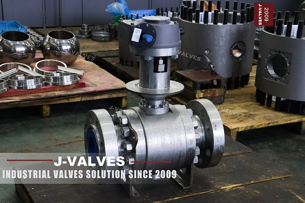
This page is named for a temperature it then declines to claim. The specification table gives the temperature range as -29 °C to +425 °C, which is the range of a carbon steel body in group 1.1 of ASME B16.34, and it is the most damaging line on the page. A valve offered as cryogenic and then described as stopping at -29 °C tells every buyer in an air separation plant that it is not the valve the title promised. The range that belongs on this page is bounded at the bottom by the impact test temperature and at the top by the seat compound, and it belongs on the certificate rather than in a template.
The page contradicts itself twice, and both times against the same fact. Its own service block lists cryogenic as -47 °C to -196 °C, written backwards, and its structural features text talks about an extended bonnet keeping the packing outside the cold box. So the listing says cryogenic, then says ambient, then says cryogenic again. The name and the engineering are right. The specification table was copied from a carbon steel product and never reconciled.
Two things on the page are right, and both are commonly wrong on this site. The first is the bore. 20x16 is a reduced bore, not a pair of reducer flanges: both ends are NPS 20, each with a full ring of studs and a ring joint groove, and the passage through the ball is NPS 16. The second is PN150. In the seven designations of API 6D clause 7.2, PN 150 is Class 900 — not an approximation and not a conversion, but the same row of the same table.
Design and Construction
The ball is carried on upper and lower trunnions that run in metal backed self-lubricating bearings, so line pressure acting on a DN 400 ball is taken by the shafts and the bearing blocks rather than by the stem. The page's own text adds the detail that matters at this size: below four inch the trunnions sit in the primary body, and from six inch upward they sit in two separate bearing blocks. At NPS 20 this valve is the second kind, which is why it can be turned by one person on a handwheel. Torque still rises with pressure, because the seat load rises with pressure, so the gearbox ratio comes from a measured breakaway figure rather than from a catalogue column.
The body is three piece, side entry, closed by two bolted joints. Each of those joints is a pressure boundary carrying full class pressure, and at liquid nitrogen temperature the studs matter as much as the body. A193 B7 bolting is permitted down to -29 °C and not below, because it is a ferritic grade with a transition temperature of its own. The correct bolting here is austenitic, B8 or B8M class, so that the studs contract with the stainless body instead of against it.
The photograph shows the bonnet arrangement without ambiguity: a bolted joint at the body, a long cylindrical extension, then the packing gland with its studs and nuts at the top, under the gearbox. That is the cryogenic arrangement, and it exists to keep the packing at the warm end where graphite and PTFE still behave. The same page also prints a description of an extended stem whose seals sit in the body gland plate. That is the buried valve, not this one.
Material Options
The grade list is where the temperature problem becomes a specification problem. It offers A352 LCB or LCC low temperature cast carbon steel, A350 LF2 forged carbon steel, and A182 F304 or F316. LCB and LCC are impact tested at -46 °C, and so is LF2. None of the three reaches liquid nitrogen. Offering them as alternatives on a cryogenic page is not a range — it is three grades that stop a hundred and fifty degrees short of the service, and one grade, A352 LC9, that would actually reach it. The list also mixes foundry and forge: LCB and LCC are cast, LF2 and the austenitics are forged, so the choice changes the factory and the inspection route as well as the plate.
The nameplate settles which valve this is. It reads 20x16, then 900, then F316, and it carries a bracketed suffix after the grade that the photograph does not resolve cleanly. What the certificate settles is the carbon ceiling, and that is the only difference between F316 and F316L; both are austenitic, both are forged to A182, and both are acceptable at this temperature. The ball and stem in the cavity are not visible at all, so their grades are taken from the 3.1 certificate and from nothing else on this page.
Austenitic is not a preference at -196 °C, it is the reason the valve works. Ferritic steels have a ductile to brittle transition, and below it toughness falls away and a pressure boundary can crack without visibly deforming first. Austenitic stainless has a face centred cubic structure and no such transition, and ASME B31.3 holds its allowable stress at the room temperature value all the way down. The seat is the other half of the answer: PCTFE keeps its shape at liquid nitrogen temperature far better than PTFE does, and PEEK is the option when pressure is high enough that the seat has to be hard.
| Component | Standard Material | Optional Upgrade | Service Notes |
|---|---|---|---|
| Body and closures | ASTM A182 F316 forged austenitic stainless | F316L, or A352 LC9 for a ferritic body | Grade as stamped on the plate; certificate names the heat |
| Ball | F316 with hard chrome plating | Nitrided or ENP | Plating thickness is a drawing value |
| Stem | F316 austenitic | F304, or 17-4PH where a small stem diameter is required | Impact tested as part of the assembled valve |
| Seat rings | PCTFE | PTFE, RPTFE, or PEEK for high pressure | The seat sets the temperature limit of the assembled valve |
| Stem sealing | Graphite, with PTFE V-ring backup | Low emission packing to ISO 15848 | Sits at the top of the extension, in the warm end |
| Body joint bolting | A193 B8 or B8M austenitic | — | B7 is not permitted at this temperature |
| End flange gasket | ASME B16.20 ring joint, octagonal or oval | Ring material named per order | A ring harder than the groove damages the groove |
| Trunnion bearings | Nickel-chromium alloy backed, self-lubricating | — | Takes the pressure load off the stem |
| Operator | Worm or bevel gear, handwheel | Pneumatic, electric, hydraulic, all cold service | Gear ratio set by measured torque |
| Body style | Three piece, side entry, bolted | Two piece on request | Both body joints are pressure boundaries |
Technical Specifications
What follows can be verified three ways: from the nameplate, from a published standard, or by looking at the valve. The plate gives the bore, the class and the grade. The photograph gives the ring joint groove, the studded body joints, the lifting eyes and the two support feet that carry a body of this weight off the pipe. The standards give the flange schedule, the gasket profile and the test pressures. Nothing on this page is derived by arithmetic, and nothing is copied from a table for a different class.
The item table repeats the same discipline. Class 900 and PN 150 appear together because API 6D clause 7.2 puts them in one row. The bore appears as two numbers because the reduced bore is the product, not a mistake in the title. The temperature does not appear as a range at all, because a range that runs from ambient to ambient is not a cryogenic specification; the honest statement is the test temperature written on the certificate, next to the standard it was tested to. Seat effect is the one line a buyer can still change after the fact and should not: a single piston seat relieves the cavity, a double piston seat seals it, and the difference sits in the seat ring rather than in the body.
One warning belongs here rather than in the notes. The size data sheet attached to the original listing is a Class 150 trunnion table with full port and reduced port columns, running from four inch upward. It is six pressure classes away from this valve and every dimension in it belongs to a different body. Face to face, bore and flange thickness for a Class 900 reduced bore valve come from the Class 900 drawing, which is where the numbers on this page are said to live for the same reason.
| Item | Value |
|---|---|
| Nominal bore | DN 500 x DN 400 (NPS 20 x NPS 16), reduced bore |
| Pressure class | Class 900, designated PN 150 in API 6D clause 7.2 |
| Body grade | F316, as stamped on the nameplate |
| Body style | Three piece, side entry, bolted closures |
| End connection | Flanged, ring joint face, ASME B16.5 |
| Ring joint groove | ASME B16.20, octagonal or oval per order |
| Face to face | ASME B16.10, dimension on the signed drawing |
| Design basis | ASME B16.34 group 2.1 for the grade stamped |
| Product standard | API 6D |
| Pressure test | API 598, shell and seat |
| Cryogenic test | BS 6364, at the ordered service temperature |
| Impact test | ASTM A370, three specimens, at service temperature |
| Seat effect | Single or double piston effect, stated per order |
| Operator | Gear operated as standard; pneumatic, electric, hydraulic on request |
| Extension length | Set by the insulation thickness, given at enquiry |
Standards and Compliance
Four of the five standards cited on the listing are right and one is out of scope. ASME B16.34 is the pressure temperature basis and group 2.1 is where F316 sits. API 6D is the product standard and the source of the PN 150 to Class 900 row. ASME B16.10 covers face to face by class and size and has a Class 900 schedule at NPS 20. ASME B16.20 covers the ring joint gasket. Those four carry the valve from the rating table to the groove profile. The material group matters more than the class number: F316 sits in group 2.1, whose ratings are lower than the carbon steel group 1.1 at the same class, and quoting one group's number for the other group's valve is the commonest error in this whole section.
API 608 does not, and the reason is scope rather than pedantry. API 608 is written for flanged ball valves from DN 15 to DN 600 across Class 150 to Class 600, and for threaded ends from DN 8 to DN 50 across Class 150 to Class 800. Class 900 is outside that ceiling, so a certificate of compliance against API 608 cannot be issued for this valve at any size. A listing that names API 608 and Class 900 in the same line is describing two different products, and the buyer only finds out at the witness test.
PN150 carries a second trap. It means Class 900 only because API 6D clause 7.2 says so. EN 1092-1 has no PN 150 at all — it runs from PN 100 straight to PN 160 — so a European reader who takes the designation for a flange rating goes looking for a flange that does not exist. At NPS 20 the flange is ASME B16.5, which runs to NPS 24; ASME B16.47 begins at NPS 26 and has no row here, so the alternative the page offers is not an alternative. Two further documents on the listing do not apply at all: API 6DSS is the subsea pipeline standard, and API 6A PSL 4 is a wellhead specification.
| Requirement | Standard | What J-VALVES Supplies |
|---|---|---|
| Pressure temperature basis | ASME B16.34, group 2.1 | Rating table for the grade stamped on the plate |
| Product standard | API 6D | Certificate of compliance, with the PN 150 to Class 900 row identified |
| Face to face | ASME B16.10 | Dimension taken from the signed GA drawing |
| Ring joint gasket | ASME B16.20 | Groove profile record, ring material named on the order |
| Shell and seat test | API 598 | Test record with the pressures actually applied |
| Cryogenic test | BS 6364 | Cold test record at the ordered temperature |
| Material identification | EN 10204 3.1 | Heat number matched between plate, certificate and drawing |
| Impact testing | ASTM A370 at service temperature | Three specimens per heat, lateral expansion recorded |
| Fire safe, when ordered | API 607 or ISO 10497 | Certificate attached to the unit and the heat |
| Low emission, when ordered | ISO 15848 | Test report naming the packing and the leakage class |
Manufacturing Process
F316 is an A182 forging grade, so the body does not start as a casting. Billets are forged to a shape close enough to the finished body that the grain flow follows the pressure boundary, then solution annealed to put the carbides back into solution before any machining begins. That order matters: machine first and anneal afterwards, and every finished dimension moves. A cast body, by contrast, would be LCB or LCC, with a different factory, a different inspection route and a temperature ceiling of its own.
The forging is ultrasonically examined before finish machining, because a defect at this class and this wall thickness is not something a hydrostatic test will find. The seat pockets and the stem bore are then weld overlaid, and the page offers stainless, duplex and nickel alloy overlay as options. At this temperature the overlay is not primarily about corrosion: it is about the seating pocket surviving repeated disassembly without galling, and about having a repairable surface on a forging that costs more than the overlay ever will. The stem bore takes the same treatment, because that is the surface the packing runs against and the one place where a scratch becomes a leak path at temperature.
Cleaning is the step that separates a cryogenic valve from a cold one. The finished body is degreased, dried, and every port is capped before assembly, and for oxygen service that routine is not housekeeping but the difference between a valve and an ignition source. The extension is fitted last, because it sets the installed height, and an insulation thickness that arrives after the valve is built means the valve comes apart again.

Quality Control and Testing
The impact test is the only evidence that matters at the cold end. Three Charpy specimens per heat, broken at the service temperature rather than at room temperature, with lateral expansion recorded and the test temperature printed on the certificate. A 3.1 certificate that names a grade without naming a test temperature proves the chemistry and proves nothing about toughness, which is precisely the failure a cryogenic valve is bought to avoid. Positive material identification on the finished body is the second check, and it catches a mix-up that chemistry papers cannot. Hardness is recorded on the stem and on the ball plating where the order calls for it, because both are wear surfaces and neither is covered by the body certificate.
Pressure testing follows API 598: a shell test at one and a half times the rated pressure and a seat test at one point one times, both at ambient. Those are necessary and they are not sufficient, because a seat that seals at twenty degrees tells you nothing about a seat that has contracted several tenths of a millimetre. The cold test is the one that counts: the valve is brought to service temperature, soaked until it is uniform, and the seat leakage is measured there. BS 6364 is the procedure, and a helium check is the option for LNG work.
Two inspections are easy to skip and expensive to skip. The ring joint groove is checked for profile against the ring or a dedicated gauge, because a groove that is slightly out of profile seals at ambient and weeps after the first cooldown, and it cannot be corrected on site. The second is dimensional: the face to face, the bore and the extension length are recorded on the drawing that ships with the valve, so that the number in the file is the number that was machined.
| Step | What Is Checked | Standard or Acceptance |
|---|---|---|
| 1. Incoming billet | Heat number against the mill certificate | EN 10204 3.1 |
| 2. Forging and solution anneal | Procedure and cycle record | Works record, retained with the heat |
| 3. Ultrasonic examination | Internal soundness of the forging | Works procedure before finish machining |
| 4. Impact test | Three specimens at service temperature | ASTM A370, lateral expansion recorded |
| 5. Weld overlay of seat pockets | Thickness and bond | Works procedure, penetrant tested |
| 6. Machining of the ring joint groove | Profile and surface finish | ASME B16.20 groove |
| 7. Cleaning and capping | No grease, all ports sealed | Works instruction, mandatory for oxygen |
| 8. Assembly and gland setting | Gland load, anti-blowout engagement | Drawing |
| 9. Shell and seat test | One and a half, and one point one times rated | API 598, no leakage and rate within spec |
| 10. Cryogenic test | Seat tightness at service temperature | BS 6364 |
| 11. Marking and documents | Plate against certificate and drawing | API 6D marking, 3.1 certificate |

Applications and Industry Service
The natural home for a 20x16 Class 900 cryogenic valve is a large line that has to be isolated at low temperature and proved tight: an LNG receiving or export terminal around -162 °C, a loading arm, a storage tank nozzle, a boil-off gas line, or a cold box in an air separation unit where nitrogen, oxygen and argon all sit near the same temperature. Ethylene is warmer than any of them, which is why one body serves a wider band of plants than the title suggests.
The reduced bore is a deliberate trade. A DN 400 ball in a DN 500 body has a smaller seat, a shorter heat path from the line into the body cavity, and a much lower operating torque, which at Class 900 is the difference between a handwheel and a hydraulic operator. What it costs is a step: the bore changes diameter inside the valve, liquid can sit in the step, and no pig will pass through it. If the line is pigged, this is not the valve, and no amount of extended bonnet fixes that. The other trade is heat leak: a smaller bore means less cold metal with a path to the warm end, which is why reduced bore appears so often in cryogenic service and so rarely in gas transmission.
Two service notes belong to the application rather than to the product. Oxygen service makes the cleaning routine mandatory rather than optional, because the same grease that is harmless in nitrogen is fuel in oxygen. And the distinction that decides most inquiries is not between cold and warm but between cold and cycling: a valve cooled once and left alone is a different mechanical problem from one that goes from ambient to liquid nitrogen every week, and it is the cycling case that finds a groove out of profile.

Installation, Operation and Maintenance
The extension length is a design output, not a catalogue option, and it is set by two numbers that belong to the buyer: the insulation thickness and the height of the cold box. The packing gland has to end up outside the insulation, at a temperature where it still seals, and no supplier can work that out from the valve alone. Give both numbers at enquiry and the extension is built once; leave them until delivery and the valve is rebuilt.
The seating arrangement needs a decision the listing never forces. The page prints a seat table in which the double piston effect seat has no body cavity self relief, and then never draws the conclusion. A cavity that cannot relieve, filled with cryogenic liquid and allowed to warm, builds pressure as the liquid returns to gas at roughly seven hundred times its liquid volume. Either specify single piston effect seats so the cavity relieves to the low pressure side, or fit a relief device. Doing neither is how a seat gets lifted off its pocket.
Commissioning is where thermal cycling shows up. After the first cooldown and the first return to ambient, the body joint studs and the gland are re-torqued, because a joint that was tight at twenty degrees is not the same joint at minus two hundred. The gear operator is set at ambient and checked again cold, and the vent and drain plugs are confirmed accessible, since at this size they are separate ports rather than the single combined port used below four inch. Insulation goes around the body and up the extension, never over the gland. Insulation that covers the gland saves nothing and costs the maintenance team the only adjustment point on the valve.
How to Specify and Order
Eight lines decide this valve, and most of them are not on the original listing. 1: bore, written as NPS 20 x NPS 16 or DN 500 x DN 400, so nobody supplies reducer flanges instead of a reduced bore. 2: class and designation, Class 900 and PN 150 stated together with the API 6D reference. 3: flange facing and ring material. 4: body grade exactly as it will be stamped, confirmed by certificate. 5: seat compound. 6: seat effect, single or double piston, which is also the cavity relief decision. 7: extension length from insulation and cold box heights. 8: test temperature and test standard.
With the enquiry, send the line fluid, the design and operating temperature, the insulation thickness, the pigging requirement, the actuator preference, and the fire safe or low emission certificates if the project needs them. Those answers fix the grade, the seat, the extension and the test, in that order. Without them a supplier either guesses or quotes a valve that is right at ambient and wrong in service, and at Class 900 in cryogenic service the second outcome is expensive to discover.
What ships is the valve, the 3.1 certificate matched to the plate, the impact test record at service temperature, the shell and seat records, the cryogenic test record, and the drawing carrying the dimensions this page deliberately does not print. The plate reads the bore, the class and the grade; the certificate explains them; the drawing dimensions them. Those three documents are the order, and any one of them disagreeing with the others is a reason to stop. A supplier who cannot produce all three against the same serial number has not built the valve the order describes, however good the drawing looks.
FAQ
Q: Is PN150 the same as Class 900?
A: Yes, and this is the one designation on the page that is entirely correct. API 6D clause 7.2 lists seven pressure designations against seven ASME classes, and PN 150 is the row that corresponds to Class 900. It is a designation rather than a conversion, which is why the number 150 does not mean 150 bar and does not mean 150 lb per square inch either. Where the designation causes trouble is on the European side: EN 1092-1 has no PN 150 at all, running from PN 100 straight to PN 160, so a reader who takes PN 150 for a flange rating goes looking for a flange that does not exist. The flange on this valve is ASME B16.5 Class 900, ring joint face.
Q: What does 20x16 mean, and why not just call it 20 inch?
A: It means both ends are NPS 20 and the passage through the ball is NPS 16. This is a reduced bore valve, not a valve with two reducer flanges bolted to it: the end flanges each carry a full ring of studs and a ring joint groove at NPS 20, and the reduction happens inside, at the ball and the seat rings. Two things follow. The face to face and the bolt circle are those of a 20 inch valve, so it will not fit where a 16 inch valve would. And the bore has a step, which is why a pig cannot pass and why liquid can sit in it.
Q: Can this valve hold liquid nitrogen at -196 degrees C?
A: Only with the right grade, and the grade list on the original listing does not get there. A352 LCB and LCC are impact tested at -46 degrees C, and so is A350 LF2, so all three stop a hundred and fifty degrees short of liquid nitrogen. The body in the photograph is stamped F316, a forged austenitic stainless, which has no ductile to brittle transition and is the normal answer at this temperature; A352 LC9 is the ferritic alternative that also reaches it. Whatever grade is ordered, the certificate has to name the impact test temperature, because a grade name without a test temperature proves chemistry and proves nothing about toughness.
Q: Why does the packing have to sit at the top of a long extension?
A: Because the packing has to work, and at -196 degrees C no packing does. The extension moves the gland away from the cold body until it sits at a temperature where graphite and PTFE still seal, which is normally outside the insulation. That makes the extension part of the pressure boundary rather than a piece of pipe bolted on top, and it makes its length a design output set by two numbers that belong to the buyer: the insulation thickness and the height of the cold box. The listing also carries a description of an extended stem whose seals sit in the body gland plate; that is the buried valve, where the problem is reach rather than temperature.
Q: Is double block and bleed available, and is it safe on a cryogenic line?
A: Double block and bleed is available at this size, and it is the arrangement rather than a feature of the seat. The safety question belongs to the seat, not to the bleed. The listing's own seat table shows the double piston effect seat with no body cavity self relief, and that combination on a cryogenic line is a pressure vessel waiting for a warm day: liquid trapped in the cavity returns to gas at roughly seven hundred times its liquid volume as it warms, and a cavity that cannot relieve will lift a seat or split something. Specify single piston effect seats so the cavity relieves to the low pressure side, or fit a relief device, and state which at enquiry.
Q: Which standards actually apply, and which do not?
A: ASME B16.34 for the pressure temperature basis, in group 2.1 for an F316 body. API 6D as the product standard, and it is the only place PN 150 means Class 900. ASME B16.10 for face to face, ASME B16.5 for the flanges at NPS 20, and ASME B16.20 for the ring joint gasket. API 598 covers the shell and seat tests at ambient. BS 6364 covers the part that matters on a cryogenic valve, which is the test with the valve at service temperature. Two cited standards do not apply: API 608 stops at Class 600, and API 6DSS and API 6A PSL 4 are subsea and wellhead documents that have nothing to do with a flanged terminal valve.


Hot Products


News
Ball Valve Condition Monitoring: Which Signals Actually Predict A Failure
Torque signatures, acoustic emission, differential pressure and digital twin residuals: which measurements find a failing ball valve early.
Read More
Ball Valves in SWRO Desalination: The High Pressure Section Where Ordinary Seawater Valves Fail
Why SWRO high pressure valves fail early: recovery arithmetic, crevice temperature, ERD ripple, scale, letdown cavitation and surge.
Read More
Air Test And Water Test For Ball Valves: What Each Medium Can Prove
A ball valve can pass a hydrostatic seat test and still leak gas. Why air and water prove different things, and how to read a bubble, decay or helium test.
Read More
Ball Valve Flange Bolting: Preload, Relaxation And The Fasteners That Decide Leakage
A weeping flange is rarely the gasket. Preload, torque scatter, hardness limits and thermal relaxation decide whether the joint holds at 100 bar and 400 C.
Read More