


CHINA J-VALVES Offers Various High-quality I ndustrial Ball Valves
J-VALVES, a distinguished professional ball valve manufacturer rooted in China, takes pride in its extensive product portfolio. Our offerings span a wide range, including trunnion-mounted ball valves, floating ball valves, high-temperature ball valves, high-pressure ball valves, metal-sealed ball valves, ultra-low temperature ball valves, DBB ball valves, Three-way And Four-way Ball Valve, and fully welded ball valves. Each product is a testament to our commitment to precision engineering and reliable performance. Meticulously crafted, they are designed to not only meet but exceed the most stringent industrial demands, ensuring stable operation even under extreme conditions. This enables us to provide our clients with high-value services and makes our valves widely sought-after in industries.
Product Category
Contact Us


-
J-VALVES-Q41F
-
J-VALVES
Overview of the J-VALVES DN50x20 F44 Extended Stem Floating Ball Valve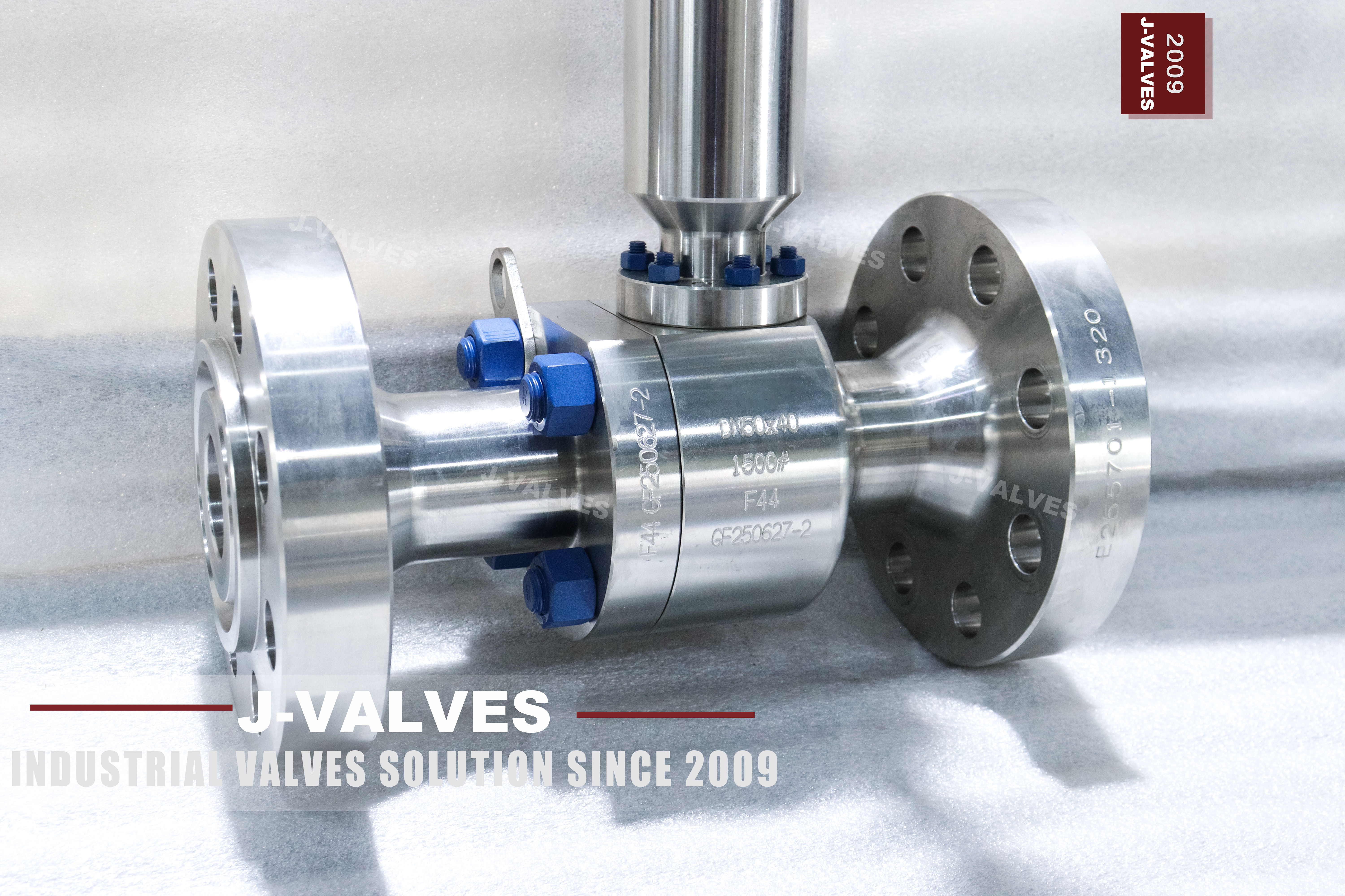
This is a two piece, flanged floating ball valve in forged F44, with a 2 inch body containing a 3/4 inch bore and a stem long enough to put the operator outside an insulation jacket. The body is ASTM A182 F44, which is UNS S31254, a super austenitic stainless with about 6 percent molybdenum and a PREN above 42. It is not a 316 valve with a better name on it; the alloy is the reason the valve exists.
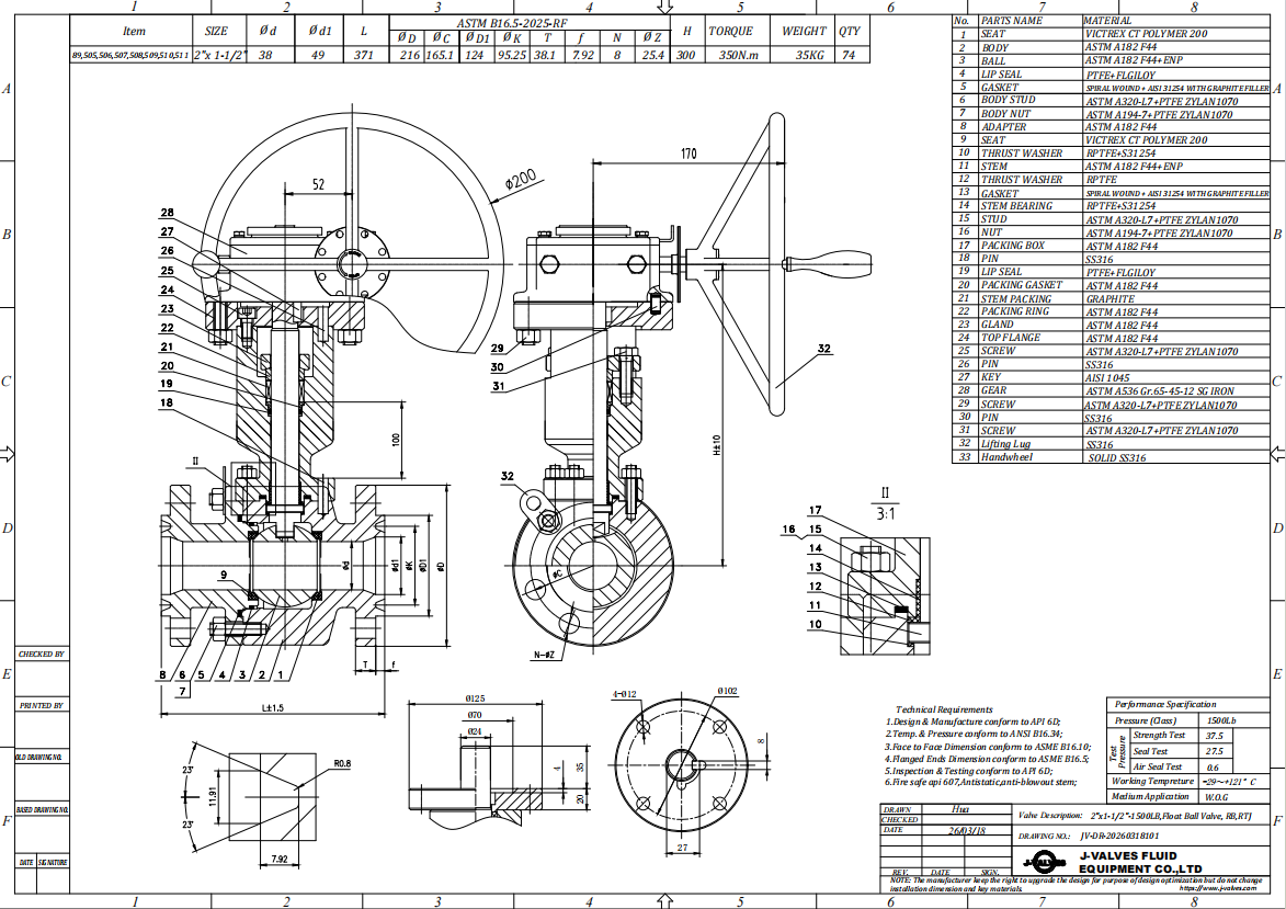
Two numbers on the original drawing need correcting and one needs explaining. The valve is Class 1500, which API 6D records as PN250, not PN260. The bore is DN20 inside a DN50 body, so the two numbers describe a body and a bore rather than two ends. And the extension is not a standard length: it is cut to the insulation thickness, which is why the drawing has to carry the dimension instead of a part number.
Design and Construction
The two piece body splits at one joint, and at Class 1500 that joint is a forged flange with ring type joint facing rather than a raised face. There is a reason: at this pressure the gasket has to be confined in a groove, because a flat gasket is pushed outward by the internal pressure faster than the bolts can hold it. The end cap sits downstream, which puts the joint on the low pressure side while the valve is closed.
The extension is the part that changes how the valve behaves. A length of tube carries the stem from the body up through the insulation, and a guide bush near the top keeps the stem from whipping when the operator turns it. The packing stays in the body where the temperature is, not at the top of the extension, so a leaking gland is still a body job and not a job at the hand wheel. What the extension moves is the operator, and only the operator.
Material Options
F44 is chosen for chloride resistance and nothing else. It holds up in sea water, brine, and process liquids that would pit 316 in months, and it does so without the nickel content of a nickel alloy. The trade is that it is harder to machine and it work hardens, so the seat pockets are cut in one pass with a sharp tool and the surface finish is inspected rather than assumed.
The ball and stem are the same alloy as the body on this build, which avoids a galvanic couple inside the valve. A 17-4PH stem is available where a harder stem is wanted, and it is a reasonable choice because the stem is not wetted over most of its length. The seat is RPTFE as standard, PEEK where the temperature or the pressure calls for it, and a hardfaced metal seat for the highest class duties.
| Component | Standard Material | Optional Upgrade | Service Notes |
|---|---|---|---|
| Main body | ASTM A182 F44 forging, UNS S31254 | None needed, F44 is already the high grade | Forged, not cast, at this class |
| End cap | ASTM A182 F44 forging | Same heat as the main body | Carries the downstream seat |
| Ball | F44, hard chrome or nitrided | Alternate hardfacing on request | Same alloy as the body avoids galvanic couple |
| Stem | F44 | 17-4PH for a harder stem | Passes through the extension to the operator |
| Stem extension | F44 tube with a guide bush | Length to the insulation thickness | Keeps the packing out of the cold or hot zone |
| Seat | RPTFE | PEEK, PPL, metal | Sets the temperature ceiling |
| Packing | High density flexible graphite | None, graphite is the standard here | Inside the body, not at the top of the extension |
| Joint gasket | Spiral wound, graphite filler | PTFE envelope is not used at this class | Single use item |
| Bolting | A193 B7 with A194 2H | B7M for sour service | Class 1500 loads are high, torque from the drawing |
| Operator | Lever at the top of the extension | Worm gear or actuator | ISO 5211 pad at the extension top |
Technical Specifications
The size line reads DN50 x DN20 because two dimensions matter: the flange is DN50 and the bore is DN20. A buyer who reads it as two different end sizes will order the wrong valve. The pressure line reads Class 1500, and the PN equivalent is 250. The code 260 appears on the original drawing and in no flange table, no API 6D clause and no EN 1092-1 row; it looks like a bar conversion of the class rating that was rounded and then treated as a designation.
The extension length is the third number on the drawing and the one most often left blank. It is measured from the body flange face to the top of the extension, it is set by the insulation thickness plus clearance for the operator, and it is not interchangeable between projects. A valve ordered without it arrives with a standard extension that fits nothing in particular.
| Item | Value |
|---|---|
| Product type | Two piece flanged floating ball valve, extended stem |
| Nominal size | DN50 x DN20, 2 x 3/4 inch, reduced bore |
| Pressure class | Class 1500 (marked 1500LB), PN250 in the API 6D designation |
| Body material | ASTM A182 F44 forged stainless, UNS S31254 |
| Body material note | F44 as stamped; no other trade name is used on this page |
| PREN | Above 42 by composition, which is the reason for the grade |
| Body construction | Two piece, one bolted joint |
| Ball | F44, hard chrome plated or nitrided |
| Stem | F44, or 17-4PH where a harder stem is wanted |
| Stem extension | Length to the insulation thickness, stated on the order |
| Extension guide | Extended bonnet with a guide bush above the packing |
| Seat | RPTFE to 180 C, PEEK to 260 C, PPL to 280 C |
| Metal seat option | F44 body with a hardfaced seat face |
| Packing | Flexible graphite, high density |
| Body joint gasket | Spiral wound, graphite filler |
| End connection | Flanged ring type joint, ASME B16.5 Class 1500 |
| Face to face | ASME B16.10, held on the drawing |
| Design standard | ASME B16.34, API 608 |
| Test standard | API 598 |
| Temperature range | -29 to 425 C body, ceiling set by the seat |
| Low temperature option | Impact tested body and extended bonnet for cryogenic and cold service |
| Media | Seawater, brine, chloride bearing process liquid, wet gas |
| Operation | Lever on the extension top |
| Operation option | Worm gear, pneumatic or electric on the extension |
| Mounting | ISO 5211 pad at the top of the extension |
| Anti static | Ball to body continuity, measured per valve |
| Fire safe | API 607 with the seat compound supplied |
| Marking | Size, class, F44 and heat number on the body |
| Traceability | EN 10204 3.1 with the heat number and the actual chemistry |
| Pressure code note | PN250 is the API 6D code for Class 1500; no PN260 exists |
Standards and Compliance
The valve is designed to ASME B16.34 for the wall and the pressure temperature rating, and to API 608 for the floating ball details: anti static path, blowout proof stem, nameplate content. ASME B16.5 supplies the Class 1500 ring type joint flange, and ASME B16.10 the face to face length, which on an extended stem valve has to be stated as the body length and the overall length separately.
API 598 governs the test, with a shell test at one and a half times the rating and a seat test at one and a time the rating in both directions. API 607 fire testing is passed on the metal shoulder behind the seat and the graphite gasket in the joint. The material certificate to EN 10204 3.1 matters more on this valve than on a carbon steel one, because F44 cannot be identified by eye or by a magnet, and the certificate chemistry is the only proof of what the body actually is.
| Requirement | Standard | What J-VALVES Supplies |
|---|---|---|
| Body wall and rating | ASME B16.34 | Forged wall at Class 1500 in austenitic material |
| Valve design and marking | API 608 | Anti static path, blowout proof stem, nameplate data |
| Flange drilling | ASME B16.5 Class 1500 | Ring type joint facing at this class, not raised face |
| Face to face | ASME B16.10 | Length on the signed drawing, including the extension |
| Pressure test | API 598 | Shell 1.5 times and seat 1.1 times the rating |
| Fire test | API 607 | Certificate against the seat compound supplied |
| Material certificate | EN 10204 3.1 | Heat number and chemistry, which is how F44 is verified |
| Pressure code | API 6D clause 7.2 | Class 1500 is PN250, stated on the drawing |
| Actuator interface | ISO 5211 | Pad at the top of the extension, drive size on the drawing |
Manufacturing Process
The body is forged rather than cast at this class, because a forging carries the wall thickness at Class 1500 without the porosity risk of a casting at the same section. The forging is solution annealed, which for a super austenitic grade is not optional: the molybdenum and nitrogen stay in solution only if the cooling is fast enough, and a slow cooled forging precipitates secondary phases at the grain boundaries and loses the corrosion resistance the grade was bought for.
Machining is slow because the alloy work hardens. The seat pockets are cut with a sharp tool and a positive feed so the cut stays under the hardened skin, and the bore is honed rather than turned where the surface finish matters. The extension is welded to the body neck and the weld is penetrant tested, because the extension passes through the pressure boundary at its base and a weld defect there is a leak that appears inside the insulation where nobody sees it.

Quality Control and Testing
The chemistry check on this valve is a grade identity check, not a specification check. F44, 316 and 904L look the same on a shelf, and a mixed charge at the forge does not show up in the finished part. Positive material identification is run on every body, and the result is read against the certificate chemistry rather than against a grade name.
The extension adds two checks that a standard valve does not have. Stem runout is measured at the top of the extension with the valve assembled, because a stem that is out by a millimetre at the body is out by several at the hand wheel and the gland leaks on one side. The extension weld is penetrant tested and the assembly is pressure tested with the extension fitted, so that the weld is proved under the same pressure it will see in service.
| Step | What Is Checked | Standard or Acceptance |
|---|---|---|
| Chemistry | Chromium, nickel, molybdenum, nitrogen for the PREN | Spectrographic analysis per heat on the 3.1 certificate |
| Grade identity | F44 against 316 or 904L on the finished body | Positive material identification on every body |
| Extension runout | Stem square to the body flange over the extension length | Dial gauge at the top of the extension |
| Shell test | Body, joint and extension joint | 1.5 times the rating, held to API 598 |
| Seat test | Both directions at Class 1500 | 1.1 times the rating, no visible leakage |
| Packing test | Stem seal at the rated pressure | No visible weep over the holding time |
| Anti static | Ball to body continuity | Measured in ohms, recorded per valve |
| Torque | Breakaway torque at the rated pressure | Measured, issued with the drawing |
| Impact test | Charpy at the stated low temperature | Only where a low temperature build is ordered |

Applications and Industry Service
The duties are sea water and brine lines, chloride bearing process liquids, wet gas, and any cold service where the valve sits inside a cold box or a thick insulation jacket. In all of them the extension is doing one of two jobs: keeping the packing out of a temperature it cannot take, or putting a hand wheel where a person can reach it without stripping insulation.
It is the wrong valve for large flow at low pressure, where a reduced bore DN20 in a DN50 body wastes most of the line capacity for no benefit. It is also wrong where the medium is clean water and the only reason for F44 would be a specification habit: the alloy costs several times a 316 body and buys nothing in a line that has no chlorides in it.

Installation, Operation and Maintenance
The valve is installed with the extension vertical or near vertical, because the guide bush is designed to take a side load at the top and a horizontal extension loads it in a direction it was not built for. The ring joint gasket is new every time the flange is broken, and the groove is inspected for a dent before the new gasket goes in, since a damaged groove will leak with a perfect gasket.
The extension has to be supported where it passes through the insulation, and the insulation itself should not be used as the support. On a cold line the extension is the part that carries frost up to the packing, and a poorly insulated extension collar is how a gland starts weeping in winter. The packing is adjusted at the body, which means the insulation collar comes off for that job and should be built to come off.
How to Specify and Order
An order for this valve has to carry six things: DN50 body with DN20 bore, Class 1500, F44 body and trim, ring type joint flanges, the extension length in millimetres measured from the flange face, and the medium with its chloride content and temperature. The extension length is the one that is always missing, and a valve built to a guessed length is a valve that has to be rebuilt.
Ask for the EN 10204 3.1 certificate with the actual chemistry, not just the grade name, plus the pressure test record, the penetrant report on the extension weld and the measured torque at the top of the extension. Spares worth ordering with the valve are a ring joint gasket, a seat pair and a set of packing rings, because those are the three items that stop an F44 valve working and all three are cheap next to a shutdown.
FAQ
Q: What is F44 in ASTM A182?
A: F44 is the ASTM A182 designation for UNS S31254, a super austenitic stainless with about 6 percent molybdenum and a PREN above 42. It is specified by the UNS number and the ASTM grade, and the certificate chemistry is what proves the body is that alloy rather than 316 or 904L, which look identical.
Q: Is Class 1500 the same as PN260?
A: No. API 6D clause 7.2 lists Class 1500 as PN250, and no flange table contains a PN260 row. The figure 260 appears to be a bar conversion of the class rating that was rounded and then written as if it were a designation; the valve is ordered and marked as Class 1500.
Q: Why is the stem extended on this valve?
A: To put the operator outside the insulation, not to move the packing. The packing stays in the body where the temperature is, and the extension carries only the stem and the hand wheel. That is why a weeping gland on this valve is still a body job rather than something adjusted at the top of the extension.
Q: How is the extension length decided?
A: It is the insulation thickness plus clearance for the operator, measured from the body flange face to the top of the extension. It is not interchangeable between projects, which is why it belongs on the drawing as a dimension rather than being left to a standard part number.
Q: Can this valve take sea water?
A: Yes. F44 with a PREN above 42 is chosen specifically for chloride bearing media, and it is the reason the valve costs more than a 316 build. The limit is temperature as much as chemistry: chloride stress corrosion resistance falls as the temperature rises, so the operating temperature belongs on the enquiry.
Q: What is the difference between DN50 and DN20 here?
A: DN50 is the flange size and DN20 is the bore. The valve is a reduced bore design, so the pipe connects at 2 inch and the flow passes through a 3/4 inch ball. Buying by the first number alone gets a valve that bolts up correctly and throttles the line.


Hot Products


News
Ball Valve Datasheet: Six Blocks That Decide Whether Two Quotes Are Comparable
A ball valve datasheet only works when six blocks are fixed: pressure basis, bore, temperature ceiling, test, end connection, operator. How each is written.
Read More
Ball Valves in Coal Gasification Black Water: Erosion, Flash And The Isolation Only Rule
The valve that stopped a gasifier train was an 8 inch Class 900 ball valve on the black water letdown, seven months into service. It had not leaked. It had stopped turning. The actuator was delivering its rated torque, the stem was intact, and the ball would not move more than a few degrees. When th
Read More
Ball Valve Sealant Injection: What The Grease Fitting Actually Connects To
A 20 inch Class 600 ball valve on a natural gas export line developed a seat leak that measured 300 parts per million by volume on the ultrasonic meter at the downstream flange. The leak was not a safety emergency and it was not going to be fixed by anything short of a shutdown, which was fourteen m
Read More
Ball Valve Condition Monitoring: Which Signals Actually Predict A Failure
Torque signatures, acoustic emission, differential pressure and digital twin residuals: which measurements find a failing ball valve early.
Read More