


CHINA J-VALVES Offers Various High-quality I ndustrial Ball Valves
J-VALVES, a distinguished professional ball valve manufacturer rooted in China, takes pride in its extensive product portfolio. Our offerings span a wide range, including trunnion-mounted ball valves, floating ball valves, high-temperature ball valves, high-pressure ball valves, metal-sealed ball valves, ultra-low temperature ball valves, DBB ball valves, Three-way And Four-way Ball Valve, and fully welded ball valves. Each product is a testament to our commitment to precision engineering and reliable performance. Meticulously crafted, they are designed to not only meet but exceed the most stringent industrial demands, ensuring stable operation even under extreme conditions. This enables us to provide our clients with high-value services and makes our valves widely sought-after in industries.
Product Category
Contact Us


Pressure Class: 600LB (PN100)
Body Material: ASTM A182 F304 / F304L / F316 / F316L (precision machined from stainless steel bar)
Temperature Range: -29℃ to +425℃
Body / Side Body: ASTM A182 F304 / F316
Ball: F304 / F316, precision lapped surface (Ra ≤ 0.4μm)
Stem: F304 / F316, high strength and corrosion resistant
Seat: RPTFE (standard) / PEEK / metal seal (optional)
Packing: PTFE V-rings / flexible graphite
Gasket: PTFE / flexible graphite / metal gasket
Handle: F304 / aluminum alloy (anodized) / nylon coated
Thread: NPT (taper pipe thread, ASME B1.20.1) / BSPT / BSPP
Socket Weld (SW): ASME B16.11 compliant, socket depth approx. 10mm
Butt Weld (BW): ASME B16.25 compliant
Flange: Optional 0.5-inch miniature flange (ASME B16.5 compliant, non-standard configuration)
Thread End Dimensions: NPT 1/2″, 14 threads per inch, thread length approx. 15mm, basic major diameter 21.224mm
Face-to-Face Dimension: Approx. 60–80mm (two-piece structure, subject to actual connection type and manufacturer data)
Operation: Manual (mini handle / needle handwheel), pneumatic (miniature rack-and-pinion), electric (miniature quarter-turn), hydraulic (miniature)
Design Standards: ASME B16.34, API 608
Test Standard: API 598
-
J-VALVES-Q41F
-
J-VALVES
Overview of the J-VALVES Half Inch Class 600 F304 Floating Ball Valve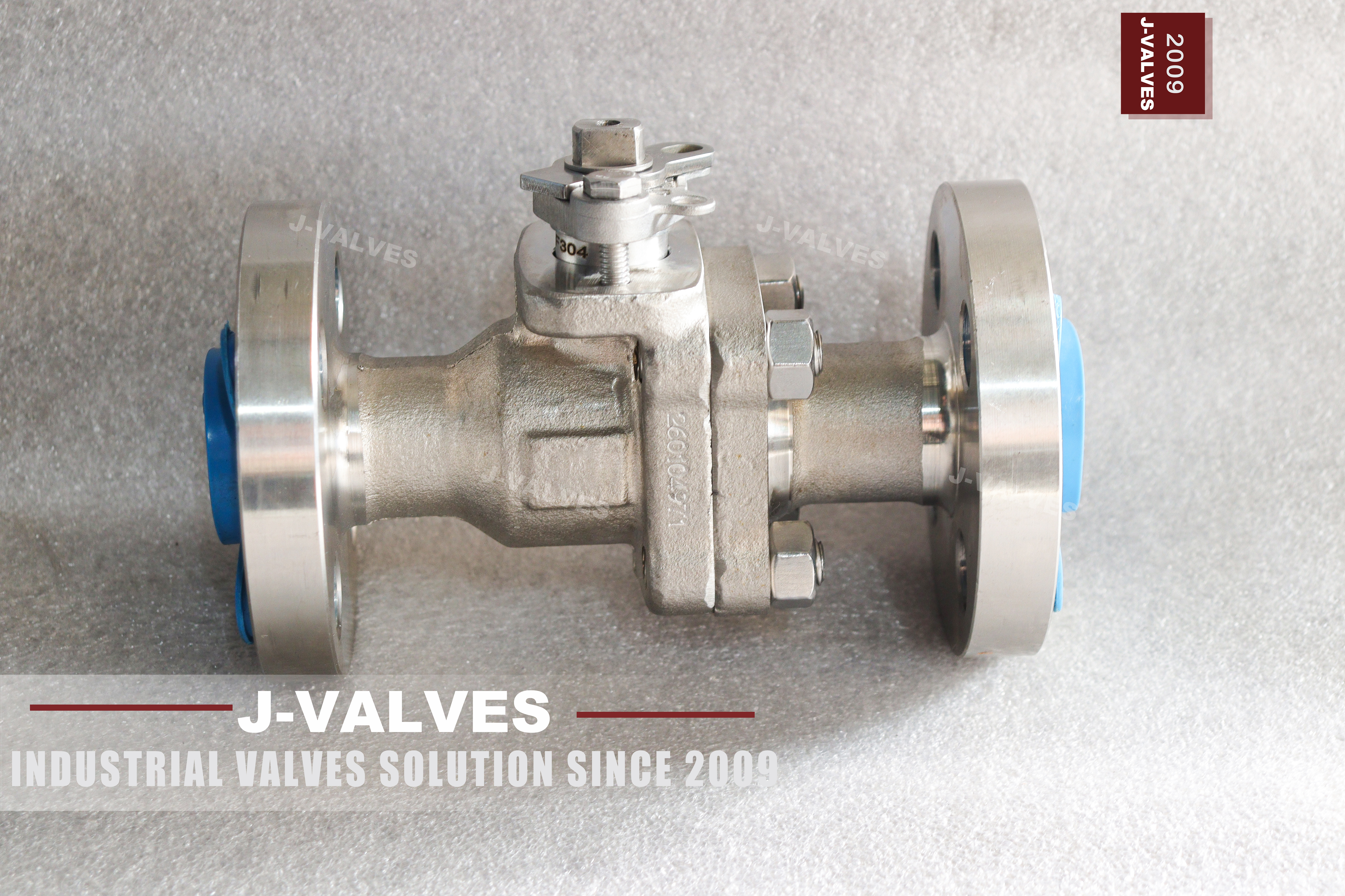
This is a half inch two piece floating ball valve machined from ASTM A182 F304 stainless bar, rated Class 600, with raised face flanges to ASME B16.5 and a bare square stem. The photograph shows the flanged version: two flanges, four bolt holes each, and a square drive above the gland with a locking hole through it. The body carries the grade and the works number in a cast or stamped panel on the side of the main body.
The original data sheet for this valve describes threaded ends as the product and a miniature flange as an option. The photograph says otherwise, and the photograph wins: this body is flanged, the flanges are machined as part of the body and the end cap, and a threaded version would be a different pattern rather than the same valve with an option ticked. That distinction is the first thing to settle on this size, because at half inch the end connection decides what the product is far more than the pressure class does.
The second thing to settle is where this valve sits inside API 608. Its flanged scope starts at DN15, which is exactly half inch, and stops at Class 600, which is exactly this rating. So this valve sits on two boundaries of the same standard at once: the smallest flanged bore it covers and the highest flanged class it covers. A valve one size smaller or one class higher leaves the scope, and that is worth knowing before a certificate is promised.
Design and Construction of the Small Two Piece Body
The body is split into a main body and one end cap with a single bolted joint. At this size the joint carries two studs rather than four, and the studs pass through lugs machined on both halves. The seal at the joint is a flat gasket in a machined recess, and the end cap is located on a spigot so that the bore stays concentric when the studs are tightened. The small number of fasteners is normal at half inch, and it is one reason the joint has to be made up evenly rather than one stud at a time.
The ball is a half inch sphere lapped to a spherical form and polished, sitting between two seat rings. In the open position the bore through the ball lines up with the body bore; a quarter turn puts the sphere across the flow and the upstream pressure pushes it onto the downstream seat. The stem is a separate part, keyed or flattened onto the ball, passing through the neck and sealed by a packing set under a gland that is bolted to the neck rather than screwed into it.
Above the gland the stem ends in a square drive with a locking hole and a travel stop plate. The lever is supplied loose. The stem is retained against blowout by a shoulder that cannot pass through the gland bore, which matters on a small valve because the stem section is thin and the pressure acting on it is the full class rating. An anti static path connects the ball to the body through the stem, as API 608 requires on a soft seated valve. The locking hole is there for a padlock or a tag, not for a bar, and a bar in that hole is the fastest way to twist a half inch stem.
| Component | Standard Material | Optional Upgrade | Service Notes |
|---|---|---|---|
| Main body and end cap | ASTM A182 F304 forged bar | F304L, F316, F316L | Machined from bar, not cast, at this size |
| Ball | A182 F304, lapped and polished | F316, hard chrome, electroless nickel | Spherical lap, matched to the seat ring |
| Stem | A182 F304 | F316, 17-4PH | Blowout proof shoulder above the gland |
| Seat | RPTFE | PTFE, PEEK, metal seat | Seat compound sets the temperature ceiling |
| Packing | PTFE V rings | Flexible graphite | Gland bolted to the neck, adjustable |
| Body gasket | PTFE | Flexible graphite, metal gasket | Flat gasket in a machined recess |
| Bolting | A193 B8 with A194 8 nuts | B8M | Stainless bolting is standard on a stainless body |
| End connection | Raised face flanged, ASME B16.5 Class 600 | NPT, BSPT, BSPP, socket weld, butt weld | Each option is a different body, not an accessory |
| Stem drive | Square with locking hole and stop plate | Lever with locking device, or a small gear | Lever supplied loose |

Material Options and Why Small Bores Are Machined From Bar
At half inch the body is not cast. A casting at this size has walls thin enough that core shift and shrinkage porosity become the dominant risk, and the seat pocket is too small to machine out a defect without cutting into the pressure boundary. Bar stock has none of those problems: the grain is uniform along the axis, ultrasonic examination is straightforward, and the seat pocket can be cut to size in solid metal. That is the real reason small stainless valves are machined rather than cast, and it has nothing to do with the grade or with the cost of a pattern.
F304 is the base austenitic grade and is right for water, steam, process fluids and most food and pharmaceutical duty. F304L is the low carbon version, chosen where the part will be welded, because the lower carbon avoids sensitisation in the heat affected zone. F316 adds molybdenum and is the grade to pick when chlorides are present, and F316L is the low carbon version of that. On a valve with threaded or welded ends the L grade matters more than on a flanged one, because the end preparation is where the heat goes.
The trim follows the body. A F304 ball running against RPTFE is the standard combination and is correct for clean service at moderate temperature. PEEK extends the ceiling, and a metal seat changes the leakage class rather than improving the seal. On this size the packing is the part that is most often skimped: PTFE V rings are standard, flexible graphite is the choice where the valve sees steam, and the gland has to be adjustable because a small packing set takes a set after a few thermal cycles.
Technical Specifications
The rows in this table are ordered so that the end connection comes before the trim, which is deliberate. On a half inch valve the end connection decides what the product is and which standard governs it, while the trim only decides how long the seat lasts. A buyer who reads the table from the bottom up will get the trim right and the ends wrong, which is the more expensive mistake of the two.
Two rows are a scope rather than a specification. The product standard row records API 608, and the scope note below it records that this bore and this class sit on the corner of the flanged scope: DN15 is the smallest flanged bore and Class 600 the highest flanged class the standard covers. That is not a marketing line, it is the reason a certificate can be issued at all, and it is the row to check first when a valve at a nearby size is quoted with the same claim.
The temperature rows are split between the body and the valve for the same reason as on any soft seated valve. The body has a ceiling from the B16.34 group 2.2 table, and the valve has a lower ceiling set by whichever seat compound was ordered. Stating one number would hide the fact that the seat gives out first, which is the single most common surprise on a small stainless valve used slightly above its intended temperature.
| Item | Value |
|---|---|
| Product type | Two piece side entry floating ball valve, soft seated, bare stem |
| Nominal size | 0.5 inch, DN15 |
| Pressure class | ASME Class 600, PN 100 by its ISO designation |
| Rating basis | ASME B16.34, material group 2.2 for F304 |
| Body material | ASTM A182 F304 forged bar, machined |
| End connection | Raised face flanged to ASME B16.5 Class 600, four holes |
| End options | NPT to B1.20.1, BSPT, BSPP, socket weld to B16.11, butt weld to B16.25 |
| End note | Each end option is a separate body pattern, not an accessory |
| Face to face | ASME B16.10 for NPS 0.5 at Class 600 |
| Bore | Full bore to API 6D Table 1 for NPS 0.5 |
| Ball | A182 F304, lapped, polished |
| Stem | A182 F304, blowout proof shoulder |
| Seat | RPTFE standard, PTFE, PEEK or metal seat on request |
| Packing | PTFE V rings, flexible graphite on request |
| Body joint | One bolted joint, two studs at this size |
| Stem drive | Square with locking hole and travel stop |
| Lever | Supplied loose, fitted at commissioning |
| Anti static | Ball to body through the stem, to API 608 |
| Fire safe | Metal shoulder behind the seat, API 607 and ISO 10497 |
| Product standard | API 608 |
| Scope note | DN15 is the smallest flanged bore and Class 600 the highest flanged class under API 608 |
| Test standard | API 598 |
| Certification | EN 10204 3.1 with the heat number and the part number |
| Temperature, body | Per ASME B16.34 group 2.2 at Class 600 |
| Temperature, valve | Set by the seat compound ordered, below the body ceiling |
Standards and Compliance
ASME B16.34 rates the body. F304 sits in material group 2.2, and the group 2.2 table at Class 600 gives the allowable pressure at each temperature. The same standard sets the minimum wall for the class and bore, and at this size the wall requirement is met by the bar diameter rather than by a separate calculation, which is one of the practical differences between a machined small valve and a cast large one. Group 2.2 is an austenitic group, and its allowable stress falls away more steeply at the top of the temperature range than a carbon steel group does, which is why a stainless valve is not automatically the better choice for a hot line even though it is the better choice for a wet one.
ASME B16.5 governs the flanges. At NPS 0.5 Class 600 the flange has four bolt holes, and the facing, bolt circle and thickness all come from the B16.5 table. The face to face length comes from B16.10, which is indexed by class rather than by nominal pressure, and that is why a valve ordered as PN 100 cannot be assumed to match a Class 600 valve on length even though the two designations correspond exactly.
API 608 governs the product and sets the scope this valve sits inside. The flanged scope runs from DN15 to DN600 at Class 150, 300 and 600; the threaded scope from DN8 to DN50 at Class 150 to 800. Half inch Class 600 is inside both, and it is at the corner of the flanged scope on both axes. Where the same valve is supplied with NPT ends it moves to the threaded scope, which reaches Class 800, so a higher class is available with threaded ends than with flanges under this standard.
| Requirement | Standard | What J-VALVES Supplies |
|---|---|---|
| Pressure temperature rating | ASME B16.34, group 2.2, Class 600 | Rated pressure at the design temperature from the group 2.2 table |
| Flange drilling and facing | ASME B16.5, Class 600, NPS 0.5 | Four holes, facing and bolt circle to the B16.5 table, measured |
| Face to face | ASME B16.10, Class 600 | Length recorded on the inspection sheet against the B16.10 table |
| Product design | API 608 | Body joint, stem retention, anti static path, fire safe shoulder |
| Threaded ends, where ordered | ASME B1.20.1 for NPT | Thread gauge check on every threaded body |
| Socket weld ends, where ordered | ASME B16.11 | Socket depth and bore checked against the fitting standard |
| Pressure testing | API 598 | Shell and seat test records, both seats, both directions |
| Material certification | EN 10204 3.1 | Heat number and part number on the certificate |
Manufacturing Process
The body starts as stainless bar, cut to length and turned. At this size the whole part is made on a lathe with milling on the same setup or in a second operation, and the critical dimensions are the bore, the seat pocket, the joint face and the flange facing. Because the part is machined from solid, the seat pocket can be cut after the bore and checked against it on the same setting, which is the accuracy a casting at this size cannot reliably deliver once the core has moved.
The ball is turned, ground and lapped. Lapping is what produces a spherical form rather than a cylindrical one, and on a half inch ball the difference shows up immediately in the seat test: a turned ball touches the seat on a band and leaks as soon as the seat relaxes, while a lapped ball touches around its whole circumference and keeps sealing as the seat takes its set. The stem is turned, the square drive is milled, and the blowout shoulder is cut as part of the stem rather than added as a collar afterwards.
Stainless parts are passivated after machining to restore the chromium oxide layer that cutting fluids and tooling disturb. Assembly is done in a clean area, with the ball and seats fitted dry first to check the float and the stem engagement, then with the gasket fitted and the two studs torqued evenly. Each valve is then marked with the size, class, grade and heat number, the flange faces are protected, and the lever is packed separately. After passivation the parts are handled with stainless or plastic tooling only, because a carbon steel clamp or a wire brush will leave free iron on the surface and the rust that follows will be blamed on the material rather than on the handling.

Quality Control and Testing
Every valve is shell tested at one and a half times the rated pressure and seat tested at one and one tenth, both to API 598, with the seat test done on each seat in each direction. On a floating valve only the downstream seat is loaded by the pressure, so a valve that passes in one direction can still leak reversed, which is why both are tested rather than one. The test medium is water with a corrosion inhibitor for a stainless body, the shell test is held for the duration API 598 sets for this size, and the valve is drained and dried afterwards so that no test water sits in the cavity during packing and shipping.
Material identity is checked by spectrometry on the body, the ball and the stem, and the result is compared against the A182 ranges for the grade ordered rather than against the mill certificate alone. On a stainless valve the substitution that matters is F304 against F316, because the two look identical and only one of them is right for a chloride bearing line, so the molybdenum reading is worth having on the record even when nobody has asked for it.
Dimensional inspection covers the bore, the face to face length, the flange bolt circle and facing, and the stem square. Where threaded ends are supplied the thread is checked with a gauge rather than by eye, and where socket weld ends are supplied the socket depth is measured, because both are joint dimensions that the customer's pipe has to match. Final inspection records the heat number against the part number, so the certificate can be traced back to one valve rather than to a batch.
| Step | What Is Checked | Standard or Acceptance |
|---|---|---|
| Bar stock | Grade and heat number against the mill certificate | ASTM A182, incoming inspection |
| Machining | Bore, seat pocket, joint face, flange facing | Works drawing |
| Ball lapping | Sphericity and surface finish | Works procedure |
| Passivation | Surface free of free iron, oxide restored | ASTM A967 where specified |
| Shell test | One and a half times rated pressure | API 598 |
| Seat test | One and one tenth rated pressure, both seats, both directions | API 598 |
| Thread, where ordered | Thread gauge, full engagement | ASME B1.20.1 |
| Dimensional and marking | Bore, length, bolt circle, stem square, marking | ASME B16.5, B16.10, API 608 |

Applications and Industry Service
Half inch Class 600 stainless belongs to instrument and sampling lines: pressure and temperature transmitter isolation, analyser sample points, gauge roots, and the small drains and vents around a skid. It is also common on steam tracing and on small utility lines where a carbon steel valve would corrode and a larger valve would not fit. The class is chosen for the line rating rather than for the flow, which is why a half inch valve at Class 600 is normal while a half inch valve at Class 150 is often enough. The reason Class 600 turns up so often on those lines is that the instrument and the manifold upstream are rated at that class, and a lower rated isolation valve would set the rating of the whole tap rather than protect it.
The stainless body is chosen where the medium would attack carbon steel: process water with chlorides, dilute acids, food and pharmaceutical service, and high purity water where a rust particle is a defect. On those duties the grade matters more than the class, and F316 or F316L is the specification rather than F304, particularly where the line is stagnant or where chlorides concentrate at a seat during evaporation. A stainless valve in a carbon steel line is also the place where a galvanic pair forms, so the flange bolting and any insulating kit belong in the same decision as the grade.
It is not the right valve for a line that carries solids, for a service where the seat has to hold with the line dry and hot above the seat ceiling, or for a location where the valve will be operated constantly. A small ball valve is an isolation device and not a control valve, and using it to throttle destroys the seat in a short time; where throttling is wanted, the valve upstream should be a globe or a needle pattern rather than a ball.

Installation, Operation and Maintenance
The flanged version is installed the same way as any small flanged valve, with the difference that the fasteners are small and easy to over tighten. The two studs at the body joint and the four at each flange are tightened evenly and in a crossing pattern, and a torque wrench is used rather than a hand feel, because at this size the gasket will be crushed before the fitter notices resistance. The flange faces are checked for parallel before the first pass, and the gasket is replaced whenever the joint is broken.
Operation is a quarter turn and the lever is fitted at commissioning rather than at delivery. The locking hole through the square drive takes a padlock or a tag, which is the reason it exists; it is not a lifting point and it is not a place to attach a cheater bar. The travel stop limits rotation, and forcing past it loads the seat rather than opening the valve further. The lever on a half inch valve is short by design, and that length is the torque limit as much as the handle is; where the valve is stiff the cause is a damaged seat or a dry packing, and a longer lever only converts that into a bent stem.
Maintenance is limited to the seat, the ball and the packing, and on a two piece body the end cap has to come off to reach them. On a flanged valve that means breaking the pipe joint on that side, which on an instrument line is usually a short job with the line already isolated. The packing can be adjusted or replaced from the top without opening the body, and on a valve that has been in steam service the packing is the item that needs attention first, because a small set takes a thermal set and then weeps at the gland.
How to Specify and Order
Six items make the order unambiguous: the size and class, the body grade with its condition, the end connection in words, the seat compound, the bolting grade, and the operator. On this size the end connection is the item most often left ambiguous, because the same nominal valve exists with flanged, threaded, socket weld and butt weld ends, and each one of them is a different body rather than an accessory fitted to a common casting.
Write the end connection as a standard and a type rather than as a word: raised face flanged to B16.5 Class 600, or NPT to B1.20.1, or socket weld to B16.11. Where a threaded end is wanted, state the thread form as well, because NPT, BSPT and BSPP are three different threads that do not interchange, and a valve supplied with one will not go into a pipe cut for another. The practical consequence is that an NPT valve will start into a BSPT socket for about two turns before it binds, which is exactly far enough for a fitter to believe it is going in, and the joint then leaks or the body splits at the neck.
Where the valve is going into an existing line, order against the measured flange or thread rather than against the class, and ask for the certificate to name the heat number that appears on the body. J-VALVES quotes from the drawing for the size, the grade and the trim ordered, and records the flange drilling and the face to face length as measured values on the inspection sheet rather than as references to a table, which is what makes a replacement valve fit a line that was built twenty years ago.
FAQ
Q: Is this valve threaded or flanged?
A: Flanged. The photographs show a body and end cap machined with integral raised face flanges, four bolt holes on each, and no threaded port. The data sheet for this item describes threaded ends first and a flange as an option, but the images and the part number are flanged, so the threaded version is a different body rather than the same valve with a different end bolted on.
Q: What does API 608 cover at half inch Class 600?
A: The flange scope of API 608 runs from DN15 to DN600 at Class 150, 300 and 600, so this valve is inside it on both counts and sits on the corner: DN15 is the smallest flanged bore and Class 600 the highest flanged class. A quarter inch flanged valve and a Class 900 flanged valve both fall outside that scope at any bore.
Q: If I order the threaded version, is the certificate the same?
A: The standard is the same but the scope is different. The threaded scope of API 608 runs from DN8 to DN50 at Class 150 to 800, so a threaded half inch valve falls into that clause instead, and the class ceiling rises with it. What does not change is the body grade, the seat options and the test procedure, which follow API 598 either way.
Q: Why is the body machined from bar instead of cast?
A: Because at half inch a casting has walls thin enough that core shift and shrinkage porosity decide whether the part passes, and the seat pocket is too small to machine a defect out without breaking into the pressure boundary. Bar stock has uniform grain, takes ultrasonic examination cleanly, and allows the seat pocket to be cut in solid metal after the bore, on the same setting.
Q: How do I know the body is F304 and not F316?
A: By the spectrometry result on the certificate, which is why the molybdenum reading is asked for rather than assumed. The two grades look identical, machine identically and are both austenitic, and only F316 is the right choice where chlorides are present. A certificate that names only stainless steel has not answered the question the line is asking.
Q: Can the valve be used for throttling on a sample line?
A: No. A ball valve is an isolation device and its seat is loaded by the ball in the closed position, so using it partly open to regulate flow erodes the seat and the ball on the downstream edge. On an analyser panel the ball valve isolates and a needle valve regulates; the two are separate items for that reason.


Hot Products


News
Ball Valve Condition Monitoring: Which Signals Actually Predict A Failure
Torque signatures, acoustic emission, differential pressure and digital twin residuals: which measurements find a failing ball valve early.
Read More
Ball Valves in SWRO Desalination: The High Pressure Section Where Ordinary Seawater Valves Fail
Why SWRO high pressure valves fail early: recovery arithmetic, crevice temperature, ERD ripple, scale, letdown cavitation and surge.
Read More
Air Test And Water Test For Ball Valves: What Each Medium Can Prove
A ball valve can pass a hydrostatic seat test and still leak gas. Why air and water prove different things, and how to read a bubble, decay or helium test.
Read More
Ball Valve Flange Bolting: Preload, Relaxation And The Fasteners That Decide Leakage
A weeping flange is rarely the gasket. Preload, torque scatter, hardness limits and thermal relaxation decide whether the joint holds at 100 bar and 400 C.
Read More