


CHINA J-VALVES Offers Various High-quality I ndustrial Ball Valves
J-VALVES, a distinguished professional ball valve manufacturer rooted in China, takes pride in its extensive product portfolio. Our offerings span a wide range, including trunnion-mounted ball valves, floating ball valves, high-temperature ball valves, high-pressure ball valves, metal-sealed ball valves, ultra-low temperature ball valves, DBB ball valves, Three-way And Four-way Ball Valve, and fully welded ball valves. Each product is a testament to our commitment to precision engineering and reliable performance. Meticulously crafted, they are designed to not only meet but exceed the most stringent industrial demands, ensuring stable operation even under extreme conditions. This enables us to provide our clients with high-value services and makes our valves widely sought-after in industries.
Product Category
Contact Us


-
J-VALVES-Q41F
-
J-VALVES
Overview of the J-VALVES 150A JIS 10K CF8 Two Piece Floating Ball Valve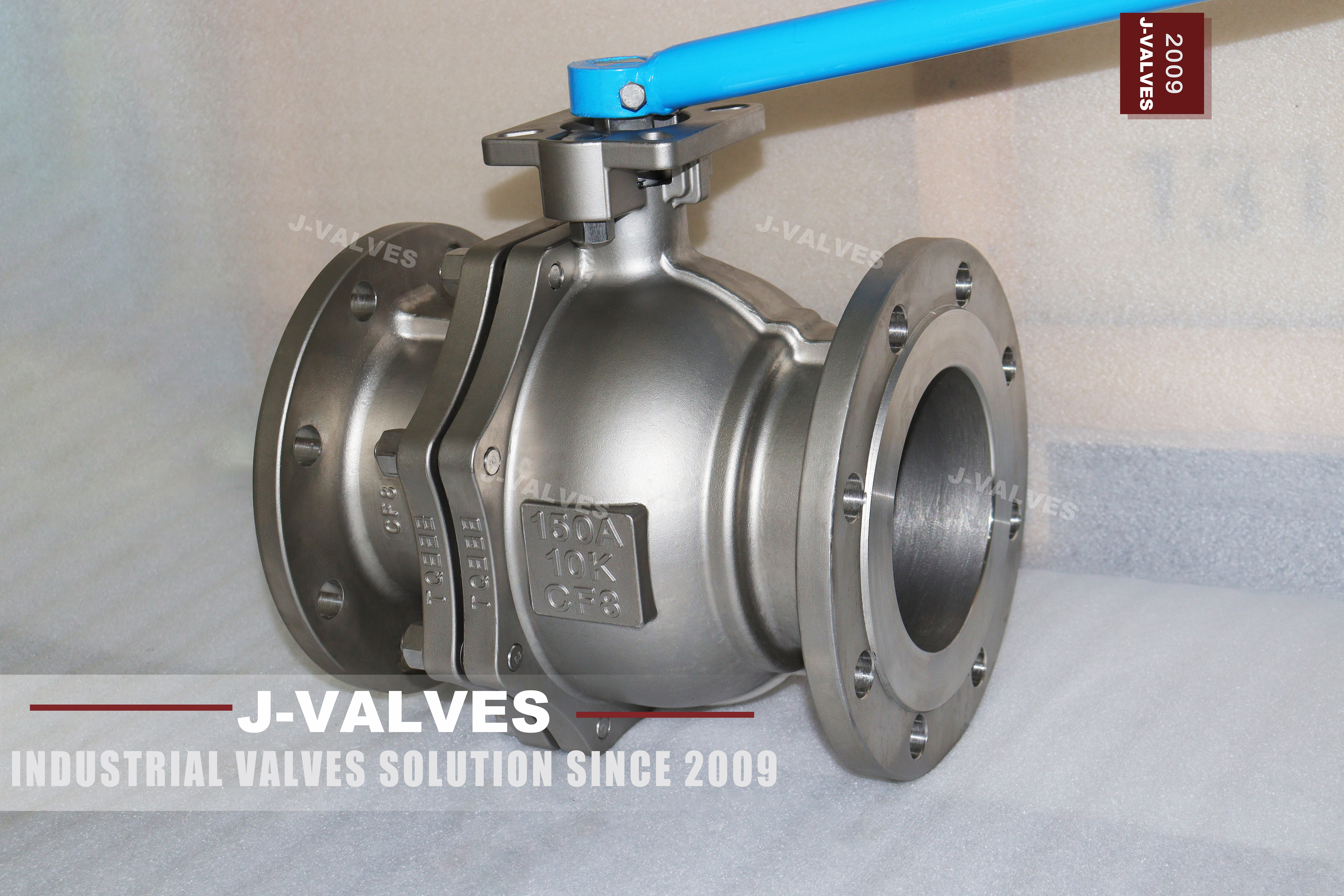
This is a six inch floating ball valve built to Japanese dimensions: a nominal size of 150A, a JIS 10K pressure classification, and a body cast in ASTM A351 CF8 austenitic stainless steel. It is a general isolation valve for water, weak chemical, food and pharmaceutical service, and it is bought by projects that were specified in the JIS system rather than the ASME one. The body is split once, into a main body and an end cap, and the ball is carried by the two seat rings rather than on trunnions.
Two designations sit on this valve and they do not mean what an ASME buyer assumes they mean. The 150A is a size only, the Japanese nominal series dimensioned in millimetres, and it happens to land on the same bore as DN150 and as six inch. The 10K is a pressure classification in which K stands for kilograms force per square centimetre, and it works out to a nominal 1.0 MPa. Neither of them is a bar value and neither of them is a pound class.
That is the first thing worth stating before any detail, because the arithmetic of the mismatch is not obvious from a drawing. A JIS 10K valve is rated at nominally 1.0 MPa. An ASME Class 150 valve in a group 2.2 material such as CF8 is rated at 19.6 bar at 38 C under ASME B16.34. The two classes differ by roughly a factor of two, while their flanges at this size are close enough that a tape measure will not separate them. Close flanges and distant ratings is the most dangerous combination in the catalogue, because the valve will fit and the installation will look right.
Three things on this page are not on the original catalogue page and are worth stating plainly before the detail. The first is the pressure basis: 10K is not 150 pounds, and on this size the difference is a factor of two rather than a rounding error. The second is that the two piece construction is not a cost decision here, it is the only construction that fits the JIS B2002 face to face dimension. The third is that a floating ball generates its own seat load from line pressure, so it seals best when the line is at pressure and worst when the line is nearly empty, which is the opposite of how most people read a leak test.
Design and Construction
The body begins as two sand castings. The main body carries one pipe flange and the stem boss; the end cap carries the other pipe flange and closes the bore behind the downstream seat. They meet on machined rims with a gasket between them and a circle of studs through both rims. The rims are machined as a pair so that the joint stays flat after both castings have been through their own shrinkage, because the two faces are only flat relative to each other.
One joint, one gasket, one set of studs: that is the whole of the pressure boundary a user can open. It is also the reason a two piece body is worth having at this size. With the line isolated and drained, the cap comes off along the pipe axis and the ball and both seat rings come out through the open end, with the pipe flanges still made up. The alternative on a JIS valve is not a welded body, it is a three piece body, and the three piece body does not fit.
The reason it does not fit is dimensional rather than commercial. JIS B2002 fixes the face to face length for a given size and class, and a three piece body has to find room inside that length for two bolted caps instead of one. On 150A there is no such room, so the two piece construction is what the standard permits rather than what the workshop prefers. Where a pipeline has already been built to JIS B2002, as it is in most plant designed to Japanese standards, this is not a preference at all; it is the only body that will go in the gap.
The ball floats. It is not carried on trunnions and nothing holds it axially, so line pressure acting on the upstream half of the ball pushes the whole ball downstream until it presses into the downstream seat. The sealing force is therefore the line pressure multiplied by the area of the seat annulus, which means the valve makes its own seat load out of the pressure it is holding. The stem turns the ball and carries no part of that load; on this design the stem is a driver, not a support.
That arrangement produces a behaviour that reads backwards to anyone used to trunnion valves. A floating ball valve seals better as pressure rises and seals worst when pressure is almost nil, because at near zero differential there is nothing to push the ball into the seat and the only available force is whatever resilience the seat ring has left. On liquid service with a few bar behind it the effect never shows. On gas at low differential, on a nitrogen blanket, on a partly drained line, or during a commissioning test held at a few tenths of a bar, it shows clearly and it is usually reported as a defective valve.

Material Options
The pressure boundary alloy is fixed by the casting. Both the main body and the end cap are cast in ASTM A351 CF8, UNS J92600, and the grade cannot be changed at the point of order without a new pattern. Everything else on the valve is a choice: the ball, the stem, the seat compound, the stem packing and the bolting are all listed as options, and an option list is not an acceptance basis. What fixes the trim is the purchase order and the EN 10204 3.1 certificate that arrives with the goods.
One combination is worth keeping out of a purchase order because it is common and it is misleading. The catalogue offers 316 for the ball and the stem, and a buyer in a hurry writes the item up as a 316 valve. The body is still CF8, so the wetted surfaces are mixed and the description is wrong at the most important place. If the service genuinely needs 316 wetted parts, the body has to be CF8M, and it should be bought and described as a CF8M valve rather than a CF8 valve with 316 trim.
The difference between the two grades is one element and a whole class of service. CF8 is the 18 chromium 8 nickel austenitic casting with no molybdenum; CF8M is the same family with molybdenum added. The absence of molybdenum is what makes CF8 a poor choice for chloride pitting and crevice attack, and it puts the grade on the correct side of the line for town water, weak acids, food contact and pharmaceutical duty, and on the wrong side for seawater, brine, hypochlorite dosing and any stream that sits wet in a chloride environment between runs.
| Component | Standard Material | Optional Upgrade | Service Notes |
|---|---|---|---|
| Body and end cap | ASTM A351 CF8, UNS J92600, cast austenitic stainless | CF8M by order, new pattern required | The alloy is cast in the mould, so a mixed pair is visible |
| Ball | CF8 with hard chrome plating | 316 stainless by order | The plating is a wear surface, not the corrosion barrier |
| Stem | 304 stainless steel | 316 stainless by order | Does not carry the seat load on a floating design |
| Seats | PTFE, reinforced PTFE, or PPL | Filled compound by order | The seat, not the body, sets the temperature limit |
| Stem packing | Flexible graphite or PTFE | Graphite where fire safety is specified | Reached from above after the lever comes off |
| Body gasket | Non metallic sheet to the JIS B2220 joint | Graphite where fire safety is specified | The one pressure boundary a user can open |
| Bolting | Metric studs matching the JIS B2220 drilling | 316 by order | Metric, not inch; this is where the ASME confusion starts |
| End connection | JIS B2220 10K raised face | Flat face or ring joint by order | Not interchangeable with ASME B16.5 at this size |
| Operation | Lever, 90 degree travel, locking hole available | Gear, pneumatic or electric on a mounting pad | The pad is a separate configuration, not a retrofit |
Technical Specifications
The table below is deliberately short on numbers, because most of the figures a buyer expects here are not figures this valve can be given from a table without inventing them. The size and the alloy come from the casting. The flange dimensions come from JIS B2220 and the face to face from JIS B2002. The pressure classification is a designation in the JIS system rather than a bar value, and the temperature ceiling is set by the seat compound rather than by the body.
Where a number is missing from this table it is because the number belongs to the drawing for the item actually ordered. Face to face in millimetres, mass, bolt circle and stud count, breakaway torque and flow coefficient all change between patterns that carry the same size callout, so a figure printed here would be a figure for some other valve. Those six values are listed again in the last section, with the document each one has to come from.
| Item | Value |
|---|---|
| Product type | Two piece side entry floating ball valve, full bore |
| Nominal size | 150A, equal to DN150 and to six inch |
| Pressure classification | JIS 10K, nominal 1.0 MPa |
| Designation basis | Japanese nominal series, dimensioned in millimetres for the size, kgf per square centimetre for the class |
| Body alloy | ASTM A351 CF8, UNS J92600, cast austenitic stainless |
| Ball | CF8 with hard chrome plating, 316 optional |
| Stem | 304 or 316 stainless steel |
| Seats | PTFE, RPTFE or PPL |
| End connection | JIS B2220 10K raised face flanged |
| Face to face | JIS B2002 |
| Body joint | One gasketed studded joint between body and end cap |
| Design standard | JIS B2071; API 608 and ASME B16.34 named as reference only |
| Inspection | JIS B2003, with API 598 for shell and seat test |
| Fire test | API 607 |
| Anti static | Conductive path from ball to stem to body, fitted as standard |
| Temperature | From -29 C; the upper limit is set by the seat compound and stated on the signed datasheet |
| Cavity port | None on this body |
| Double block and bleed | Not available on this design |
| Operation | Lever, 90 degree travel, locking hole as an option |
| Surface | Bare casting where the body is stainless, machined faces unprotected |
Standards and Compliance
The catalogue page for this valve lists JIS B2071, ASME B16.34 and API 608 together as design standards, which reads as though three standards apply at once. They do not. On a valve carrying a JIS size and a JIS class, JIS B2071 is the governing product standard, JIS B2220 governs the flange, JIS B2002 governs the face to face dimension and JIS B2003 governs inspection. The two ASME documents are references, and treating them as co-equal is how a JIS valve ends up on an ASME data sheet with an ASME pressure rating attached to it.
The rating is where the two systems separate. ASME B16.34 rates a Class 150 valve in a group 2.2 austenitic material at 19.6 bar at 38 C. A JIS 10K valve is classed at a nominal 1.0 MPa. Those are not two ways of writing the same thing; the ASME valve is rated at about twice the pressure of the JIS valve at the same temperature, and the JIS figure is a nominal classification rather than a calculated rating. Anyone who has been treating 10K and Class 150 as interchangeable has been buying a valve rated at half the line's design pressure.
The flanges make that easier to do than it should be. At 150A the JIS B2220 joint and the ASME B16.5 joint are very close in outside diameter and in bolt circle, close enough that the difference does not announce itself on a bench. What separates them in practice is the studs: JIS B2220 uses metric threads where ASME B16.5 uses inch threads, so the studs are not the same studs and a joint made up with whatever was in the store will not be either standard. The facing adds a second variable, because raised face is the default here and a flat face or a ring joint is a different item with a different lead time.
| Requirement | Standard | What J-VALVES Supplies |
|---|---|---|
| Size designation | JIS 150A, equal to DN150 and to six inch | A valve marked 150A, with DN150 carried in the data sheet |
| Pressure classification | JIS 10K, nominal 1.0 MPa | Not an ASME Class 150 valve; ASME rates that class at 19.6 bar at 38 C |
| Flange connection | JIS B2220 10K raised face | Metric studs on a metric drilling; will not interchange with ASME B16.5 inch thread |
| Face to face | JIS B2002 | A two piece body, which is the construction that meets this length at 150A |
| Product standard | JIS B2071 | API 608 and ASME B16.34 named on the sheet as reference only |
| Inspection | JIS B2003, with API 598 for shell and seat test | Reports issued against both, so either buyer can read them |
| Fire test | API 607 | A type test report covering this seat design and this size |
| Marking | Cast marks plus a name plate | Size, class and alloy on the casting; tag plate by agreement |
Manufacturing Process
Both castings are poured in CF8 to A351, and the pour is the point at which the traceability of this valve begins. The heat number follows the castings into machining and into the certificate, so the alloy a buyer reads on the test report is the alloy that was in the ladle, not a grade asserted on a plate fixed at the end of the line. On a stainless body this matters less than on a bronze or a nickel alloy one, because CF8 is a single grade rather than a family with two designations, but the chain is the same chain.
The joint rims are the section of the casting that deserves the most attention in the foundry, because they will be machined and because a shrink cavity under a machined face is not a cosmetic defect. With a gasket on one side and line pressure on the other, a porosity that reaches the surface becomes a leak path, and it will not appear until the joint is made up and tested. Feeding that rim properly and inspecting it after machining rather than before is the difference between a body that holds for twenty years and one that weeps at the joint in the first month of service.
Machining the alloy is straightforward, and the two joint rims are faced and lapped as a pair so that the gasket sits between two surfaces that are flat to each other rather than two surfaces that are each flat enough on their own. After assembly the valve is shell tested and seat tested. The finished body stays a bare stainless casting with machined faces, and no paint system is applied to it, because on an austenitic body the surface is the corrosion resistance and a coating over it adds nothing except a layer between the gasket and the joint face.

Quality Control and Testing
An A351 certificate reports two things and it is worth being clear about both. It reports the chemical composition of the heat and the mechanical properties measured on separately cast test bars. It does not describe the casting the buyer is holding, and reading a certificate more carefully does not turn a test bar result into a body result. What the certificate does give is the link between the heat number on the casting and the material that was poured, which is the part that matters when a valve has to be traceable to a specification.
The inspection sequence below is the one that catches the failures this design actually has: material mix-ups at the small parts, joint face porosity that only shows after machining, and seat damage from a ball that was turned against a dry seat. The seat test is run at 1.1 times the stated rating and the shell test at 1.5 times under API 598, with no visible leakage accepted on a soft seat, which is the criterion that matters for a thermoplastic seated valve.
| Step | What Is Checked | Standard or Acceptance |
|---|---|---|
| 1 | Chemical composition of the heat | ASTM A351 ranges for CF8, reported element by element |
| 2 | Mechanical properties | Tensile, yield and elongation on separately cast test bars |
| 3 | Casting soundness at the joint rims | Visual and dye penetrant after machining, before assembly |
| 4 | Dimensions and flange drilling | JIS B2220 10K at 150A, checked against the drawing |
| 5 | Bore and face to face | Drawing values, full bore checked with a gauge |
| 6 | Shell test | API 598, 1.5 times the stated rating, no leakage |
| 7 | Seat test | API 598, 1.1 times the stated rating, no visible leakage on a soft seat |
| 8 | Marking and traceability | Size, class and alloy read against the certificate and the test record |

Applications and Industry Service
The reason this valve exists as a distinct item rather than as a variant of an ASME valve is that a large part of the plant built in East and Southeast Asia was specified in the JIS system. Japanese domestic projects are the obvious case; the less obvious ones are the plants and vessels built to Japanese specifications outside Japan, and the water and chemical installations where the piping package came from a Japanese contractor. In all of those, 150A and 10K are the language the piping was drawn in, and an ASME valve is the thing that does not fit.
Within that world the service is ordinary. Town water and process water, weak acids and caustic solutions, food and beverage lines where a stainless body and a clean bore are the requirement, pharmaceutical service where the same two things are the requirement plus a cleaning regime, and general isolation duty on plant utility headers. The full bore helps wherever a pig or a swab has to pass, and the two piece body helps wherever a seat change has to happen without cutting the line.
Where the valve does not belong is worth stating as plainly. Chloride bearing streams are CF8M territory and not CF8, so seawater, brine and hypochlorite dosing should never be bought on this page. Low pressure gas tightness is the second exclusion, not because the valve is badly made but because a floating ball has no independent seat preload; if the duty is a gas seal at a few tenths of a bar, that requirement belongs in the enquiry in those words. And any duty that needs double block and bleed, double piston effect seats or a double barrier needs a trunnion valve, because this body has no cavity port to bleed from and no second seat barrier to offer.
The third exclusion is size growth rather than service. J-VALVES builds the floating subset of its range from half an inch to 8 inch and the trunnion subset from 2 inch to 56 inch, so 150A sits inside the floating band with two sizes of headroom above it. Whether that headroom should be used is a different question. Frequent operation, pressure sitting near the top of the 10K band, and actuation all push the decision down to six inch before the catalogue does, because all three multiply a seat load that the floating design takes out of line pressure and puts into the lever.

Installation, Operation and Maintenance
Flange make up follows the ordinary discipline plus one local rule that catches people out. The gasket is sized to the JIS B2220 joint and not to the ASME B16.5 joint at the same nominal size, the studs are metric, and they are brought up in a cross pattern in stages rather than in one pass around the circle. The local rule is that the studs are not pipe flange studs: they are a different size and a different count from the ASME equivalent, they are ordered separately, and a store that keeps only inch studs will be short at the worst moment.
The lever moves through 90 degrees and carries a locking hole as an option, which matters on a valve that is used as an isolation point rather than a control point. The stops are set at the factory and are not adjustable on the standard lever, so a valve that has been turned past its closed position hard enough to mark the seat will not be fixed by adjusting anything on top. On a floating design, over-travel and dry cycling are the two ways to damage a seat without a process upset, and both are operator behaviour rather than valve faults.
What can be done to this valve in line is the seat and ball, and only with the line isolated. The joint between body and end cap is a pressure retaining boundary held by studs, so it cannot be opened live, and there is no cavity port to vent the body through. Once isolated and drained, the cap comes off along the pipe axis, the ball and both seats come out, and the gasket and the cap studs are replaced on reassembly. The cap face is checked for flatness before the joint is closed, because a face that has been opened several times and pulled down unevenly is the most common source of a joint weep that gets blamed on the seat.
One workshop habit is worth more on this valve than on a carbon steel one. The shell and seat tests are run with water, and a body with no drain plug keeps that water in the cavity when the test is over. Left there, it sits against the gasket edge, which is a crevice, and it is the first place a chloride stain will appear. Flush with fresh water, blow the cavity out through the bore with the ball half open, and cap the flanges. It takes a minute at the test bench and it removes the most common reason a stainless valve arrives at site with something inside it.
How to Specify and Order
An order for this valve has to carry the things the casting does not. The casting fixes the size callout, the class and the body alloy. It says nothing about the seat compound, the trim, the gasket, the stud grade or the facing. So the specification should name the body as ASTM A351 CF8 by UNS number, name the seat compound and its supplier grade, name the ball and stem material separately rather than describing the valve as 316, name the facing as raised face or otherwise, and name the stud grade with the temperature it is rated for.
The flange clause deserves its own sentence, because it is the clause most often copied from an ASME data sheet. It should read that the flanges are to JIS B2220, Class 10K, at nominal size 150A, raised face, with metric studs, and that the valve is not offered as an ASME B16.5 Class 150 item. A supplier who can answer that clause has understood which standard the valve is built to. A supplier who answers with a pressure class in pounds has not.
The last six items are the ones that change the price and the fit, and every one of them belongs on the drawing rather than on this page. Face to face in millimetres, flange drilling including bolt size, count and pitch circle, mass, seat compound and its pressure temperature curve, ball and stem material against a 3.1 certificate, and the actuation interface if the valve is to be automated. A quotation that omits them cannot be compared with another supplier's on anything except unit price, which is the one number that says least about the valve. Where automation is planned, the mounting pad has to be in the original order, because it is a different top works and not a retrofit; J-VALVES supplies a JIS 10K variant with an ISO 5211 pad as a separate item.
FAQ
Q: Is a JIS 10K valve the same as an ASME Class 150 valve?
A: No, and the difference is a factor of two rather than a rounding. 10K is a Japanese classification in which K stands for kilogram force per square centimetre, so it works out to a nominal 1.0 MPa. ASME B16.34 rates a Class 150 valve in a group 2.2 material such as CF8 at 19.6 bar at 38 C. The flanges at 150A are close enough in diameter and bolt circle to be confused, but the studs are metric on the JIS joint and inch on the ASME joint, so the two will not interchange either.
Q: What is the temperature limit of this valve?
A: The upper limit is set by the seat compound and has to come from the pressure temperature curve of that compound at the 10K classification, supplied for the material actually fitted. The body is not the limit here. What can be said with certainty is that a thermoplastic seat cannot reach the figure in the four hundreds of degrees that appears on soft seated pages, because PTFE, RPTFE and PPL all take a compression set well before that and stop sealing at the next thermal cycle.
Q: Can the seats be changed with the valve still in the line?
A: The seats and the ball can be reached without cutting the pipe, but not without isolating the line. The joint between body and end cap is a pressure retaining boundary held by studs, and this body has no cavity port to vent, so the line has to be isolated and drained first. After that the cap comes off along the pipe axis and the ball and both seat rings come out through the open end, with the pipe flanges still made up. The gasket and the cap studs are replaced on reassembly.
Q: Why does the valve leak at low pressure and seal at high pressure?
A: Because a floating ball makes its own seat load. There are no trunnions and nothing holds the ball axially, so line pressure pushes the ball into the downstream seat and the sealing force is that pressure multiplied by the seat annulus area. At a differential of a few tenths of a bar there is almost nothing to push with, and sealing depends on the resilience left in the seat ring. This is normal for the design and it is the reason a gas tightness requirement has to be stated in the enquiry rather than inferred from the pressure class.
Q: When should this be a trunnion mounted valve instead?
A: When the torque or the cycle count stops being reasonable for a lever, or when the duty needs double block and bleed, double piston effect seats or a double barrier. A floating ball has none of those features because there is no cavity port to bleed from and no independent seat preload. A trunnion design carries the ball on bearings and preloads the seats independently of line pressure, which is what makes the larger sizes and the actuated duties workable.


Hot Products


News
Ball Valve Condition Monitoring: Which Signals Actually Predict A Failure
Torque signatures, acoustic emission, differential pressure and digital twin residuals: which measurements find a failing ball valve early.
Read More
Ball Valves in SWRO Desalination: The High Pressure Section Where Ordinary Seawater Valves Fail
Why SWRO high pressure valves fail early: recovery arithmetic, crevice temperature, ERD ripple, scale, letdown cavitation and surge.
Read More
Air Test And Water Test For Ball Valves: What Each Medium Can Prove
A ball valve can pass a hydrostatic seat test and still leak gas. Why air and water prove different things, and how to read a bubble, decay or helium test.
Read More
Ball Valve Flange Bolting: Preload, Relaxation And The Fasteners That Decide Leakage
A weeping flange is rarely the gasket. Preload, torque scatter, hardness limits and thermal relaxation decide whether the joint holds at 100 bar and 400 C.
Read More