


CHINA J-VALVES Offers Various High-quality I ndustrial Ball Valves
J-VALVES, a distinguished professional ball valve manufacturer rooted in China, takes pride in its extensive product portfolio. Our offerings span a wide range, including trunnion-mounted ball valves, floating ball valves, high-temperature ball valves, high-pressure ball valves, metal-sealed ball valves, ultra-low temperature ball valves, DBB ball valves, Three-way And Four-way Ball Valve, and fully welded ball valves. Each product is a testament to our commitment to precision engineering and reliable performance. Meticulously crafted, they are designed to not only meet but exceed the most stringent industrial demands, ensuring stable operation even under extreme conditions. This enables us to provide our clients with high-value services and makes our valves widely sought-after in industries.
Product Category
Contact Us


-
J-VALVES-Q41F
-
J-VALVES
Overview of the J-VALVES One by Three Quarter Inch PN20 Forged Carbon Steel Two Piece Floating Ball Valve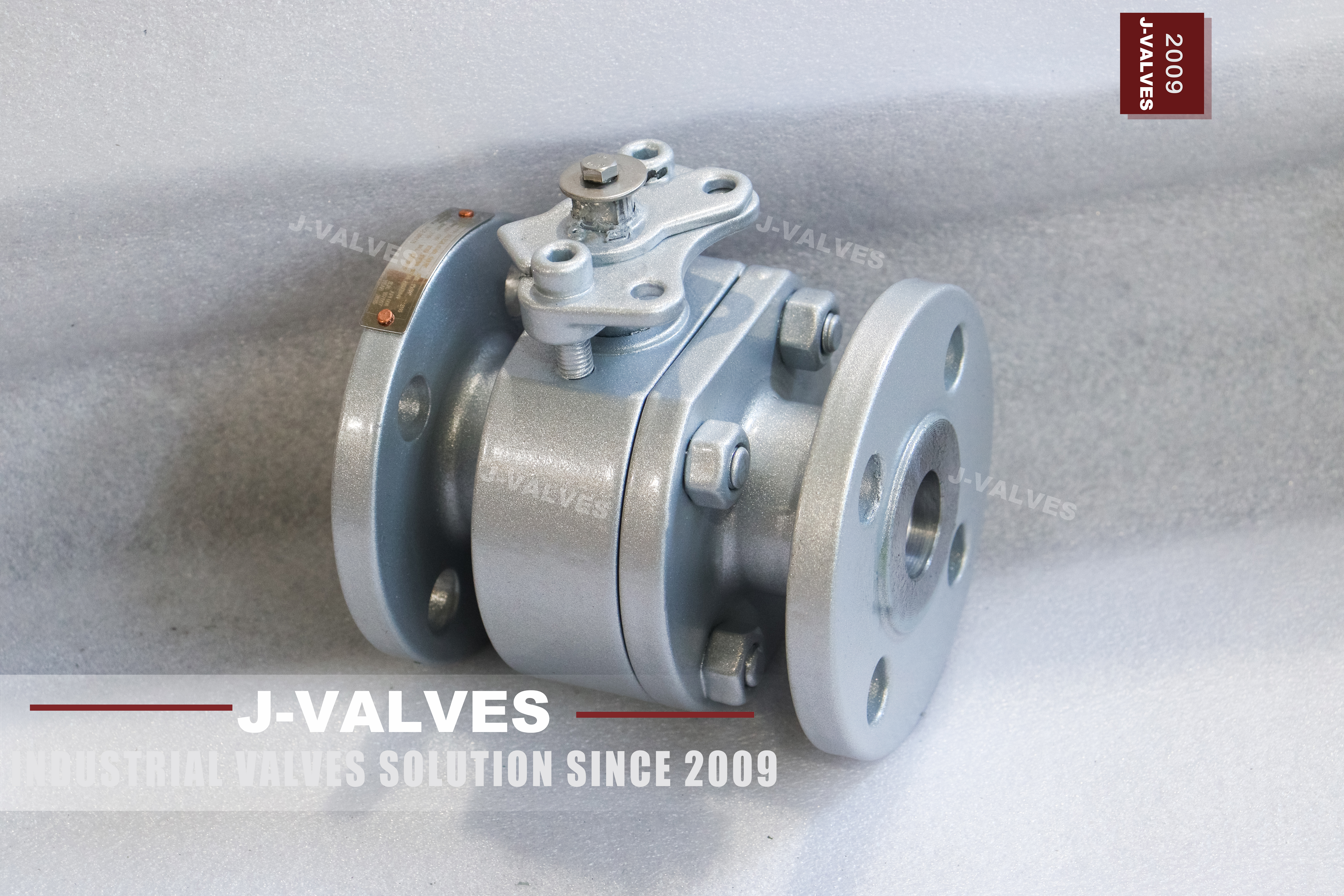
This is a two piece side entry floating ball valve in forged A105N carbon steel, one inch by three quarter inch at Class 150, flanged raised face and lever operated. The body is painted, the joint is a single ring of studs and nuts, and the stem leaves through a gland at the neck with a clamped lever boss above it. The designation carries two diameters. Both ends are DN25; the bore through the ball is DN20.
The flanges, the face to face length and the lever are all one inch, which is why the second number is so often quoted as if it were the valve size and then used to order gaskets and a spool piece of the wrong length. The data sheet on the original page is twelve lines long, and six of those lines are the ones that decide what actually arrives. Seat material, stem material, bolting, coating system, operator interface and face to face length are either missing or stated as a list of options. This page is mostly about closing those six gaps, because that is where the arguments after delivery come from.
Valves at this size are usually bought in numbers rather than one at a time, and that changes what the paperwork has to do. A box of ten may contain three heats, and if the certificate lists one, the other two are unaccounted for the moment the boxes are opened. Ask for the heat numbers to be listed against the quantity supplied, and for the marking on each body to match. It costs nothing at the order stage and it is the difference between a traceable stock and a shelf of valves nobody can identify two years later.
Design and Construction
One joint, one gasket, one ring of studs. The cap is a spigot that enters the body, so the ball and both seats leave through that end and the cap has to travel along the pipe axis before it clears. On a small valve that is a bench job; on a line it means opening the pipe at that point. The bore is reduced by one nominal step, from DN25 ends to DN20 through the ball. Nothing outside the flow path changes: the same flange drilling, the same face to face, the same lever.
What changes is the flow area, and with it the pressure drop at any given flow, permanently and without any way to convert the valve back to full bore later. The stem sits in a gland at the neck with a clamped lever boss on top, and there is no mounting pad and no cavity drain on this body. The absence of the pad is the fact most often discovered late, because a valve that is going to be automated needs either a pad or a bracket, and a bracket on a lever boss is not the same thing as a machined interface.
That axial movement is a fact about the pipe as much as about the valve. A spool piece that is too short, or a flange pair pulled together against spring, leaves no room for the cap to move back, and the seat change that looked like a bench job becomes a pipe cut. On a small line the spring in the pipe is often enough to hide the problem at installation and to reveal it at the first maintenance, when the joint is opened and the cap will not come free.
Material Options
The body is forged A105N, normalised, and painted. On carbon steel, paint is a corrosion system rather than a cover up, so the question is not whether it should be there but what it is and how thick, and whether the flange faces were masked before it went on. Two of these rows are decided by the buyer rather than by the supplier. A carbon steel ball with hard chrome and a solid stainless ball look identical in a photograph and behave very differently once the coating is breached, and the grade will only ever be on the certificate.
The same is true of the stem, which is the one part of this valve nobody can inspect after assembly. The gasket under a raised face is a decision that otherwise gets made by whoever packs the box. A spiral wound gasket with a graphite filler is the general purpose answer and needs a defined compression to work; a PTFE envelope gasket is for clean duty and seals at much lower load, which is why it is common on instrument air and rare on anything that cycles. Neither is wrong, but the two need different bolt loads, and a joint closed to a figure chosen for the other gasket will either weep or crush the sheet.
The bolting is where a carbon steel valve quietly becomes a corrosion problem. A193 B7 studs with A194 2H nuts are the standard pairing and they are carbon steel, so on a coastal site or in a chemical atmosphere they are the first parts to go. A stainless alternative puts a dissimilar metal into a carbon joint and trades general corrosion for a galvanic couple at the threads. The honest answer is to pick what suits the site and write the reason down, rather than to accept whatever the works has in the bin.
| Component | Standard Material | Optional Upgrade | Service Notes |
|---|---|---|---|
| Body and end cap | ASTM A105N forging, normalised | A216 WCB casting for the same rating | A105 and WCB share one material group and one set of ratings |
| Ball | A105N with hard chrome | Solid 316 stainless | A coated carbon ball and a solid stainless ball are different valves in five years |
| Stem | 316 stainless | A105N with surface treatment | The stem grade is inside the packing and cannot be seen |
| Seat | PTFE | RPTFE, PPL, or metal seat on request | The seat, not the body, sets the upper temperature |
| Packing | PTFE V rings | Flexible graphite | Standard for water and air, graphite for higher temperature |
| Gasket | Spiral wound, graphite filled | PTFE envelope for clean duty | One joint only, at the end cap |
| Bolting | A193 B7 with A194 2H nuts | B8M with 8M nuts | B8M on a carbon body puts stainless into a carbon joint |
| Coating | Epoxy, shop applied | Colour to the project specification | Flange faces and stud threads must stay bare |
Technical Specifications
The ratings below are table values for the material group of this body. Class 150 in group 1.1 reads 285 psi at 38 C, and the group is what makes A105 and WCB interchangeable on paper. The temperature line needs one warning attached. Group 1.1 allows the body to run to 425 C, but a PTFE seat is a long way below that, and saturated steam at this class sits close enough to the seat ceiling that the choice of seat becomes the deciding question. A valve ordered for steam with a standard seat is a valve that will be back within a year.
The coating is a system with a sequence, and the sequence is what fails when a valve rusts in storage. Blast, prime, finish coat, with the raised faces and the stud threads masked before any of it goes on. Dry film thickness is the number that decides whether the system works and it is measured rather than assumed. Colour is a separate question and usually a plant standard; on a utility line it exists so a fitter can tell air from water at a glance, which is a safety function rather than decoration.
Storage is part of the specification whether it is written down or not. A painted carbon valve that sits outdoors with the flange protectors off will have rust on the raised faces before it is installed, and the rust will be blamed on the paint. Keep the protectors on until the moment of installation, store under cover where the site allows it, and touch up the film where a sling or a spanner has cut through. None of that is technical, and all of it decides what the joint looks like six months later.
| Item | Value |
|---|---|
| Type | Two piece side entry floating ball valve, soft seated |
| Nominal size | 1 x 3/4 inch, DN25 ends by DN20 bore |
| Pressure class | Class 150, stamped 150LB on the body |
| Pressure designation | PN 20, the designation API 6D clause 7.2 writes against Class 150 |
| Shell rating | 285 psi (19.6 bar) at 38 C, ASME B16.34 group 1.1 |
| Body material | ASTM A105N forging, normalised |
| Bore | Reduced, one nominal step below the end size |
| End connection | Raised face flanged to ASME B16.5, Class 150 |
| Face to face | ASME B16.10 for the size and class, unchanged by the bore |
| Packing location | Gland at the body neck |
| Operator | Lever with clamped boss, locking hole available |
| Mounting pad | Not part of this body |
| Cavity drain | Not part of this body |
| Temperature, body | Group 1.1, minus 29 C to 425 C |
| Temperature, valve | Set by the seat ordered, not by the body |
| Product standard | ASME B16.34 and API 608 |
| Test standard | API 598 |
| Fire test | API 607 and ISO 10497 when specified |
Standards and Compliance
API 608 applies here without any argument. Its flanged scope runs from DN15 to DN600 at Class 150, 300 and 600, and this valve is DN25 at Class 150, which is squarely inside it. That is worth saying because the same sentence would be wrong on a high pressure page. The certification row carries the whole argument of this page. A data sheet that says normalised and a certificate that says nothing about heat treatment describe two different objects, and once the valve is painted there is no second chance to tell them apart. Write the condition into the purchase order and check that the certificate repeats it.
The material group is what makes a carbon valve interchangeable with a cast one, and it is also what makes it not interchangeable with a stainless one. A105 and A216 WCB sit in one group and carry one set of ratings, so the choice between them is about shape and availability rather than performance. An austenitic body of the same class sits in a different group with its own figures. That is the reason a line cannot simply swap one for the other on the strength of the class stamp alone, whatever the two valves look like from outside.
Nothing on this page quotes a flow coefficient, and that is deliberate rather than an omission. The figure depends on the bore, the seat type, the travel and the test method, and a number published against a generic valve is a number that will be used to size a pump it was never measured for. What can be stated without a test is the geometry: the bore is one nominal step below the end size and the pressure drop follows from that. Anything beyond it belongs on a test sheet for the specific valve.
| Requirement | Standard | What J-VALVES Supplies |
|---|---|---|
| Pressure boundary design | ASME B16.34 | Wall thickness and material group stated on the drawing |
| Product standard | API 608 | Anti static device, fire safe design, marking to the standard |
| Pressure testing | API 598 | Shell at 1.5 times rating, seat at 1.1 times rating |
| Fire qualification | API 607 and ISO 10497 | Certificate covering the size and class band ordered |
| Flange drilling | ASME B16.5 | Raised face Class 150, bare face before coating |
| Face to face | ASME B16.10 | Length per the table for the size and class |
| Material certification | EN 10204 3.1 | Heat number, grade, and the normalised condition named |
| Marking | API 608 and ASME B16.34 | Size, class, grade and heat number on the body |
Manufacturing Process
The forging is normalised after forming, which is what the N in A105N means, and then machined in one setup for the bore, the joint face and the seat pocket so those three stay concentric. The cap is machined to match and fitted with its gasket before the ball is finally positioned. Surface preparation is the step that separates a valve that lasts from one that rusts at the flange in a year. Blasting and a primer coat happen before assembly, because the bore has to be clean and dry before the ball and the seats go in.
The finish coat goes on after the test, with the flange faces and the stud threads masked, and it is cured to the thickness written on the order. A painted raised face is a gasket sitting on paint, and paint creeps under load. The order of assembly and test is what makes the test result mean something. The body is assembled and pressure tested before the finish coat is applied, because a test that opens the joint would damage a film that has already been cured. Between those two steps the valve is turned through its full quarter by hand and the gland is checked for drag. The lever is fitted after the test, so that the boss is never used as a handling point.
A valve painted before its test has a record and no way to touch up what the test did to the paint. The ball is ground and then lapped against its seat rather than against a nominal size, because the seal is a band of contact rather than a line. A ball that is round but not matched will seal at assembly and weep after a thermal cycle, as the polymer creeps and the band moves. That matching is a bench operation with no certificate attached to it, which is why two valves built to the same drawing can behave differently in service and why the workshop matters as much as the specification.

Quality Control and Testing
The test sequence is short because the valve is small, and the two steps that get skipped on cheap versions are the two that matter: the coating inspection and the identity check on the trim. The coating step is not cosmetic on a carbon steel valve. A holiday in the film at a flange or under a nut is where corrosion starts, and it starts where nobody looks until the joint is opened.
Ask for the dry film thickness and the holiday test on the record rather than a colour number in a catalogue. The dimensional record on a valve this size is short and belongs with the test sheet rather than in a project file. Face to face, bore, facing and bolt pattern are the four numbers that decide whether the valve will fit, and all four are cheap to measure and expensive to discover wrong on site.
Photographing the stamping beside the measuring instrument costs nothing and settles the identity question at the same time. The first line of the record decides the rest, and it is checked at goods in rather than at the end. A105N is a normalising condition rather than a grade name, so the certificate has to state it beside the chemistry; a certificate that lists A105 alone has described a different product. That check has to happen before the bar is cut, because once the valve is machined no inspection can put the heat treatment back.
| Step | What Is Checked | Standard or Acceptance |
|---|---|---|
| 1 Incoming material | Grade, product form, normalised condition | A105N forging, certificate matches the stamping |
| 2 Dimensional | Bore, end sizes, face to face, joint face | Drawing and ASME B16.10 for the class |
| 3 Machining | Seat pocket concentricity, gland bore, stem fit | In house tolerance on the signed drawing |
| 4 Coating | Thickness, adhesion, holidays, masked faces | Dry film thickness and holiday test per the order |
| 5 Shell test | Body and joint under pressure | API 598, 1.5 times rating, no leakage |
| 6 Seat test | Both seats, both directions | API 598, 1.1 times rating, no visible leakage |
| 7 Operating test | Quarter turn, lever stop, gland tightness | Full travel without binding at either stop |
| 8 Marking and records | Stamping, heat traceability, test record | Certificate and test sheet issued with the valve |

Applications and Industry Service
The normal duty is water, air, and low pressure utility service on lines where a one inch isolation point is needed and the pipe is one inch. Cooling water branches, instrument air, plant air, wash down and small process connections are all the same problem, and the reduced bore costs nothing that this duty cares about. Steam is the case that needs a decision rather than a default. At this class saturated steam sits close to the ceiling of a PTFE seat, so the seat has to be chosen for the temperature and not for the price. A PPL or metal seat solves it; ordering the standard seat and hoping does not. What it should not be used for is throttling, and it should not be installed on any line that may later be pigged.
A reduced bore valve will not pass a pig, and a soft seated valve used as a control valve will be destroyed by the flow rather than by the pressure. The case against a reduced bore on a utility header is velocity rather than pressure. The same flow through a smaller port moves faster, and faster flow erodes a soft seat and makes noise at the point where the valve is nearly closed. On a branch that runs a few hours a week that is irrelevant. On a line that is the only path for a large flow it becomes the reason to buy full bore, and at one inch the price difference is small enough that the decision should be made on the duty rather than on the quotation.
Instrument air is the duty where a small carbon valve is most often taken for granted and most often the cause of a problem. Compressor oil and moisture leave a film on the seat, and a soft seat that has been sitting closed for a year with that film on it will stick before it will leak. The cure is a quarter turn every so often rather than a different valve, and the specification point is that the seat material should suit the air quality rather than the pressure, which on an instrument line is never the issue.

Installation, Operation and Maintenance
Install in any orientation with the lever clear of structure, and leave room for the lever to swing through ninety degrees. Keep the flange faces bare and the stud threads clean, and do not paint over either after installation; that is the single most common cause of a joint that will not seal and cannot be explained. Tighten the flange bolts in a cross pattern to the gasket manufacturer's figures rather than to feel. On a small valve it is easy to over tighten one side, which distorts the body joint face and produces a leak that looks like a gasket fault. Support the pipe on both sides rather than using the valve as a pipe support.
Operation is a quarter turn with hard stops. For maintenance, isolate and vent the line, open the valve and drain the cavity, then remove the cap. Renew the body gasket rather than reusing it, and check the seat faces for wire drawing if the valve has been used to throttle. A scored seat will not reseal by tightening anything. The lever is a wear item on a small valve in a way that it is not on a large one, because it is operated by hand and it gets used as a handle for the pipe. A clamped boss with hard stops takes the load off the stem when somebody leans on it, and the locking hole is what makes a lockout physical rather than procedural.
Both are cheap at the order stage and awkward to add later, which is why they belong in the specification rather than in a conversation after delivery. The spare parts list for a valve this size is three items and one of them is a consumable. The body joint gasket is single use and cannot be reused after the joint has been opened, whatever the workshop practice is. The seat set is replaced rather than refaced when it has been scored. The packing set is renewed whenever the gland has been disturbed. Keeping one of each per valve in critical service costs very little and turns a seat change into an afternoon rather than a purchase order with a lead time attached to it.
How to Specify and Order
The order should close the six gaps in the original sheet. Seat material, with the temperature it is expected to see. Ball and stem material, named separately, because one is coated and the other may not be. Bolting grade, since B8M in a carbon joint is a decision rather than a default. Coating system, with thickness and the instruction that flange faces stay bare. Operator interface, because this body has no mounting pad and adding one later is not a field operation. And the face to face length, which follows the one inch size and not the three quarter inch bore.
Ask for the EN 10204 3.1 certificate with the normalised condition stated, the API 598 test record, and the fire certificate if the line needs one. On a valve at this price the paperwork costs more than the machining, which is exactly why it is the part that gets dropped when nobody asks for it. The pressure test is short on a valve this size, and it is tempting to treat the record as a formality. It is not, because the test is the only point at which the two seats are checked independently.
A floating ball loads one seat in service, so a seat that leaks upstream never shows itself on the line; the valve is judged tight for years and then fails the first time the flow reverses. Ask for both directions on the record, with the pressure and the hold time written beside each, and for the works number to appear on the same sheet as the readings. A test sheet that cannot be tied to the valve in the crate is a sheet about some valve.
FAQ
Q: Why does this valve have no mounting pad?
A: Because the body is a lever version. There is no machined actuator interface, so automation needs a bracket kit or a different body. If the line may be automated later, order the padded body now rather than adding a bracket afterwards.
Q: Is A105N different from A105?
A: The N means normalised. The chemistry and the ratings are the same, but the heat treatment has to appear on the certificate, otherwise a normalised data sheet and an as forged certificate describe two different objects.
Q: What does 1 x 0.75 inch mean?
A: Both ends are DN25 and the bore through the ball is DN20. The flanges, the face to face length and the lever are sized for one inch, so gaskets and spool pieces are ordered for DN25 rather than DN20.
Q: Why is the valve painted if it is forged?
A: Because it is carbon steel. Paint is the corrosion system, and the only rule is that the raised faces and the stud threads stay bare. A painted flange face is a gasket sitting on a compressible film.
Q: Can it be used on steam?
A: Only with the right seat. A PTFE seat is far below the body rating, so steam duty needs PPL or a metal seat, and the temperature has to be stated in the enquiry rather than assumed from the class.
Q: Can this valve do double block and bleed?
A: No. A floating ball only loads the downstream seat and there is no cavity drain on this body, so there is nothing to bleed and no second barrier to verify. Double block and bleed needs a trunnion valve with the right seat.


Hot Products


News
Ball Valve Condition Monitoring: Which Signals Actually Predict A Failure
Torque signatures, acoustic emission, differential pressure and digital twin residuals: which measurements find a failing ball valve early.
Read More
Ball Valves in SWRO Desalination: The High Pressure Section Where Ordinary Seawater Valves Fail
Why SWRO high pressure valves fail early: recovery arithmetic, crevice temperature, ERD ripple, scale, letdown cavitation and surge.
Read More
Air Test And Water Test For Ball Valves: What Each Medium Can Prove
A ball valve can pass a hydrostatic seat test and still leak gas. Why air and water prove different things, and how to read a bubble, decay or helium test.
Read More
Ball Valve Flange Bolting: Preload, Relaxation And The Fasteners That Decide Leakage
A weeping flange is rarely the gasket. Preload, torque scatter, hardness limits and thermal relaxation decide whether the joint holds at 100 bar and 400 C.
Read More