


CHINA J-VALVES Offers Various High-quality I ndustrial Ball Valves
J-VALVES, a distinguished professional ball valve manufacturer rooted in China, takes pride in its extensive product portfolio. Our offerings span a wide range, including trunnion-mounted ball valves, floating ball valves, high-temperature ball valves, high-pressure ball valves, metal-sealed ball valves, ultra-low temperature ball valves, DBB ball valves, Three-way And Four-way Ball Valve, and fully welded ball valves. Each product is a testament to our commitment to precision engineering and reliable performance. Meticulously crafted, they are designed to not only meet but exceed the most stringent industrial demands, ensuring stable operation even under extreme conditions. This enables us to provide our clients with high-value services and makes our valves widely sought-after in industries.
Product Category
Contact Us


-
J-VALVES-Q41F
-
J-VALVES
Overview of the J-VALVES 3/4 x 1/2 Inch PN20 Forged F316 Two Piece Floating Ball Valve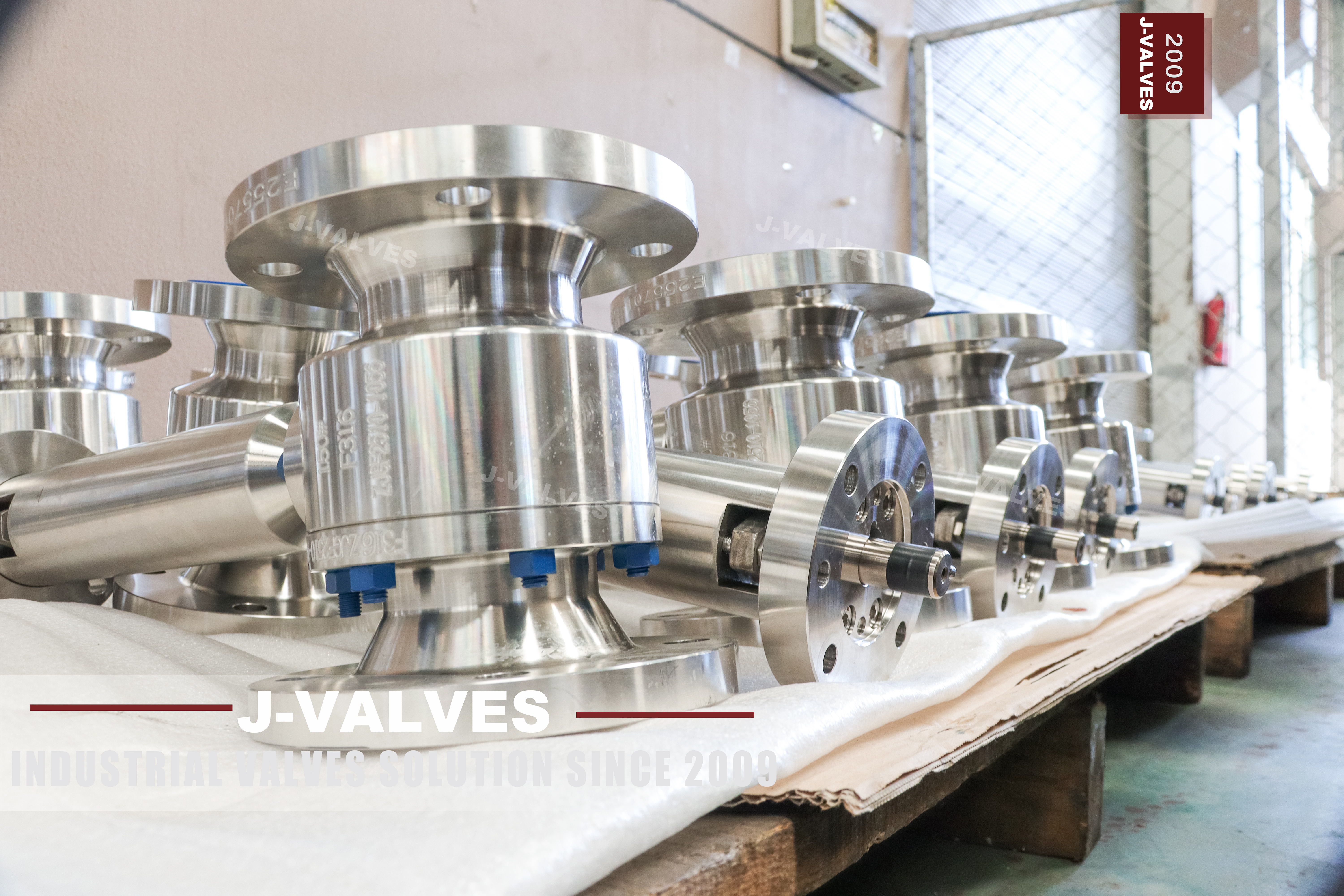
This is a two piece side entry floating ball valve with a forged A182 F316 body, a solid F316 ball and a bare extended stem, built at 3/4 x 1/2 inch for Class 150 service. The body carries five lines of stamping: the size, 150LB, F316, a works number and a heat number. The end cap carries F316 and the same works number, so the pressure boundary of both pieces is one heat of one grade. The word F316 on the body does more work than it looks. Cast 316 stainless is A351 CF8M; wrought 316 is A182 F316.
The stamp therefore does not only name the alloy, it names the product form, and it rules out a casting without anyone having to open the packing. That distinction is the reason this page exists separately from the cast version of the same drawing. It is a small bore isolation valve for traced and insulated lines, sample points, gauge roots and analyser take-offs, where the handle has to sit clear of the lagging and the valve itself stays inside it. The extension moves the operator, not the packing, and that single sentence decides most of what follows.
The page this one replaces described a different valve. Its data sheet listed trunnion shafts, double block and bleed, single and double piston effect seats and seat sealant injection, none of which can exist on a floating ball valve. It also printed three temperature ranges for one valve and a cryogenic ceiling for a PTFE seat. Where a figure on that sheet had no basis, this page states the basis instead of repeating the figure.
Design and Construction
The body is two pieces with one bolted joint. The end cap is a spigot that enters the body and is closed by a ring of studs into the body, so there is one gasketed joint on the pressure boundary instead of the two a three piece valve would have. The trade is access: the ball and both seats leave through the cap end, which means the cap has to travel along the pipe axis before it clears. The 3/4 x 1/2 inch designation describes two different diameters.
Both ends are DN20; the bore through the ball is DN15, one nominal step down. Nothing about the flanges, the face to face length or the handle changes because of that bore, which is exactly why the second number is so often read as the wrong thing at the quotation stage. Floating means the ball is not carried on shafts, so nothing holds it at the centre of the cavity. Line pressure acting on the closed ball pushes it downstream into the downstream seat, and that contact is the seal; the upstream seat is unloaded at the same moment. Two things follow.
The seat load climbs with pressure and with bore, which is why the design stops at a modest size, and the seal is made by the ball rather than by a spring, so nothing has to be preloaded before the valve goes into service. The stem leaves the body through a gland bolted to the neck with four socket head screws, and from there it is a plain bar with a guide collar partway up and a clamped lever boss at the top. The extension is outside the pressure boundary. It is not a bonnet, it holds no pressure, and it never sees the process; what it does see is the bending and torsion of a lever working at arm's length.
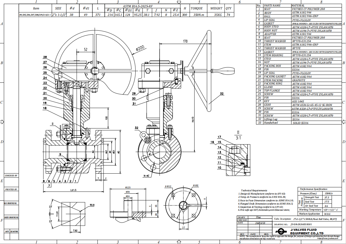
Material Options
The table below is the bill of materials as it is normally quoted, with the upgrades that are actually available rather than the ones that appear in a catalogue header. Anything not visible on the drawing or the certificate is left to the EN 10204 3.1 document instead of being guessed here. The ball is a solid forging rather than a coated carbon core, and that is the one place where a buyer can be sold something cheaper without seeing it. A chrome plated carbon ball looks identical in a photograph and is a different valve after two years in water. Ask for the ball grade on the certificate by name. The seat is where the valve's real temperature limit lives.
PTFE is the standard, RPTFE and PPL extend the ceiling, and a metal seat with flexible graphite goes further but changes the leakage class at the same time. A metal seat does not seal to the same acceptance as a soft seat, so the temperature and the tightness have to be ordered together. Wrought and cast are the same alloy and two different products, and the certificate is where the difference should be visible. A182 covers forged bar, so a body at this size is turned from bar rather than cast, and the question worth asking at the quotation stage is whether the mill certificate names the heat rather than only the grade.
A cast body has no forging direction in the grain; that is one reason a small valve is normally forged, and the reason is cost at this size rather than strength in the abstract. The seat and the packing fail for different reasons and should be chosen separately. A PTFE seat fails by deformation under load and temperature, and the symptom is a valve that will not hold after a warm shutdown. Packing fails by extrusion and by thermal cycling, and the symptom is a drip at the gland that stops when the line cools. That is why a valve can be tight on the seat and still wet at the stem, and why the two materials belong on separate lines of the order rather than on one line called sealing.
| Component | Standard Material | Optional Upgrade | Service Notes |
|---|---|---|---|
| Body and end cap | ASTM A182 F316 forging | A182 F316L for welded fabrication | Product form is fixed by the stamp: F316 is wrought, casting would read CF8M |
| Ball | Solid F316, polished | F316 with hard chrome or ENP | Solid ball, not a coated carbon core; grade confirmed on the certificate |
| Stem | A182 F316 | 17-4PH or nickel based alloy for higher strength | Extended length machined from one bar unless a coupled stem is ordered |
| Seat | PTFE | RPTFE, PPL, or metal seat with flexible graphite | The seat, not the body, sets the upper temperature |
| Packing | PTFE V rings | Flexible graphite with wire reinforcement | Sits in the gland at the body neck, inside the insulation |
| Gasket | PTFE envelope or spiral wound | Flexible graphite filled spiral wound | One joint only, at the end cap |
| Bolting | A193 B8M with A194 8M nuts | B7 with 2H nuts for non corrosive duty | B7 on a stainless body is the corrosion weak point of the joint |
Technical Specifications
The specification below follows the stamping and the drawing. Where the original data sheet gave a value that the standards do not support, the row states the basis instead of repeating the number. The rating line deserves one sentence of explanation. Class 150 in group 3.1 reads 275 psi at 38 C, while the same class in carbon steel reads 285 psi. Stainless is the lower of the two at this class, which is the opposite of what most buyers assume when they pay for an upgrade. The temperature line is deliberately split in two.
Group 3.1 covers a wide body range, but a PTFE seat stops well before the body does, and a metal seat changes the leakage acceptance. One number cannot describe both, so the valve is sold against the seat that was ordered. Class 150 is the line class rather than a statement about this valve. On a three quarter inch branch the piping specification decides the rating long before the pressure does, and the practical effect of going up a class is a heavier flange rather than a stronger body. That is worth saying because buyers sometimes assume a higher class buys temperature too.
It does not: the body would carry more and the seat would still decide how hot the valve can run. The flange is common across the whole class, which is why the class cannot be read from the pipe side. At this size a Class 150 flange is a four bolt pattern, and four bolts is what the spanner sees whether the valve was made for the low end of the class or the top of it. The only place the class is written is the stamping on the body, and that is why the certificate has to be read against the stamping rather than against the order description.
| Item | Value |
|---|---|
| Type | Two piece side entry floating ball valve, soft seated |
| Nominal size | 3/4 x 1/2 inch, DN20 ends by DN15 bore |
| Pressure class | Class 150, stamped 150LB on the body |
| Pressure designation | PN 20, the designation API 6D clause 7.2 writes against Class 150 |
| Shell rating | 275 psi (19.0 bar) at 38 C, ASME B16.34 group 3.1 |
| Body material | ASTM A182 F316 forging |
| Bore | Reduced, one nominal step below the end size |
| End connection | Raised face flanged to ASME B16.5, Class 150 |
| Alternative ends | NPT to B1.20.1, socket weld to B16.11, butt weld to B16.25 |
| Face to face | ASME B16.10 for the size and class ordered |
| Stem extension | 150 to 500 mm as standard, project length on order |
| Packing location | Gland at the body neck, outside the extension |
| Operator | Lever, clamped boss, locking hole available |
| Temperature, body | Group 3.1 range, flanged rating listed to 538 C |
| Temperature, valve | Set by the seat ordered, not by the body |
| Design standard | ASME B16.34, API 608 |
| Test standard | API 598 |
| Fire test | API 607 and ISO 10497 when specified |
| Anti static | Spring loaded contact, ball to body, 10 ohm or less |
Standards and Compliance
API 608 is the right product standard here and it is worth saying so plainly, because the same sentence is wrong on most of the high pressure pages in this catalogue. For flanged ends, API 608 covers DN15 to DN600 at Class 150, 300 and 600; for threaded ends it covers DN8 to DN50 at Class 150 to 800. A forged DN20 valve at Class 150 sits comfortably inside that envelope. The test standard is not the same thing as the acceptance criterion. API 598 fixes the test pressures; for a soft seated valve the acceptance is no visible leakage, which is a stricter statement than the standard's own wording for metal seats.
That is why a soft seated valve and a metal seated valve at the same class cannot share one tightness claim. Fire safe is a design property, not a test result that can be claimed loosely. When the PTFE seat is destroyed, the ball lands on the metal shoulder behind it and the body joint is held by a graphite gasket, which is why that joint cannot be a PTFE flat gasket. Ask for the certificate that covers this size band rather than the logo on the cover.
Anti static is a small part with a large consequence on this valve. A floating ball is not bonded to the stem by a shaft, so the only path from ball to body is the contact that has been designed in, and on a long stem that path is longer and has more joints in it. The requirement is a resistance below the figure the product standard sets, measured after assembly. A valve that fails it is not dangerous in every service, but it is unacceptable in gas and in any line where static has somewhere to accumulate.
| Requirement | Standard | What J-VALVES Supplies |
|---|---|---|
| Pressure boundary design | ASME B16.34 | Wall thickness and material group stated on the drawing |
| Product standard | API 608 | Anti static device, fire safe design, marking to the standard |
| Pressure testing | API 598 | Shell test at 1.5 times rating, seat test at 1.1 times rating |
| Fire qualification | API 607, ISO 10497 | Certificate covering the size and class band ordered |
| Flange drilling | ASME B16.5 | Raised face Class 150, other ends to the standards listed |
| Face to face | ASME B16.10 | Length per the table for the size and class |
| Material certification | EN 10204 3.1 | Heat number on the body and the cap, grade on the certificate |
| Marking | API 608 and ASME B16.34 | Size, class, grade, works number and heat number on the body |
Manufacturing Process
The body starts as a forging, is normalised and solution annealed to the A182 condition, then machined in one setup for the bore and the joint face so the seat pocket and the cap spigot stay concentric. The extended stem is machined from bar in a single length, which is why the guide collar can be positioned for the length ordered rather than at a fixed point. Welding is limited to the seat shoulder overlay where one is specified.
Everything else is machined, so there is no heat affected zone in the pressure boundary and no post weld treatment to argue about on the certificate. The stem, being outside the boundary, is not part of the shell test. Assembly is where the extension earns its cost. The gland is set, the lever boss is clamped at the correct height for the insulation thickness, and the whole assembly is turned through a full quarter turn on the bench to confirm that the guide collar does not bind. A valve that binds on the bench will bind harder on a hot line.
The ball is lapped against its own seat rather than to a nominal size, and that is the step that decides whether the valve holds cold. A ball that is round to a tolerance but not matched to the seat will seal at one temperature and weep at another, because the contact band moves as the polymer creeps. Matching the two parts is a bench operation and it does not appear on any certificate, which is precisely why buying on a data sheet alone is a gamble on the workshop rather than on the specification.

Quality Control and Testing
Every unit is shell tested and seat tested, and the stem is turned under pressure to prove the packing. The step that matters most on a forged body is the one buyers rarely ask for: product form and heat identity on the certificate, matched against the stamping. Portable alloy analysers read the family, not the carbon content, so a gun reading cannot separate 316 from 316L and cannot confirm that a body said to be forged was not cast. Both answers come from the mill certificate. That is not a reason to skip the gun; it is a reason to read the paper as well. The extension adds one check that a standard valve does not need.
Because the lever works at the top of a bar rather than at the gland, the assembly is turned with the lever fitted and the deflection at the guide collar is observed. A stem that whips under load will eventually wear the packing on one side. Bench assembly on an extended stem valve has one alignment step that is easy to skip and expensive to discover later. The guide collar and the gland bore have to be concentric, and the check is made with the extension fitted and the lever turned through the full quarter, before the insulation goes on. A column that binds slightly on the bench will bind hard once the cladding is on and somebody is working the lever through a hatch, and by then it is a maintenance item rather than an isolation point.
The two documents a buyer keeps are the certificate and the test sheet, and on a small valve the second is the one that gets skipped, because the test takes minutes while the record takes longer to write. That is the wrong way round. The certificate says what the metal is; the test sheet says the valve held, at what pressure and for how long, and with which seat arrangement. Without the second, a leak on site becomes an argument about whether the valve was ever tested at all, and the answer will be a photograph of a gauge nobody can date. Ask for the record with the works number on it, and ask for both seats rather than a single line saying the valve passed.
| Step | What Is Checked | Standard or Acceptance |
|---|---|---|
| 1 Incoming material | Heat number, grade, product form | A182 F316 forging, certificate matches the stamping |
| 2 Dimensional | Bore, end sizes, face to face, joint face | Drawing and ASME B16.10 for the class |
| 3 Machining | Seat pocket concentricity, gland bore, stem straightness | In house tolerance on the signed drawing |
| 4 Cleaning | Free iron and contamination on stainless surfaces | A380 passivation, ferroxyl test when the project asks |
| 5 Shell test | Body and joint under pressure | API 598, 1.5 times rating, no leakage |
| 6 Seat test | Both seats, both directions | API 598, 1.1 times rating, no visible leakage |
| 7 Packing and stem | Turning under pressure, gland adjustment | No leakage at the gland through the full quarter turn |
| 8 Marking and records | Stamping, heat traceability, test record | Certificate and test sheet issued with the valve |

Applications and Industry Service
The obvious duty is a small branch off a traced or insulated header, where the valve body has to sit inside the lagging and the handle has to come out of it. Sample coolers, gauge roots, dosing injection points and analyser take-offs are the same problem in different clothes: a small valve in a place where nobody wants to cut the insulation to reach a handle. The second duty is anywhere the operator has to stand at a safe distance from the line itself, whether because of temperature, height or access. The extension is a mechanical answer to an ergonomic question, and it is cheaper than a platform, a chain wheel or a remote actuator on a valve this size. What it is not for is worth one paragraph.
A reduced bore valve cannot pass a pig, so it does not belong on any line that may later be cleaned by one. A floating ball valve cannot do double block and bleed, because only the downstream seat is loaded at any time. And a soft seated valve is an isolation device, not a control device; throttling on a PTFE seat destroys it quietly. Small bore isolation on a hot line fails in three recognisable ways and only one of them is the valve's fault. The seat scores when the valve is used to throttle, the packing weeps after a few thermal cycles, and the body joint leaks when the studs were tightened by feel rather than to a figure.
The first is a selection error, the second is normal wear and the third is an installation error, and separating them is what turns a failure report into something useful rather than a complaint about the supplier. Stainless is the right body for a good deal of what this valve does, and it is not the right body for everything. In a chloride bearing duty, 316 fails by pitting and by crevice attack rather than by general corrosion, and the crevice it finds first is usually under a gasket or a bolt head where nobody is looking. A page that offers stainless as the answer to corrosion has answered half the question; the other half is what the medium contains and whether the valve will sit wet.

Installation, Operation and Maintenance
Install with the stem vertical or horizontal, never inverted, and leave the guide collar free of lagging so the stem does not rub on the cladding. The extension is a lever arm, so anything that touches it becomes a side load on the packing. Clamp the cladding around the stem with a collar rather than packing mineral wool against a moving bar. The honest cost of the extension belongs here. The handle comes out of the insulation; the packing does not. Adjusting the gland means removing a section of cladding and reaching past the stem to four socket head screws at the body neck, which is a slower job than it would be on the same valve without an extension.
Plan the access before the insulation goes on, not after the first weep. Operation is a quarter turn with a hard stop at each end. Do not use the lever as a step or a lever point for pipe alignment, and do not leave the valve part open as a flow control. For maintenance, isolate, vent and drain the cavity before removing the cap, and renew the body joint gasket rather than reusing it; a compressed spiral wound gasket does not seat twice.
What to keep on the shelf for a valve this size is a short list: one body joint gasket, one seat set and one packing set per valve in critical service. The gasket is single use by design and cannot be reused once the joint has been opened, whatever the workshop practice is, and a seat scored by throttling cannot be restored by tightening anything. Keeping the three parts costs very little against the downtime of waiting for them, and it turns a seat change into an afternoon rather than a purchase order.
How to Specify and Order
Six fields decide the price and the delivery of this valve, and every one of them has a default that will be assumed if it is left out. Size and bore, meaning 3/4 x 1/2 inch rather than just 3/4 inch. Pressure class and the flange standard, since a PN marked valve and a Class marked valve are drilled to different tables. End connection, because flanged, threaded, socket weld and butt weld are four different bodies. Seat material, which sets both the temperature and the leakage acceptance. Extension length and its datum, measured from the body centre line or from the flange face. And the operator interface, meaning lever, bare stem with a mounting pad, or actuator.
Alongside those, ask for the documents by name: the EN 10204 3.1 certificate with heat numbers matching the stamping, the API 598 test record, the fire certificate covering this size and class, and the signed general arrangement drawing with the extension length and its datum marked. The one duty where an extended stem is the wrong answer is high temperature at the packing. Lifting the operator clear of the lagging does not move the gland, so a line hot enough to destroy PTFE will still destroy it at the body neck. That case needs a valve with an extended bonnet, where the packing itself is carried out of the hot zone, and the two are not interchangeable however similar they look in a photograph.
Asking which of the two is being quoted is the fastest way to find out whether an offer is right. Commissioning is the last chance to catch a stem problem, and it takes a quarter turn. With the line at pressure and the insulation still off, work the lever through its full travel and watch the column for lateral movement; a guide collar that is out of line shows up as a slight bind at one end of the travel and as nothing at all in the middle. Once the cladding is on, that same bind is a lever that has to be forced, and a forced lever on a small valve is how stems get bent.
FAQ
Q: What does the F316 stamp on the body tell me?
A: It names the alloy and the product form at the same time. Wrought 316 is ASTM A182 F316; cast 316 is A351 CF8M. A body stamped F316 is therefore a forging, and that is a claim you can check without opening the valve.
Q: Is 3/4 x 1/2 inch a reducing flange valve?
A: No. Both ends are DN20 and the bore through the ball is DN15. The flanges, the face to face length and the lever are all sized for the end size, so gaskets and spool pieces are ordered for DN20.
Q: Does the extension move the packing out of the insulation?
A: No. The gland stays at the body neck and the extension is an external stem with a guide collar. Moving the packing is an extended bonnet, which is a different valve with a different drawing and a different shell test.
Q: Can this valve do double block and bleed?
A: No. A floating ball is pushed against the downstream seat by the pressure, so the upstream seat is unloaded and only one seat seals at a time. There is also no cavity drain on this body to bleed through.
Q: Is PN 20 the same as Class 150?
A: API 6D clause 7.2 writes PN 20 against Class 150, so the designation is correct. The flange is still drilled to ASME B16.5, because EN 1092-1 has no PN 20 step, and a European line needs a different body.
Q: Can it be used on steam?
A: Only with the right seat. A PTFE seat is a long way below the body rating, so steam duty needs RPTFE, PPL or a metal seat, and the temperature has to be in the enquiry. The body rating is not the answer to a steam question.


Hot Products


News
Ball Valve Condition Monitoring: Which Signals Actually Predict A Failure
Torque signatures, acoustic emission, differential pressure and digital twin residuals: which measurements find a failing ball valve early.
Read More
Ball Valves in SWRO Desalination: The High Pressure Section Where Ordinary Seawater Valves Fail
Why SWRO high pressure valves fail early: recovery arithmetic, crevice temperature, ERD ripple, scale, letdown cavitation and surge.
Read More
Air Test And Water Test For Ball Valves: What Each Medium Can Prove
A ball valve can pass a hydrostatic seat test and still leak gas. Why air and water prove different things, and how to read a bubble, decay or helium test.
Read More
Ball Valve Flange Bolting: Preload, Relaxation And The Fasteners That Decide Leakage
A weeping flange is rarely the gasket. Preload, torque scatter, hardness limits and thermal relaxation decide whether the joint holds at 100 bar and 400 C.
Read More