


CHINA J-VALVES Offers Various High-quality I ndustrial Ball Valves
J-VALVES, a distinguished professional ball valve manufacturer rooted in China, takes pride in its extensive product portfolio. Our offerings span a wide range, including trunnion-mounted ball valves, floating ball valves, high-temperature ball valves, high-pressure ball valves, metal-sealed ball valves, ultra-low temperature ball valves, DBB ball valves, Three-way And Four-way Ball Valve, and fully welded ball valves. Each product is a testament to our commitment to precision engineering and reliable performance. Meticulously crafted, they are designed to not only meet but exceed the most stringent industrial demands, ensuring stable operation even under extreme conditions. This enables us to provide our clients with high-value services and makes our valves widely sought-after in industries.
Product Category
Contact Us

-
J-VALVES-Q347F
-
J-VALVES
A cryogenic ball valve for LNG service is a quarter-turn isolation valve with an austenitic stainless pressure boundary, an extended bonnet and PCTFE seats, designed to isolate liquefied natural gas at about -162°C on unloading, storage, boil-off gas and send-out lines. J-VALVES manufactures this family in Wenzhou, Zhejiang, from 1/2 inch to 56 inch and ASME Class 150 to 2500, built to BS 6364 design rules and tested cryogenically to ISO 28921-1 when the purchase order calls for it.
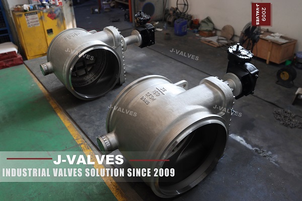
A terminal is not one temperature. Unloading arms sit near tank pressure, send-out pumps push towards 100 bar, boil-off gas returns as dry vapour, and the flare header stays cold and idle for months. This page maps those service points, the material choices behind them, and the liquid-versus-vapour differences that decide how the valve is built.
Service Points Across the LNG Chain
An LNG terminal ball valve is chosen by service point rather than by plant. Every terminal repeats the same functions: receive at the jetty, store, boil off, compress, send out, reload. Each fixes a different mix of size, class and operating pattern, so a specification written function by function is easier to review than one plant-wide standard.
Service point | Valve duty | Typical size | Typical class | What sets the selection |
|---|---|---|---|---|
Ship unloading arms and vapour return | ESD isolation at the jetty head | 16 to 24 inch liquid, 8 to 16 inch vapour | Class 150 to 300 | Arm design pressure, ESD timing |
Storage tank inlet and outlet | Fill line and tank isolation | 6 to 24 inch | Class 150 to 300 | Tank nozzle size, low line pressure |
In-tank pump discharge | Isolating an in-tank pump | 6 to 16 inch | Class 300 to 600 | Pump shut-off head |
BOG compressor suction | Isolating the cold suction header | 8 to 24 inch | Class 150 to 300 | Low pressure, large flow |
BOG compressor discharge | Isolation before recondenser or fuel gas | 4 to 16 inch | Class 300 to 600 | Final stage discharge pressure |
High pressure send-out | Isolation before the vaporisers | 6 to 16 inch | Class 600 to 1500 | 70 to 100 bar pump discharge |
Reloading | Loading line to a ship at a second berth | 12 to 24 inch | Class 150 to 300 | Same basis as unloading |
Flare and vent | Cold relief and blowdown isolation | 2 to 12 inch | Class 150 to 300 | Flare header design pressure |
Those ranges are typical, not fixed. Line size follows the hydraulic calculation and class follows the line design pressure from the P&ID, so a 20 inch unloading line and a 20 inch send-out header can sit three classes apart. Temperature varies least: every row except the warm end of the BOG compressor sees metal at -150°C or colder.
Two rows need separate attention. The unloading arm valve is an ESD valve, so the specification adds a closing time, proof of closure and partial stroke testing, which changes the actuator rather than the body. The flare valve may stand closed for a year before it opens against a cold relief load, a different duty from an ESD valve.
Austenitic Stainless as the Default Pressure Boundary
The pressure boundary of a cryogenic ball valve for LNG is austenitic stainless at every wetted part: body, bonnet, ball, stem, seat rings and the extension tube. Below about -50°C, carbon and low-alloy steels enter the ductile-to-brittle transition, and Charpy energy falls from hundreds of joules to single digits. Impact-tested low-temperature carbon steels stop at about -46°C, well short of liquefied methane.
A brittle body does not leak first. It fractures. Stress concentrates at the body joint, seat pocket, stem bore and flange fillets, which is where a cleavage crack starts. At -162°C the same body holds a liquid with an expansion ratio near 600 to 1, so a sudden failure releases a large volume of flammable vapour in seconds.
Cast grades are CF8M and CF3M to A351, roughly 18 percent chromium, 10 percent nickel and 2.5 percent molybdenum, with CF3M at about 0.03 percent carbon maximum for weldability. Forgings are F304, F316 and F316L for small sizes, weld-end bodies and stems. CF8M carries a minimum yield of 205 MPa and a minimum tensile of 485 MPa.
Austenitic stainless has a face-centred cubic lattice with no cleavage mode in this range, so toughness is inherent rather than recovered by alloying. It is still impact tested: the requirement commonly quoted from ASME B16.34 for cryogenic service is 0.38 mm minimum lateral expansion on three specimens, and J-VALVES records the Charpy results against heat number and valve serial number.
Two secondary properties matter. Expansion is about 16 x 10^-6 per K, so a 100 mm dimension loses 0.29 mm between 20°C and -162°C, and every bolted joint and seat interference has to absorb that. Thermal conductivity is around 16 W/m·K, a third of carbon steel, which slows heat leak down the bonnet but does not remove the need for the extended bonnet.
9% Nickel Steel: Where It Belongs
Nine percent nickel steel to A353 and A553 is the other cryogenic material a buyer meets on an LNG terminal, and buyers sometimes ask why the valve body is not made from it. Its economics and fabrication route fit tanks and large pipe, not castings in this size range.
Nickel lowers the ductile-to-brittle transition of ferritic steel without the cost of an all-austenitic composition. In the quenched and tempered condition A553 Type I reaches a minimum yield around 585 MPa, nearly three times CF8M, with toughness held to -196°C and thermal expansion roughly half that of stainless. High strength and low contraction are what a tank designer wants: thinner plate, less weld metal, smaller thermal stress at the shell-to-bottom corner.
That is why 9% nickel appears in the inner tank shell, the tank bottom, the annular plate, the tank nozzles and some large-bore cold pipe spools. It does not appear in valve bodies of this size. Cast 9% nickel is not a routine foundry product, and its toughness depends on a precise normalise and temper or quench and temper cycle that is hard to guarantee through a heavy cast section. Seat pockets and flange necks need weld overlay and close machining that the alloy resists. And the ball, stem and seat rings would still be stainless, so a 9% nickel body would contract at half the rate of its own trim, changing seat interference by an amount no standard design covers.
For an LNG ball valve at -162°C in these sizes, austenitic stainless is the practical answer.
LNG Liquid Against BOG Vapour: Real Differences
A BOG ball valve and a liquid LNG valve can look identical from the outside and behave differently in service. Both are cold, both are flammable, both sit inside the same fire envelope. The differences below decide seat design, test medium, actuation and leak detection.
Parameter | LNG liquid service | BOG vapour service |
|---|---|---|
Metal temperature at the valve | -162°C to -150°C | -160°C at suction, rising after compression |
Density | about 430 to 470 kg/m3 | about 1.5 to 2 kg/m3 |
Lubricity at the sealing line | liquid wets the seat, fills micro-clearances | dry gas, no film, higher friction |
Dominant leak path | seat, body joint, gland | seat, gland, bonnet micro-paths |
Leak signature | visible white plume, boiling pool, cold spot | invisible flammable cloud |
Cavity behaviour | trapped liquid expands on warming | compressible, no liquid lock |
Erosion driver | droplets and carried solids | droplets at high velocity, compressor pulsation |
Start with sealing. Liquid fills the asperities on a PCTFE face and helps the seat hold. Dry gas does not. It passes any open path and desorbs the thin film that keeps a polymer seat cool, so friction rises, the seat moves in stick-slip, and the sealing line wears faster. The countermeasure is mechanical: spring-energised seats that hold contact stress constant, a finer ball finish, and no reliance on the medium for lubrication.
Do not add grease to cure a dry-gas squeak. Grease solidifies at -160°C, collects at the sealing line, and the next stroke scores the seat.
Erosion differs too. BOG leaving a compressor carries pulsation and, after a long shutdown, mill scale from the warm header; at 20 m/s and above those particles arrive at the seat like grit, and a two-phase slug from a knock-out drum does the same damage faster.
The leak consequence is the difference that changes plant design. A liquid leak announces itself: a white plume, a growing pool, ice on the pipe, a cold spot a thermal camera sees at 30 metres. Oxygen deficiency in a pit is the immediate hazard, and spilled LNG can chill structural steel below its transition range. A gas leak gives none of those warnings. Methane is lighter than air, but in a congested rack it disperses slowly and the cloud is invisible until a detector finds it. That is why BOG valves are normally tested on gas.
Two-Phase Flow and the Cold Letdown
An LNG send out ball valve spends most of its life fully open, and that is how it should be sized. The problems start when it is used to throttle. Liquid methane at 70 to 100 bar dropping to a few bar across a partly open ball flashes as it passes the seat, and the volume grows by a factor of several hundred. The result is a high-velocity mixture of gas and droplets leaving the seat corner at sonic speed, impinging on the downstream body wall, and turning the pipe into a cold spot within minutes.
The symptoms are noise, vibration, a frost patch downstream, and a slow loss of seat tightness over the following months. Droplet erosion removes the sharp edge of the sealing band, and once the band widens the contact stress falls. Solids make it worse; commissioning debris and mill scale travel with the liquid and strike the same corner.
Three rules follow. Size the valve for isolation at full open, not for throttling. Where a permanent letdown is required, put a control valve with a multi-stage trim in the line and keep the ball valve as the isolation device. Where a ball valve must throttle during commissioning or an emergency, use a metal seated trim, limit the travel, monitor the downstream wall temperature, and return the valve to fully open as soon as the operation allows.
The same physics explains why cool-down is slow. Liquid entering a warm line flashes until the metal cools, and mixture velocity in that period is far above steady state. A valve fully open during cool-down presents the least obstruction and the lowest local velocity.
The Standards That Frame an LNG Valve Order
The standards landscape around an LNG terminal splits between documents that govern the valve and documents that govern the installation. Confusing the two produces unanswerable vendor questions, because a valve maker designs and tests to the first group and can only supply evidence for the second.
Standard | What it covers | Who applies it |
|---|---|---|
BS 6364 | Cryogenic valve design and testing to -196°C, bonnet length, materials | Valve designer and manufacturer |
ISO 28921-1 | Cryogenic isolating valves, design, manufacture and testing | Valve manufacturer and test house |
API 6D and API 608 | Valve design, pressure testing, anti-static provisions | Valve manufacturer |
ASME B16.34 | Pressure and temperature ratings, wall thickness, impact requirements | Valve designer |
EN 1473 | Design of onshore LNG installations and equipment | Terminal designer and EPC |
NFPA 59A | Production, storage and handling of LNG, fire safety and siting | Terminal designer, authority having jurisdiction |
ISO 16904 | Design and testing of marine transfer systems, arms and hoses | Jetty and marine designer |
BS 6364 is the document a cryogenic valve is usually measured against. It expects materials to remain ductile at the service temperature, the bonnet to keep the gland out of the cold, and the finished valve to be proved at low temperature rather than only at ambient. ISO 28921-1 covers the same ground from the test side and defines how a cryogenic test is run.
EN 1473 and NFPA 59A sit above the valve. They define terminal layout, where ESD valves are required, what fire protection is needed and how a release is contained. A supplier can state that a product suits the service these documents describe, but conformity of the installation belongs to the terminal designer.
ISO 16904 applies at the water's edge. Marine transfer adds requirements land-based valve standards do not: powered emergency release, a disconnection sequence, and defined behaviour for the valves at both ends when the coupling separates. A jetty ESD valve is therefore specified from ISO 16904 practice and the arm supplier's interface document, with BS 6364 material and test requirements underneath.
Fire-Safe and Anti-Static Requirements
Two requirements are routinely confused on an LNG terminal. Fire-safe construction keeps the valve sealing after a fire has destroyed its polymer components. Anti-static construction stops the valve becoming the ignition source.
Fire testing to API 607 burns a valve at a defined flame temperature while it is pressurised, then measures leakage during the burn and after cool-down. The test assumes the soft seat is gone, so what must survive is the secondary path: a metal seat face behind the PCTFE ring, flexible graphite packing, a graphite or spiral wound body gasket, a blowout-proof stem, and a body joint that does not open when its bolting reaches several hundred degrees. External leakage is usually the harder criterion, which is why a graphite gland is specified even on a metal seated valve.
The fire case is credible. A flange leak, a pump seal failure or an arm disconnection produces a pool that burns under the pipe rack, and the ESD valves there are expected to keep isolating while the fire is fought. The wording should be explicit: fire tested to API 607, report traceable to the serial number, graphite packing and gaskets in the build.
Anti-static is a separate provision. A polymer seat and polymer packing can isolate the ball electrically from the body, and flowing dry gas generates charge on an ungrounded surface. Methane has a minimum ignition energy near 0.3 mJ, a very small spark. The answer is a spring-loaded plunger between stem and body, or a conductive path through the seat carrier, so ball, stem and body stay bonded. Resistance between ball and body is measured at assembly, typically required below 10 ohm, and recorded.
Static matters more in BOG service, because dry gas generates far more charge than a liquid that wets the surfaces, and most of all during blowdown when high-velocity gas passes a seat that has just opened. A valve that is fire-safe but not bonded can still ignite the release it was installed to contain.
Nitrogen Purging, Desiccant and Site Storage
Preservation starts before the cryogenic ball valve for LNG leaves the test bay. A hydrostatic test leaves water in the body cavity, the seat pockets and the bonnet extension, and water at -162°C becomes ice that can lock the ball and damage the seat. Everything after the shell and seat test is about removing moisture and keeping it out.
Step | What is done | Typical value or check |
|---|---|---|
Drain and dry | Air blow through bore and cavity, then vacuum or dry nitrogen sweep | No free water, no visible moisture |
Nitrogen purge | Dry nitrogen through bore, cavity and bonnet until the outlet dew point stabilises | -40°C dew point, -60°C where the specification is stricter |
Blanket charge | Nitrogen left in the body at positive pressure | 0.2 to 0.5 bar gauge |
Desiccant | Bags in bore and end-cap space, with indicator | Indicator still blue at dispatch |
Flange protection | Caps with a gasket, no adhesive on the flange face | Caps remain until installation |
The dew point target is worth arguing about early. Minus 40°C is the common terminal figure and is adequate for a valve purged again on site. Some specifications ask for -60°C, reachable with a longer purge and a dry nitrogen supply of adequate quality, but it costs shop time and is lost the moment a cap comes off in a humid climate. J-VALVES states the achieved dew point on the packing list.
Site storage rules are simple and often broken. Keep the valve crated, indoors or under cover, on a pallet clear of the ground, with the caps on until installation. Do not lift by the gearbox or the extended bonnet; the bonnet is a lever and the body joint is not designed for a bending moment. Do not store near a welding station, because spatter on a lapped ball cannot be repaired on site.
Long storage needs a schedule. Check the nitrogen pressure monthly and top it up. Replace the desiccant if the indicator has changed. After six months, or any period with the caps off, repeat the purge and record the new dew point. A valve that stood open in a humid warehouse for a year has an unknown internal condition, and the first cool-down is not the moment to discover it.
Commissioning: Drying, Cool-Down and the First Re-Torque
Commissioning is a sequence of drying, inerting and controlled cooling. Each step has an acceptance value that belongs in the procedure, not in the contractor's judgement.
Dry the line. Blow through with oil-free dry air or nitrogen and measure dew point at the lowest drain until it holds at -40°C or the project target. Water behind a closed seat will not show at the header, so cycle each valve once.
Inert the section. Purge with nitrogen until oxygen falls below the project limit, typically 1 percent by volume, and hold positive pressure until LNG is admitted. Methane in air is flammable from about 5 to 15 percent.
Stroke the valve. Record open and close torque against the shop figure for that serial number. A rise beyond about 30 percent points to a seat problem, packing over-tightened for transport, or a bent extension.
Cool down slowly. The usual limit is 20 to 40 K per hour, set by the piping stress analysis rather than the valve. Frost should stop below the gland; frost at the gland means the bonnet is too short for the insulation, or the insulation is wet.
Re-torque after the first thermal cycle. Bring the valve to ambient, then re-torque body and bonnet bolting in a cross pattern with a calibrated wrench. Differential contraction and gasket relaxation reduce preload, so a joint correct in the shop is usually below specification afterwards. Never re-torque a cold joint.
Leak check and record. Use a portable methane detector at the gland, the body joint and the flange faces after cool-down, then again after the first warm-up. Log torque, dew point, oxygen reading and leak result against the serial number.
Documentation comes with the valve: an EN 10204 3.1 material certificate, shell and seat test records to API 598 tied to the serial number, dimensional reports to ASME B16.10, impact results for the body heats, and the shop torque measurement. Delivery is typically 4 to 8 weeks depending on configuration and material availability.


Cryogenic Ball Valve for LNG FAQ
Which parts of an LNG terminal use cryogenic ball valves?
Every point where a line has to be isolated while cold. That covers the ship unloading arms and vapour return, the storage tank fill and outlet nozzles, the in-tank pump discharge, the BOG compressor suction and discharge, the high pressure send-out line ahead of the vaporisers, the reloading line, and the flare and vent headers. Sizes run from 2 inch on a vent branch to 24 inch on an unloading arm, and classes from 150 to 1500 depending on line design pressure.
What temperature must an LNG ball valve be rated for?
Liquefied natural gas sits at about -162°C at atmospheric pressure, so the valve must be designed for that metal temperature with margin. Most specifications require the design to cover -196°C, the boiling point of liquid nitrogen, because that is the test medium and the lower bound of BS 6364. A valve offered for -100°C is not an LNG valve. Confirm the low-temperature test temperature on the datasheet, not only the design temperature.
Which standards apply to LNG terminal valves?
Two groups. The valve itself is designed to BS 6364 and tested to ISO 28921-1, with API 6D or API 608 and ASME B16.34 underneath for pressure rating and anti-static provisions. The installation is governed by EN 1473 in Europe and NFPA 59A in North America, and jetty equipment by ISO 16904. A valve manufacturer works to the first group and supplies evidence for the second, which remains the terminal designer's responsibility.
What is different about BOG service compared with LNG liquid service?
The medium is dry. A liquid wets the seat and fills micro-clearances, while gas does not, so friction rises, stick-slip appears and the sealing line wears faster. Gas also generates far more static charge, which makes the anti-static bond more critical. Leak detection differs as well: a liquid leak shows a white plume and a cold spot, while a gas leak is invisible. BOG valves are normally tested on gas rather than water.
Do LNG ball valves need fire-safe certification?
Terminal specifications almost always require fire-safe construction, because a pool fire under a pipe rack is a credible event. The practical requirement is a valve fire tested to API 607, with graphite stem packing, graphite or spiral wound body gaskets and a metal secondary seat, and a test report traceable to the serial number. Ask for that report rather than for the word fire-safe on a datasheet, since the external leakage result is what usually decides the outcome.
How are LNG valves protected during shipment and storage?
After the hydrostatic test the valve is drained, dried and purged with dry nitrogen to a dew point of -40°C or lower, left with a small nitrogen blanket, and fitted with desiccant and flange caps. On site it stays crated, indoors, off the ground, with caps on until installation. Check the nitrogen pressure monthly, replace the desiccant if the indicator changes, and repeat the purge after six months or any period with the caps removed.
Hot Products


News
Ball Valve Condition Monitoring: Which Signals Actually Predict A Failure
Torque signatures, acoustic emission, differential pressure and digital twin residuals: which measurements find a failing ball valve early.
Read More
Ball Valves in SWRO Desalination: The High Pressure Section Where Ordinary Seawater Valves Fail
Why SWRO high pressure valves fail early: recovery arithmetic, crevice temperature, ERD ripple, scale, letdown cavitation and surge.
Read More
Air Test And Water Test For Ball Valves: What Each Medium Can Prove
A ball valve can pass a hydrostatic seat test and still leak gas. Why air and water prove different things, and how to read a bubble, decay or helium test.
Read More
Ball Valve Flange Bolting: Preload, Relaxation And The Fasteners That Decide Leakage
A weeping flange is rarely the gasket. Preload, torque scatter, hardness limits and thermal relaxation decide whether the joint holds at 100 bar and 400 C.
Read More